May 28, 2018
security systems resource accounting lighting engineering motor control medicine consumer electronics Littelfuse article discrete semiconductors
Powerful interference that occurs in alternating voltage networks can damage electronic devices. To protect electronics , varistors, TVS diodes, gas arresters and protective thyristors are most often used. The SIDACtor protection thyristors of the Pxxx0FNL and series with peak currents of 3 and 5 kA from Littelfuse are used when high precision of the clamping voltage is required. They combine high stability and a fairly large peak current.
Protection against interference arising in alternating voltage networks is one of the most important tasks facing developers of electronic devices. If this problem is not solved at the development stage, then the lifespan of an unprotected electronic device may be very short.
There are several traditional overvoltage protection elements: metal oxide varistors (MOV, Metal Oxide Varistor), TVS diodes (Transient Voltage Suppressor), gas arresters (GDTs, Gas Discharge Tube) and protective thyristors [1]. Each of them has its own advantages and application features. Therefore, when building a protection system, developers often use a combination of several elements. For example, a thyristor and a varistor can be connected in series.
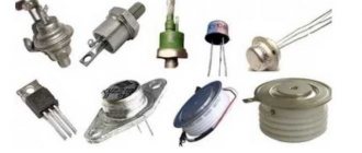
Protective thyristors are distinguished by record stability of characteristics, high switching speed and the ability to repeatedly withstand powerful overvoltage pulses. Unfortunately, their main disadvantage is their low peak current. However, manufacturers are working to solve this problem. For example, quite recently the Littelfuse expanded the SIDACtor line of protective thyristors with two new families - Pxxx0FNL and Pxxx0ME with peak currents of 3 and 5 kA (Figure 1).
Rice. 1. Protective thyristors Pxxx0FNL and Pxxx0ME
Structure and characteristics of SIDACtor protective thyristors
SIDACtor protective thyristors have only two outputs, that is, by definition they are diode thyristors [2]. Their simplified structure includes four layers with different types of conductivity: emitter (upper N-layer), upper base (upper P-layer), middle N-layer, lower base (lower P-layer) (Figure 2). The electrode connected to the emitter is often called the cathode, and the electrode connected to the bottom base is called the anode.
Rice. 2. Simplified structure of SIDACtor protective thyristors
A diode thyristor can be considered as two back-to-back diodes. At low voltages, such a structure does not conduct current in any direction. As the voltage increases, a slight increase in the leakage current is observed. An increase in voltage leads to an increase in the field strength applied to pn junctions. At a certain voltage value, an avalanche breakdown occurs. In this case, the resistance of the thyristor abruptly decreases to a very small value. The conducting state is maintained until the current in the thyristor decreases to a level at which the avalanche breakdown stops. In real circuits, the thyristor turns off when the polarity of the applied voltage changes.
An abrupt change in resistance leads to a break in the current-voltage characteristic of the thyristor (Figure 3). Using current-voltage characteristics, the most important parameters of these components can be characterized.
Rice. 3. Current-voltage characteristic of SIDACtor protective thyristors
VDRM - operating voltage: repeating reverse voltage in the closed state, at which the thyristor does not open.
IDRM – maximum value of leakage current at voltage VDRM.
VS – switching voltage: the maximum voltage at which the thyristor turns on when exposed to a pulse of 100 V/µs. This parameter characterizes the level of voltage limitation.
IS – switching current: the maximum current required to turn on the thyristor.
IH – holding current: the minimum current required to hold the thyristor in the open state.
VT is the maximum voltage drop across the thyristor in the open state.
IT – maximum permissible direct current of the thyristor in the open state.
ITSM is the maximum permissible thyristor current in the open state when exposed to sinusoidal voltage.
IPP – peak current: the maximum permissible pulse current of the thyristor in the open state.
di/dt – maximum permissible rate of current rise.
Coff – own container in a closed state. Typically measured at a voltage of 2 V and a frequency of 1 MHz.
SIDACtor thyristors are semiconductor power components and are able to withstand multiple switching without significant degradation in performance (minimal degradation). However, if the permissible rate of rise of current di/dt is exceeded, the thyristor may fail. At the same time, the value of the maximum current for SIDACtor turns out to be quite modest.
Comparison of characteristics of protective voltage limiters
To protect against powerful interference in AC voltage networks, developers most often use the following protective elements:
- SIDACtor® thyristors;
- metal oxide varistors (MOV, Metal Oxide Varistor),
- TVS diodes (Transient Voltage Suppressor),
- gas dischargers (GDTs, Gas Discharge Tube).
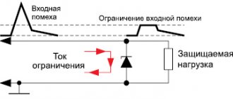
All of the listed elements are connected in parallel to the load and have high resistance in the absence of overvoltages. When powerful interference occurs, the protective component is activated. In this case, thyristors and gas dischargers form a short circuit when triggered, and varistors and TVS diodes limit the interference voltage. Let us consider the advantages and features of the use of all the presented protective components (Table 1) [2].
Table 1. Advantages and features of the use of surge protection elements
| Parameter | Gas arresters | SIDACtor® protection thyristors | Varistors | TVS |
| Mechanism of operation | Breakdown (short circuit) | Breakdown (short circuit) | Limitation | Limitation |
| Peak current level | High | Average | High | Average |
| Response time | More than 1 µs | Less than 1 ns | Range ns | Range ns |
| Peak current, kA | 20 | 5 | 70 | 15 |
| Minimum switching voltage, V | 75 | 8 | 6 | 6 |
| Turn-on voltage accuracy | Low | High | Low | High |
| Surge Control Efficiency | Average | High | Low | High |
| Typical capacitance, pF | ~1 | ~30 | ~1400 | ~100 |
| Voltage in limit mode | ~30 V | ~3 V | Vc | Vc |
| Survival rate | Good | Great | Limited | Good |
| Dimensions/peak current ratio | Low | Average | High | Average |
Thyristors SIDACtor®
When interference occurs with a voltage exceeding Vs, the thyristor opens. In this case, a state close to a short circuit is formed: the voltage on the thyristor abruptly drops to a very small value (units V), and the current increases. This way the load is protected from overvoltages.
SIDACtor thyristors cannot be damaged by voltage. In addition, they are characterized by minimal turn-on time and extremely high stability of the response voltage, which is practically independent of the rate of rise of the dv/dt interference (Figure 4). This makes thyristors an almost ideal choice if high accuracy of clamping voltage is required.
Rice. 4. Stability of switching voltage for various protective components
Important advantages of thyristors are also excellent long-term stability and low intrinsic capacitance.
Features of the use of thyristors include the need to use current protection, for example, fuses. Otherwise, if the permissible values are exceeded, the thyristor will fail.
Gas discharge tubes (GDTs, Gas Discharge Tube)
The operating principle of a gas spark gap is based on the use of gas breakdown [3]. The discharger is a hermetically sealed ceramic flask with an inert gas. The inside of the electrodes has a special shape, which is designed to generate an electric field. In some cases, the arresters are equipped with an additional thermal fuse (Failsafe Clip). When a gas discharge occurs, as in the case of thyristors, a state close to a short circuit is formed.
The main advantages of gas arresters are high peak currents of up to 20 kA and record low intrinsic capacitance (units pF). Arresters are most often used as the first line of protection against surges and are ideal for high frequency circuits.
The disadvantages of arresters include a long turn-on delay, high and unstable clamping voltage, and degradation.
Metal Oxide Varistors MOV
Varistors are the most common type of protective components for AC voltage networks [4].
Most often, zinc oxide ZnO is used for the production of varistors. At low voltages, ZnO is effectively a dielectric with leakage currents in the microampere range. When the voltage increases above a certain limit (breakdown voltage), local heating of the oxide occurs, which leads to reversible breakdown. During breakdown, the resistance sharply decreases and the current increases. An increase in current leads to an increase in the released power and heating of the varistor structure. A significant increase in power dissipation can lead to irreversible thermal runaway. In this case, the structure of the varistor is destroyed.
Varistors are characterized by record high peak currents of up to 70 kA and are able to effectively absorb powerful interference. However, their disadvantages are degradation of parameters, high capacitance and strong dependence of the limiting voltage on current.
TVS diodes
The operating principle of the protective TVS diode is based on the use of reversible breakdown [5]. If a voltage with an amplitude greater than a certain value (breakdown voltage) is applied to the TVS, a breakdown will begin with an avalanche-like increase in carriers. The current passing through the diode increases almost unlimitedly, and the voltage changes only slightly. As a result, the input voltage is limited.
TVS diodes effectively cope with fast noise, are highly stable and have a long service life. However, TVS diodes are not ideal protective limiters. During breakdown, as the current increases, the voltage across the diode increases, although not so quickly. This leads to the fact that the limiting level depends on the power of the interference: the more powerful the interference, the higher the limiting voltage.
Thus, all of the listed elements have their pros and cons. For this reason, developers often use different components to be included together. For example, connecting a varistor and a thyristor in series allows you to obtain a low clamping voltage. We should not forget that manufacturers continue to improve the characteristics of their products.
Analog Devices Active Voltage Limiters
Most active limiters manufactured by Analog Devices are designed to use external FETs. This expands the possibilities of their application, since by selecting an external transistor it is possible to provide the required level of maximum input voltage. For example, the LT4356 (Figure 5) has an operating voltage range of 4...80 V with the possibility of a short-term increase to 100 V. Such characteristics are quite sufficient for, for example, most automotive on-board power supply systems with voltages of 12 or 24 V. However, this chip can also be used in applications where higher voltage transients may also occur.
Rice. 5. Active voltage limiter based on LT4356 for automotive 12V power systems
To do this, it is necessary to use a higher voltage transistor and limit the supply voltage of the microcircuit using a parametric stabilizer (Figure 6). However, you will have to disable the current control function, since voltage at the SNS pin above 100 V can damage the chip.
Rice. 6. Active voltage limiter based on LT4356 for automotive 12V systems with extended input voltage range
If the current limiting function is still necessary, then cascade connection of transistors can be used (Figure 7). In this case, the first stage, assembled on transistor Q2, limits the supply voltage of the microcircuit to a safe level of approximately 80 V (determined by the voltage of the zener diode D2), and the second stage, assembled on the LT4356 chip and transistor Q1, already limits the output voltage to the nominal value.
In the absence of overvoltages on the power bus, the built-in charge pump of the LT4356 chip generates a voltage of 12.5 V greater than the input voltage at the gate of transistor Q1. Thus, due to the presence of diode D3, in normal operation the gate voltage of transistor Q1 is approximately 24 V (for 12-volt systems). This is quite enough to keep its channel open and, accordingly, reduce the amount of static losses. At the moment of power supply, until the LT4356 chip reaches operating mode, transistor Q1 opens, thanks to the presence of the R3D1 chain.
Rice. 7. Active voltage limiter based on LT4356 for automotive 12V systems with extended input voltage range and overcurrent protection function
The range of input voltages of the limiter (Figure 7) is largely determined by the parameters of the field-effect transistor and in this circuit can reach 300 V. Despite the rather complex circuit, the overall dimensions of such a solution can be smaller than when using traditional approaches, and the quality of the output voltage can be higher.
However, for applications with high input voltages, it is better to use other, more specialized solutions offered by Analog Devices, such as the LT4363 (Figure or LTC4380 (Figure 9). A feature of these limiters is the measurement of the output current on the load side, which allows work with increased input voltage without the risk of damaging the microcircuit.In addition, the LTC4380 microcircuit has an ultra-low self-consumption current, not exceeding 8 μA, which allows the use of high-resistance resistors in the parametric power regulator of the microcircuit, thereby reducing the level of power dissipation at high input voltages.
Rice. 8. High voltage voltage limiter based on LT4363 chip
Rice. 9. High voltage voltage limiter based on LTC4380 chip
The accuracy of the output voltage limit is largely determined by the internal circuitry of the microcircuits. For example, in the LT4356 and LT4363 components discussed above, the power transistor is controlled in the same way as in compensating stabilizers - using an error amplifier that compares the output voltage with a stable reference voltage generated by internal components (Figure 10). And in the LTC4380 microcircuits, the external power transistor is connected according to a source follower circuit, the gate voltage of which is limited by the internal zener diode. Because of this, the accuracy of the output voltage of the LTC4380 microcircuits is worse (approximately 5%) due to the technological variation in the parameters of the zener diodes and the threshold voltage of the field-effect transistors.
Rice. 10. Options for controlling external field-effect transistors
Another original solution capable of operating in networks with theoretically unlimited pulse amplitude is the LTC4366 (Figure 11). Its peculiarity is that it works with the floating potential of the common VSS pin connected to the negative bus using a resistor. When high-voltage interference arrives, the potentials of all nodes of the microcircuit automatically increase (“pull up”) to the noise level, while the output voltage remains practically unchanged. With this approach, the maximum input voltage of the entire node is limited only by the parameters of the field-effect transistor, including the maximum permissible power level dissipated on its crystal.
Rice. 11. High voltage voltage limiter based on LTC4366 chip
All of the active limiter circuits discussed above do an excellent job of meeting the basic list of functions required of them. However, none of these circuits provides protection against polarity reversal and the flow of reverse current, which can freely close through the parasitic diode of the field-effect transistor. Moreover, the appearance of reverse currents is possible even with normal polarity of the supply voltage, for example, in the power circuit of a car computer when the engine is started. In this case, the voltage in the on-board network can decrease to almost zero, depending on the condition of the battery, and the voltage on emergency processor storage devices, such as capacitors, ionistors or batteries, still remains equal to the rated voltage. If no measures are taken, emergency drives can very quickly transfer energy to other loads, which will lead to computer malfunctions, and this is unacceptable in most cases.
To protect against polarity reversal and reverse current, you can install an additional diode in the supply bus circuit, as shown in Figure 3, but in these cases it is better to use specialized solutions, for example, the LTC4364 (Figure 12). A special feature of this microcircuit is the presence of two field-effect transistors in the power circuit, forming a key capable of blocking the flow of current in both directions. In this case, the field-effect transistor connected to the HGATE pin limits the level of overvoltages, as in the circuits discussed above, and the transistor connected to the DGATE pin performs the function of an ideal diode and turns off only when a reverse current is detected. Using a field-effect transistor instead of a Schottky diode allows you to reduce the overall voltage drop in the power circuits of the limiter and, accordingly, increase the efficiency of the system.
Rice. 12. Voltage limiter based on the LTC4364 chip with protection against polarity reversal and reverse current flow
In the circuits discussed above, the power transistors are in saturation mode most of the time, which ensures minimal heating. When emergency situations occur, including overcurrent and overvoltage, field-effect transistors switch to active mode, in which increased voltage is applied to the crystal, due to which a fairly large amount of heat begins to be generated on it. Staying in this mode for a long time can lead to overheating and failure of these elements, therefore, if emergency situations last for a long time, the control circuit stops supplying power to the load. However, for some applications, for example, for devices responsible for vehicle safety, this method of power supply is extremely undesirable. In this case, you should pay attention to the LTC7860 (Figure 13), a feature of which is a pulsed voltage limiting method.
Rice. 13. Voltage limiter based on LTC7860 chip with pulse overvoltage limiting method
In this circuit, a field-effect transistor, together with an inductor and a Schottky diode, form a step-down pulse converter. In normal operation, the power transistor is constantly open, so the level of heat generation on it is insignificant. As the input voltage increases, the control circuit begins to switch the field-effect transistor at a high frequency, maintaining the output voltage within the required limits using pulsed control methods. Since the field-effect transistor operates in switching mode, the level of heat generation on it is much less than in the circuits discussed above, which allows this limiter to remain in emergency modes longer without interrupting the power supply to the load. Another feature of this circuit is the lower level of high-frequency noise in the output circuits in operating mode, since the inductor and output capacitor form a low-pass filter.
Some applications, such as devices powered by external network adapters, do not require surge suppression but are at risk of damage when connected to out-of-range power supplies, including AC power sources. In this case, to protect the power circuits, you can use LTC4365 or LTC4367 , which have similar structural diagrams and differ only in the range of operating voltages (Figure 14). These microcircuits have two comparators that turn on external power transistors only when the input voltage is within specified limits set by an external resistive divider, and the input voltage can be in a wide range, including negative values.
Rice. 14. Voltage limiter based on LTC4365 chip
An additional advantage of these limiter models is the long power supply delay, which for modifications without a suffix in the chip designation is 36 ms (LTC4365) or 32 ms (LTC4367). The presence of such a large delay allows you to completely block the supply of power to the device when connecting it to alternating (50/60 Hz) or pulsating (100/120 Hz) voltage sources. This feature is important for applications powered by network adapters, since it eliminates the need for additional input filter capacitors and TVS diodes, which are usually large. The LTC4365 and LTC4367 chips do not protect the power circuit from overcurrent, so if you need to implement this function, you should use similar LTC4368 (Figure 15), which can turn off the power supply when both forward and reverse current are exceeded.
Rice. 15. Voltage limiter based on LTC4368 chip with overcurrent protection
It should be noted that for compact devices with low supply voltage, for example, for smartphones, digital cameras and other equipment powered by a USB interface, it is best to use specialized solutions, for example, LTC4361 (Figure 16). These chips have an operating voltage range of 2.5 ... 5.5 V, but can withstand input voltages reaching 80 V. In this case, the output voltage is limited to 5.8 V. In the basic version, the LTC4361 chips provide protection against undervoltage and overvoltage, as well as overcurrent. If it is necessary to provide reverse voltage protection, you can add an external P-channel field-effect transistor, for connection of which a separate GATEP pin is provided.
Rice. 16. Voltage limiter for USB devices based on the LTC4361 chip
Overview of the Pxxx0FNL and Pxxx0ME families of protective thyristors
Pxxx0FNL is a series of SIDACtor protective thyristors with a peak pulse current of 3 kA (pulses 8/20 µs IPP) and a peak current of 300 A in 50/60 Hz networks (Table 2). The operating voltage range (VDRM) for Pxxx0FNL is 58…350 V. All thyristors in this group are produced in the TO-262M package.
Table 2. Characteristics of protective thyristors SIDACtor series Pxxx0FNL
| Name | VDRM (lDRM = 5 µA), min., V | VS (100 V/µs), min., V | Ih min., mA | Is min., mA | It min., A | Vt (at lt = 2.2 A), min., V | Capacitance, pF | di/dt, A/μs | IPP (8/20 µs), min., A | ITSM (50/60 Hz), min., A |
| P0640FNL | 58 | 77 | 50 | 800 | 2,2 | 4 | 250…550 | 330 | 3000 | 300 |
| P0720FNL | 65 | 88 | 50 | 800 | 2,2 | 4 | 250…550 | |||
| P0900FNL | 75 | 98 | 50 | 800 | 2,2 | 4 | 250…550 | |||
| P1100FNL | 90 | 130 | 50 | 800 | 2,2 | 4 | 250…450 | |||
| P1300FNL | 120 | 160 | 50 | 800 | 2,2 | 4 | 250…450 | |||
| P1500FNL | 140 | 180 | 50 | 800 | 2,2 | 4 | 250…450 | |||
| P1900FNL | 155 | 220 | 50 | 800 | 2,2 | 4 | 250…450 | |||
| P2300FNL | 180 | 260 | 50 | 800 | 2,2 | 4 | 250…450 | |||
| P2600FNL | 220 | 300 | 50 | 800 | 2,2 | 4 | 250…450 | |||
| P3100FNL | 275 | 350 | 50 | 800 | 2,2 | 4 | 250…450 | |||
| P3500FNL | 320 | 400 | 50 | 800 | 2,2 | 4 | 250…450 | |||
| P3800FNL | 350 | 430 | 50 | 800 | 2,2 | 4 | 250…450 |
Pxxx0ME is a series of thyristors with a pulse current of 5 kA (pulses 8/20 µs IPP) and a peak current of 400 A in 50/60 Hz networks. Representatives of the family can be used in the operating voltage range (VDRM) of 140…450 V (Table 3). Thyristors Pxxx0FNL are available in TO-218 package design.
Table 3. Characteristics of protective thyristors SIDACtor series Pxxx0ME
| Name | VDRM (lDRM = 5 µA), min, V | VS (100 V/µs), min, V | Ih min., mA | Is min., mA | It min., A | Vt (at lt = 2.2 A), min., V | Capacitance, pF | di/dt, A/μs | IPP (8/20 µs), min., A | ITSM (50/60 Hz), min., A |
| P1500MEL | 140 | 180 | 50 | 800 | 2,2/25 | 4 | 400…650 | 630 | 5000 | 400 |
| P1900MEL | 155 | 220 | 50 | 800 | 2,2/25 | 4 | 400…650 | |||
| P2300MEL | 180 | 260 | 50 | 800 | 2,2/25 | 4 | 350…600 | |||
| P3800MEL | 350 | 430 | 50 | 800 | 2,2/25 | 4 | 350…500 | |||
| P4800MEL | 450 | 600 | 20 | 800 | 2,2/25 | 4 | 350…500 |
If we analyze the characteristics of these families, it turns out that they have several important advantages over other surge protection elements [1]:
- extremely low open voltage compared to gas dischargers;
- minimal difference between operating voltage and turn-on voltage compared to varistors;
- high peak currents compared to TVS diodes;
- minimal dependence of the on-state voltage on the current compared to all other types of protective elements.
Let's look at the features and examples of using SIDACtor thyristors.
Current slew rate limitation di/dt
If there is direct voltage on the thyristor at the moment the control pulse is applied, the thyristor opens and current begins to flow through it. This current begins to flow in the immediate vicinity of the control electrode and gradually spreads over the entire transition area. Therefore, if at the initial moment of opening the thyristor the rate of current rise is too high, then its density near the control junction will be too high, which will cause overheating, which can lead to failure of the element. To prevent such situations, the rate of current rise di/dt must be limited. Therefore, small reactors can be connected to the anode circuit of the thyristor. For most thyristors, di/dt lies in the range of 20-500 A/µs.
Typical protection circuit based on SIDACtor thyristors
A typical protection circuit for a device powered by an alternating voltage network involves the use of a series fuse and a thyristor connected in parallel with the load (Figure 5) [2]. In normal operation, in the absence of interference, the thyristor and fuse do not in any way affect the operation of the circuit. As mentioned above, when an overvoltage occurs, the thyristor turns on and goes into a conducting state close to a short circuit. The fuse is necessary to protect the thyristor itself from overcurrent. Thus, the circuit provides protection against overvoltage and overcurrent when the thyristor is turned on.
Rice.
5. Thyristor protection of a device powered by an alternating voltage network [2] In the proposed circuit, the fuse is selected based on the maximum current of the ITSM thyristor. If it is necessary to provide current protection not only when the thyristor is turned on, but also when a short circuit occurs on the device, a circuit with two fuses is used (Figure 6). The fuse rating in the thyristor circuit is determined by the maximum ITSM current, and the fuse in the load circuit is selected taking into account the maximum current consumption of the load. In this case, a combination of a thyristor and a fuse provides overvoltage protection not only for the device, but also for the second fuse.
Rice.
6. Thyristor protection circuit with additional fuse [2] Figure 7 shows a demonstration thyristor protection circuit based on P3800MEL .
Rice.
7. Demonstration thyristor protection circuit based on P3800MEL [2] Figure 8a shows the response of the demonstration circuit to a 3 kA 8/20 μs pulse when not connected to an AC voltage network.
Orange shows the 3 kA 8/20 µs overvoltage pulse, blue shows the response of the P3800MEL thyristor. The P3800MEL turns on at 272 V, after which the voltage drops below 30 V. Figure 8b shows the response of the P3800MEL thyristor to a 3 kA 8/20 μs pulse when connected to an AC voltage network. When turned on, the voltage across the thyristor drops below 10 V (blue oscillogram). The current through the thyristor reaches a peak value of 278 A (orange oscillogram) and is largely determined by the network impedance and power supply power. It is worth noting that the specified current is not capable of damaging the P3800MEL thyristor, since it does not exceed the maximum permissible ITSM value (50/60 Hz) equal to 400 A (Table 3).
Rice. 8. Response of the P3800MEL thyristor to a pulse of 3 kA 8/20 μs: a) without connection to the network; b) when connected to the network [2]
Demonstration of the protection operation
Laboratory tests of the prototype were carried out and the results are shown in the graph. Before ignition activation, VIN exceeds the 10V monitoring threshold configured for Channel A. The UV pin of the LTC4368-2 is pulled above the 500mV threshold by the LTC2966's OUTA pin, allowing the power path to be activated and VOUT = VIN.
Full load. Starting the machine
During startup, the 12V rail is stepped down to 6V. The voltage drop control threshold (7V) is exceeded and OUTA immediately turns off the UV pin of the LTC4368-2. The LTC4368-2 responds by pulling the GATE pin low, which causes the switching element to turn off and VOUT to drop to 0 V. The 3 V hysteresis programmed by the voltage monitoring resistive divider allows the LTC2966 to ignore bus ripple when the starter is engaged. As a result, the switching element remains switched off until the end of the startup cycle. When the startup cycle is complete, the battery voltage is restored to its nominal value above the 10 V threshold. The OUTA pin pulls the UV pin of the LTC4368-2 to power and the switching element is reconnected.
Typical protection circuit based on SIDACtor thyristors
Thyristors Pxxx0FNL and Pxxx0ME can be used in conjunction with varistors [2]. This solution provides a number of advantages. In particular, when they are connected in series, it is possible to achieve a low clamping voltage. Let's explain this with a specific example.
Figure 9 shows a protective circuit consisting of a thyristor P2300MEL with an operating voltage of 180 V, a varistor V20E130P with an operating voltage of 130 V and a fuse. This circuit provides protection against overvoltage and overcurrent.
Rice.
9. Protection circuit with low limiting voltage based on the P2300MEL thyristor and the V20E130P varistor [2] Figure 10a shows the response of the circuit under consideration to a 3 kA pulse (8/20 μs) without connecting to an alternating voltage network. As can be seen from the diagram, the clamping voltage was 425 V, which is significantly higher than the on-state voltage of the P2300MEL thyristor (less than 30 V). This is a fairly expected result, since the final limiting voltage is the sum of the varistor limiting voltage and the thyristor voltage in the open state. If only a varistor was used for protection, the clamping voltage would be much higher. Indeed, for a mains voltage of 240 V, one would have to choose a varistor V20E275P , for which the limiting voltage exceeds 900 V. Obviously, not every device is capable of maintaining functionality even with short-term exposure to such a pulse.
Reducing the clamping voltage is not the only advantage of the combined circuit. Figure 10b shows the response of the circuit under consideration to a 3 kA 8/20 μs pulse when connected to an AC voltage network. The peak current in the thyristor circuit when the protection was turned on was 42.3 A, which is significantly less than when using a single thyristor (278 A, Figure 9). Moreover, a combination of a varistor and a thyristor has a much lower leakage current compared to a single varistor, and this can significantly extend the service life of the varistor.
Rice.
10. Response of a protection circuit based on the P2300MEL thyristor and V20E130P varistor to a 3 kA 8/20 μs pulse: a) without connection to the network; b) when connected to the network [2] In addition to conventional varistors, the Littelfuse company also produces varistors with a built-in thermal breaker, which opens the circuit when heated, thereby increasing the service life of the varistor. When using such a component, the combined protection circuit will remain virtually unchanged (Figure 11).
Rice.
11. Protection circuit based on a thyristor and varistor with thermal protection [2] The use of a thyristor can significantly improve the traditional varistor circuit.
This solution is in demand not only for protecting devices connected to a household network, but also in battery charging circuits in electric vehicles and vehicles with a hybrid power plant, in two- and three-phase voltage inverters in power supplies, and in inverters for solar panels. Do not forget that the thyristor has a peak current limitation, and in some cases it is necessary to provide an additional fuse in the circuit.
Let's sum it up
The use of specialized devices can simplify the implementation of safety schemes in cars. With minimal additional circuitry, the LTC2966 and LTC4368-2 have been combined to provide accurate, reliable, and versatile surge protection. And the flexibility of these devices allows them to be configured for use in many types of vehicle on-board networks. In the simplest case, you can use this homemade protection scheme, although of course expensive automotive equipment and an on-board computer require a more professional approach.
Calculation of a fuse to protect a thyristor from overcurrent
Based on the logic of the circuit, the fuse must withstand a total current of the network and pulse of 3 kA 8/20 μs, but turn on before the permissible value for the thyristor is exceeded. In this case, the fuse will break the circuit only in cases where it is necessary to protect the thyristor. It is most convenient to select a fuse taking into account the I²t value.
Let's consider a specific example of choosing a fuse for the combined circuit presented above (Figure 9) [2].
For a 3 kA 8/20 µs current pulse, the I²t value can be estimated using the peak current values:
I²t = ½·Ipeak·Ipeak·t = ½·3000·3000·20·10-6 = 90 A²c.
For the mains current component:
I²t = ½·Ipeak·Ipeak·t = ½·43·43·0.01 = 9.245 A²c.
Total I²t value: 90 A²c + 9.245 A²c = 99.245 A²c.
Next, it is necessary to take into account the factor of reduction in I²t when exposed to a series of pulses. For example, when exposed to 100,000 pulses, a factor of 0.22 should be used (Figure 12). For surge protection we are usually talking about tens of pulses and a coefficient of 0.48.
Therefore, for a fuse, the I²t rating must be greater than 99.245/0.22 = 451 A²c.
Rice. 12. Decrease in I²t when exposed to a series of pulses
For the selected thyristor, the ITSM current value (50/60 Hz) is 400 A (Table 3). Then the maximum value of I²t is ½ 400 400 0.01 = 800 A²c.
Obviously, the calculated value of I²t 451 A²c is less than that of the selected thyristor (800 A²c). Thus, choosing a fuse from the range 451…800 A²c guarantees protection of the thyristor from overcurrent and the absence of false alarms.
To verify the choice of MOV, it is necessary to calculate the pulse energy. In our case, this is (1/√2) U I t = 0.71 250 3000 20 10-6 + 0.71 250 43 0.007 = 10.65 + 53.43 = 64 .08 J.
For the varistor used V20E130P, the permissible energy is higher and amounts to 100 J.
As a result, a fuse with a rating of 250 V AC and an I²t of 451 A²c will not affect the operation of the circuit in normal mode, but will protect the thyristor if interference occurs. Littelfuse offers several fuse models to suit your requirements (Table 4).
Table 4. Littelfuse fuse models with I²t rating greater than 451
| Standard size, mm | IEC | UL | ||
| 5×20 | 216016 (462.4 A²c) | 215012 (515.5 A²c) | – | – |
| 6,3×32 | – | – | 314020/324020 (631 A²c) | 325020/326020 (5575 A²c) |
Example of calculation of di/dt and du/dt limiting circuits
A thyristor is used to regulate the power released by the resistor. It is necessary to determine the parameters of the protective circuits. Uc = 400V, di/dt = 50 A/µs, du/dt = 200 V/µs. The diagram is shown below:
So, we know that the voltage across the capacitor does not change instantly, and also that the semiconductor element has a fairly large internal resistance in the low conductivity region. Therefore, when closing Q, the circuit can be replaced with an equivalent one:
The stress equations will look like:
Where:
Where Rsh is the resistance of the resistor in the shunt circuit.
From the previous formula it follows that di/dt will have a maximum value at i = 0:
From here:
Thyristor voltage:
Differentiating this equation with respect to time we get:
Or:
After performing the transformations we get:
Thus:
If the resistance Rsh is too small, this will lead to quite large losses in it. From the diagram above you can see that at the moment the switch Q is closed, absolutely all voltages of the power source will be applied to the capacitor C before the thyristor opens. This will lead to the fact that at the moment the valve switch opens, a sharp surge of current will occur, and its peak value will be the higher, the lower the value of resistance Rsh. Thus, the resistance Rsh may be sufficient (from the point of view of current limitation), but too large for du/dt limitation. The capacity Ssh, in turn, is also chosen to be small in order to prevent the valve from failing when it is opened. Quite common values for Rsh and Ssh are 10 Ohms and 0.1 µF. With a known value of Rsh, the reactor inductance L can be found:
Circuit protection
The protections discussed above may not always provide the required level of protection. To organize the protection of thyristor converters, a large number of circuit solutions can be used. The most common of them is blocking control pulses. They can also use an additional parallel thyristor, which will bypass the main one until the main protection (circuit breaker) trips.
A circuit with a capacitive damping device is possible; it is applicable for inverters with emergency mode when the elements of one arm are turned on. Applicable for inverters with current reversal, it consists of a capacitor with a small capacity, connected directly to the filter reactor. When two elements are turned on simultaneously, the current is transferred to a quenching capacitor, and the negative half-wave, which is formed in the oscillatory LC circuit, inhibits the thyristors. Well, and, accordingly, the parameters of the reactor and capacitor are selected in such a way that the currents generated in a given circuit do not exceed the permissible currents of the elements. The fuse should not blow with each current pulse. Moreover, this circuit can also be used as a switching circuit.
Protection against emergency currents
Semiconductors have a relatively small heat capacity, so they do not tolerate overload, operation with pulsed currents, as well as short-term surges of current. To ensure protection against such modes, good old proven methods are used, namely, circuit breakers and fuses. Circuit breakers provide protection against overloads, and fuses provide protection against short circuits. The response time of the protective equipment must correspond to the characteristics of the protected elements. Also, the most important factor should be to disconnect the device from the network in the event of emergency situations before it fails. It is based on this condition that protective equipment is selected.