December 19, 2014
LittelfusearticleTVSESD
Littelfuse offers a wide range of different TVS diodes for both surface mount and through-hole mounting, with a peak power of 0.2...30 kW, with DC reverse voltage levels of 5...512 V. All the advantages of Littelfuse TVS diodes compared to other types of protective elements (gas dischargers, varistors, thyristors) and the optimal areas of their application are in this article.
Protecting electronic circuits from overvoltages caused by various types of interference is one of the main tasks in electronics development.
Interference has a different nature and differs in power level. For example, the pulses that occur during lightning discharges have colossal energy and a voltage amplitude of thousands of volts. Surges when switching inductive loads have significantly less energy. In low-current circuits, mainly low-power interference occurs.
Obviously, with such a power dispersion, it is not possible to use some kind of universal protective device. For high energy emissions, gas dischargers and protective thyristors are used. For medium and low power interference, TVS diodes and varistors are used.
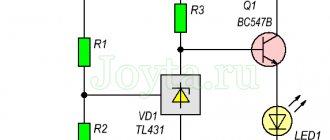
Each of the listed protective elements has advantages and disadvantages, but the general principle of operation is the same for them. It can be easily demonstrated using a TVS diode as an example (Figure 1). TVS is connected in parallel with the protected load. Under normal conditions, it is under reverse bias and has virtually no effect on the operation of the circuit. When a high-voltage pulse occurs, a reversible breakdown of the diode occurs. This limits the input voltage to the breakdown voltage level.
Rice. 1. Operating principle of TVS diode
There are many manufacturers of TVS diodes. One of them is the company Littelfuse. It has a rich history that began in 1927 with the production of protective fuses. Since then, the range of manufactured components has expanded significantly. Developers are now offered fuses, self-resetting PPTC fuses, protection thyristors, power semiconductor modules and much more.
One of the advantages of Littelfuse products is the highest quality, which is evidenced by the fact that since 1960, Littelfuse has been closely cooperating with the national aerospace agency NASA.
The range of Littelfuse TVS diodes is quite extensive, it includes various suppressors:
- Uni- and bi-directional;
- with constant reverse voltage levels 5…530 V;
- for surface mounting with power levels of 200…5000 W;
- for through-hole installation with power levels 0.4…30 kW;
- with current levels up to 15000 A.
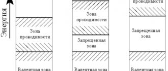
The properties of TVS diodes differ significantly from those of diodes and zener diodes. This is achieved through the use of a number of design features.
Design and principle of operation of TVS diodes
TVS diodes must have the following qualities:
- operation at reverse voltage must be stable;
- the level of reverse currents in the absence of interference should be minimal so as not to affect the operation of the rest of the circuit;
- the response speed to suppress fast interference should be minimal;
- the level of power dissipation to suppress powerful interference should be maximum;
It is easy to see that the requirements turn out to be quite contradictory. To increase the permissible power, you need to improve the quality of heat dissipation. This requires increasing the area of the pn junction. This, in turn, will lead to an increase in reverse currents. In general, the pn junction area of TVS is much larger than that of conventional diodes, and the reverse currents are also large.
A large pn junction area can be achieved by creating “flat” junctions. For bidirectional TVS diodes, the structure turns out to be symmetrical (Figure 2).
Rice. 2. Bidirectional protection diode design
The operating principle of the protective diode is based on the use of reversible breakdown. If a voltage with an amplitude greater than a certain VBR (breakdown voltage) level is applied to the TVS, a breakdown will begin with an avalanche-like increase in carriers. The current passing through the diode increases almost unlimitedly, and the voltage remains almost unchanged. As a result, the input voltage is limited. Thus, the TVS diode can be in two states: off and in limiting mode.
It's worth noting that TVS is not a perfect safety limiter. During a breakdown, as the current increases, the voltage across the diode increases, although only slightly. This leads to the fact that the clipping level depends on the power of the interference: the more powerful the interference, the higher the clipping voltage.
An increase in voltage with an increase in current is reflected in the slope of the current-voltage characteristic TVS (volt-ampere characteristic).
Diagnostics of the serviceability of the zener diode
A zener diode is a semiconductor element that stabilizes voltage in a fairly narrow range. At the same time, different currents, both large and small, can flow through it. The voltage stabilization range of a zener diode is usually limited to one hundred millivolts. Structurally, a zener diode is a diode, and in direct connection it works that way. It stabilizes the voltage when voltage is applied to it in reverse connection. You can check the serviceability of a zener diode with a multimeter in the same way as you can check the serviceability of a conventional diode.
Basic parameters of TVS diodes
The meaning of the main electrical parameters of TVS can be easily explained using its current-voltage characteristics (Figure 3). For unidirectional diodes it has an asymmetrical appearance, for bidirectional diodes it has a symmetrical appearance.
Rice. 3. I-V characteristics of TVS diodes
The TVS current-voltage characteristic differs from that of an ideal protective limiter. Firstly, when the TVS is turned off, it has quite large reverse currents. Secondly, the transition from the off state region to the limitation mode does not occur abruptly, but smoothly. Thirdly, the current-voltage characteristic in the limiting mode has a slope - the voltage depends on the current value.
Rice. 4. Dependence of peak power on pulse duration
In order to take into account all the listed features, the documentation for TVS diodes always provides characteristic values of the following currents and voltages:
Constant reverse voltage (VR, Stand-off Voltage), V – the maximum voltage that can be applied to the TVS without turning it on.
Leakage current (IR, Reverse Leakage Current), mA – reverse current flowing through the TVS at voltage VR and at a given ambient temperature (usually 25°C). In measurement circuits, it is important to select TVS with minimal leakage currents to avoid distortion of the useful signals. For example, when protecting the measuring circuits of resistive sensors with supply currents in the range of tens of milliamps, the TVS leakage current should not exceed tens of microamps.
Breakdown voltage (VBR, Breakdown Voltage), V, characterizes the magnitude of the breakdown voltage. In this case, the breakdown is determined by achieving a given value of the breakdown current IT at a given ambient temperature. The IT value is usually selected to be 1 or 10 mA.
The documentation, as a rule, does not provide a specific breakdown voltage value, but a certain guaranteed range.
Clamping Voltage (VC) characterizes the voltage drop across the TVS when a given peak current IPP flows at a given ambient temperature.
Maximum peak current (IPP, Maximum Peak Pulse Current), A – the current that the suppressor can pass without damage.
For unidirectional TVS, in addition to the listed parameters, forward voltage and current drop values (VF, IF) are given.
Peak power (PPPM, Peak Pulse Power Dissipation), W – the value of the maximum power at a given pulse duration and a given ambient temperature.
Peak power has a strong dependence on the duration of the applied pulse (Figure 4). When selecting a TVS for a specific application, you should carefully review the electromagnetic compatibility (EMC) standards. They indicate the amplitudes, durations and other parameters of possible interference.
Rice. 5. Dependence of peak power and peak current on ambient temperature
It was repeatedly stated above that the values of electrical parameters are indicated for specific temperature values. An increase in temperature leads to a decrease in the permissible values of peak power and currents (Figure 5).
It is important to mention additional TVS parameters.
Capacitance (C, Capacity), pF, characterizes the TVS’s own capacitance. This parameter is quite controversial.
On the one hand, the larger the capacitance, the more effective the interference reduction will be. In fact, interference limitation begins by charging the capacitance even before breakdown begins.
On the other hand, a large capacitance will be a negative factor when used in high-speed circuits, since it will introduce a delay in the propagation of signals.
Thermal resistance "junction to lead" (RuJL, Typical Thermal Resistance Junction to Lead) or thermal resistance "junction to environment" (RuJA, Typical Thermal Resistance Junction to Ambient). These parameters are important when considering the possibilities of increasing peak power by increasing heat dissipation. Heat dissipation is improved when using heatsinks and when mounted on a board.
Analysis of TVS features shows the presence of a number of shortcomings. On the one hand, TVS are not ideal voltage limiters. The degree of limitation depends on the interference power (Figure 6). On the other hand, the performance of TVS depends on the ambient temperature. However, in many cases, TVS are a better choice compared to other protective components such as arresters, varistors, thyristors.
Rice. 6. Features of limiting the input voltage pulse
Analyzing the results
When checking diodes (regular and Schottky) with a multimeter, you will get a certain result. Now we need to understand what it could mean. Signs that indicate the health of the semiconductor include the following:
- when connecting a part of the electrical circuit to the device, the latter will output the value of the available direct voltage in this element;
Note! Different types of diodes have different voltage levels, which is why they differ. For example, for germanium products this parameter will be 0.3-0.7 volts
- when connected in the opposite way (the probe of the device to the anode of the product), zero will be recorded.
If these two indicators are met, then the semiconductor is working adequately and the cause of the failure is not in it. But if at least one of the parameters does not correspond, then the element is considered unusable and must be replaced. In addition, it should be borne in mind that it is not a breakdown, but a “leakage” that is possible. This unpleasant defect can appear during long-term use of the device or poor-quality assembly. If there is a short circuit or leakage, the resulting resistance will be quite low. Moreover, the conclusion must be made based on the type of semiconductor. For germanium elements, this indicator in this situation will range from 100 kilo-ohms to 1 mega-ohm, for silicon - thousands of mega-ohms. For rectifier semiconductors, this figure will be many times higher. As you can see, it is not so difficult to assess the performance of semiconductors in any electrical device on your own. The above principle is suitable for testing diode elements of various types and types. The main thing in this situation is to correctly connect the measuring device to the semiconductor and analyze the results obtained.
Comparison of characteristics of protective voltage limiters
To determine the most optimal areas of application for TVS diodes, we will qualitatively compare them with other types of protective voltage limiters produced by LittelFuse. Such limiters include gas-discharge lamps, SIDACtor® protective thyristors, and varistors.
The analysis should consider the main operational characteristics: peak current levels, ranges of available clamping voltages, accuracy of clamping voltages, intrinsic capacitance, emissions control efficiency, clamping voltage, ratio of size to maximum current load (Table 1).
Table 1. Comparative analysis of protective voltage limiters
| Parameter | Gas arresters | SIDACtor® protection thyristors | Varistors | TVS |
| Peak current level | high | average | high | average |
| Minimum switching voltage, V | 75 | 8 | 6 | 6 |
| Turn-on voltage accuracy | low | high | low | high |
| Surge Control Efficiency | average | high | average | high |
| Typical capacitance, pF | ~1,5 | ~30 | ~1400 | ~100 |
| Peak current/size ratio | low | average | high | average |
| Response time | big | average | big | small |
The comparison shows that all limiters have their own characteristics and specifics. For this reason, each of them finds its own area of application.
Gas arresters are used to protect equipment from the most powerful interference. For them, peak currents amount to thousands of amperes. In this case, the number of protective operations turns out to be quite large. Among the disadvantages are the high voltage in the limiting mode and low performance. This does not allow the use of arresters for low voltage circuits. Another disadvantage is the large dimensions.
SIDACtor® thyristors are used to protect against less powerful interference. Compared to gas discharge lamps, they have better limiting efficiency. This means that the limiting voltage for them does not depend as much on the current as for arresters. Another advantage of thyristors is their reliability and long service life.
The main advantages of varistors are the high ratio of peak currents and dimensions. Thanks to the latter circumstance, varistors are optimal for creating the most compact solutions while protecting against powerful interference. They are used both in AC power supplies and in protecting low-voltage DC power lines (for example, in standard computer interfaces).
TVS diodes have the lowest clamping voltages and the fastest response times. Its accuracy turns out to be the best among all the listed protection devices. These factors make it possible to use TVS not only to protect power lines, but also to protect signal and even logic lines.
Rice. 7. Examples of application of TVS diodes
If we analyze the typical areas of application of TVS diodes, the following main groups can be distinguished among them (Figure 7):
- power electronics: (DC power supplies, motor drivers, inverters, and so on);
- telecommunication systems;
- control circuits (protection of outputs and inputs of operational amplifiers, transistor gates, input and output lines, including logic signal lines, and so on);
- digital interfaces (USB, RS-485, RS-232, CAN and others).
Littelfuse produces a wide range of TVS protection diodes for various applications.
LED testing
Testing LEDs is practically no different from testing rectifier diodes. How to do this was described above. We check the LED strip (more precisely, its SMD elements), infrared LED, and also laser LED using the same method.
Unfortunately, a powerful radio element of this group, which has a higher operating voltage, cannot be tested using the indicated method. In this case, you will additionally need a stabilized power source. The testing algorithm is as follows:
- We assemble the circuit as shown in the figure. The power supplies are set to the operating voltage of the LED (indicated in the datasheet). The measuring range on the multimeter should be up to 10 A. Note that you can use the charger as a power supply, but then you need to add a current-limiting resistor;
Measuring the rated current on an LED
- measure the rated current and turn off the power supply;
- set the multimeter mode, which allows you to measure DC voltage up to 20 V, and connect the device in parallel to the element under test;
- turn on the power supply and remove the operating voltage parameters;
- We compare the data obtained with those indicated in the datasheet, and based on this analysis we determine the performance of the LED.
Review of TVS diodes from Littelfuse
The TVS series produced by Littelfuse are distinguished by high performance characteristics and are available for various types of installation (Figure 8).
- TVS series of low and medium power surface mount (SMF, SMAJ, P4SMA, SMA6J, SMA6L, SACB, SMBJ, P6SMB, 1KSMB, SMCJ, 1.5SMC, SMDJ, 5.0SMDJ) have four housing options. They are designed to absorb emissions up to 5000 watts.
- TVS series of low and medium power through-hole mounts (P4KE, , SAC, P6KE, 1.5KE, LCE, 3KP, 5KP, SLD) are available in four housing options and have a peak power of up to 5000 W.
- TVS high power through-hole series (15KPA, 20KPA, 30KPA, AK1, AK3, AK6, AK10, AK15) are used to protect against high voltage surges up to 30 kW.
Littelfuse also produces specialized series of suppressors for automotive applications. They are able to work in the most severe conditions.
Rice. 8. Options for housing versions of TVS diodes produced by LittelFuse
The names of Littelfuse suppressors are unified and consist of five components: series name, voltage rating, polarity (unidirectional/bidirectional), voltage accuracy, packaging type (Table 2).
Table 2. Names of TVS diodes produced by LittelFuse
| Naming structure | ||||
| 1 | 2 | 3 | 4 | 5 |
| P6KE | 6.8 | C | A | B |
| Series | Voltage value | Polarity | Voltage accuracy | Package |
| SMAJ – 400 W | Constant reverse voltage value | C = bipolar | A = 5% | B – Bulk Pack |
| SMBJ – 600 W | ||||
| SMCJ – 1500 W | ||||
| SA – 500 W | ||||
| LCE – 1500 W | ||||
| 5KP – 5000 W | ||||
| P4SMA – 400 W | Breakdown voltage value | |||
| P6SMBJ – 600 W | ||||
| 1KSMBJ – 1K W | ||||
| 1.5SMC – 1.5 kW | ||||
| P4KE – 400 W | ||||
| 1.5KE – 1.5 kW | ||||
The voltage rating for a series range indicates the minimum constant reverse voltage value. For some series, the name indicates the rated breakdown voltage.
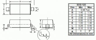
Littelfuse surface mount TVS diodes are designed for compact low to medium power surge protection circuits. All series have an operating temperature range of -65…150°C.
For portable devices that are critical to the dimensions of electronic components, unidirectional TVS of the SMF series are ideal. They are produced in SOD-123 cases, the length of which does not exceed 3.9 mm and the width is less than 2 mm. Moreover, their peak power is 200 W.
Representatives of the SMAJ and P4SMA series have a peak power of 400 W. Available in both unidirectional and bidirectional versions. Both series use the standard DO-214AC housing.
The SMA6L series diodes have the same housing. However, their power is already 600 W. The series range consists of only two representatives with constant reverse voltage levels of 5 and 12 V.
The SMA6L series has the same peak power as the SMA6J, but the choice of DC reverse voltage levels is much wider - 5...80 V.
The SMA6L and SMA6J series consist of unidirectional diodes only.
The SACB series has an interesting feature - TVS and a conventional rectifier diode are integrated into one package. This makes it possible to use SACB in AC voltage circuits. However, it is worth remembering that to limit pulses of positive and negative polarity, it is necessary to use two parallel SACBs connected in different polarities.
The SMBJ, P6SMB series have the same peak power as the SMA6L and SMA6J series, but the range of available DC reverse voltage levels for them is significantly wider, it reaches 440 and 490 V, respectively. Additionally, SMBJ and P6SMB run in both unidirectional and bidirectional configurations.
The highest peak power among TVS in the DO-214AA package is possessed by representatives of the 1KSMB series (up to 1000 W).
The SMCJ and 1.5SMC series are available in the DO-214AB package and have a peak power of 1500 W. Both series are available in unidirectional and bidirectional versions.
The SMDJ and 3.0SMDJ series have 3000W power and a small range of available switching voltages.
The 4.0SMDJ24A series consists of one representative with a constant reverse voltage of 24 V.
The representatives of the 5.0SMDJ series have the highest peak power of 5000 W.
Table 3. TVS diodes for surface mounting
| Name | Frame | Constant reverse voltage, V | Breakdown voltage min., V | Limiting voltage at maximum peak current, V | Peak power, W | Operating temperature range, °C |
| SMF | SOD-123 | 5,0…54 | 6,4…60,0 | 9,2…87,1 | 200 | -65…150 |
| S.M.A.J. | DO-214AC | 5,0…440 | 6,4…492,0 | 9,2…713,0 | 400 | |
| P4SMA | DO-214AC | 5,8…495 | 6,45…522,5 | 10,5…760 | 400 | |
| SMA6J | DO-214AC | 5,0…12 | 6,4…13,3 | 9,2…19,2 | 600 | |
| SMA6L | DO-221AC | 5,0…85 | 6,4…94,4 | 9,2…137,0 | 600 | |
| SACB | DO-214AA | 5,0…50 | 7,6…55,5 | 10…88,0 | 500 | |
| SMBJ | DO-214AA | 5,0…440 | 6,4…492 | 9,2…713,0 | 600 | |
| P6SMB | DO-214AA | 5,8…495 | 6,45…522,5 | 10,5…760,0 | 600 | |
| 1KSMB | DO-214AA | 5,8…136 | 6,45…171,0 | 10,5…246,0 | 1000 | |
| SMCJ | DO-214AB | 5,0…440 | 6,4…492 | 9,2…713,0 | 1500 | |
| 1.5SMC | DO-214AB | 5,8…495 | 6,45…522,5 | 10,5…760,0 | 1500 | |
| SMDJ | DO-214AB | 5,0…170 | 6,4…242,0 | 9,2…356,0 | 3000 | |
| 3.0SMC | DO-214AB | 20…30 | 22,2…36,7 | 42,0…70,0 | 3000 | |
| 4.0SMDJ24A | DO-214AB | 24 | 26,7 | 38,9 | 4000 | |
| 5.0SMDJ | DO-214AB | 12…170 | 13,3…189,0 | 19,9…275,0 | 5000 |
TVS diodes of low and medium power are output analogues of the surface-mount families discussed above (Table 4). The LCE series is worth special mention.
Table 4. Low and medium power TVS diodes for surface mounting
| Name | Frame | Constant reverse voltage, V | Breakdown voltage min., V | Limiting voltage at maximum peak current, V | Peak power, W | Operating temperature range, °C |
| P4KE | DO-41 | 5,8…495 | 6,45…522,5 | 10,5…760 | 400 | -65…150 |
| DO-15 | 5,0…180 | 6,4…200,0 | 9,2…289,0 | 500 | ||
| S.A.C. | DO-15 | 5,0…50 | 7,6…55,5 | 10…88,0 | 500 | |
| P6KE | DO-15 | 5,8…512 | 6,45…570,0 | 10,5…828,0 | 600 | |
| 1.5KE | DO-201 | 5,8…512 | 6,45…570,0 | 10,5…828,0 | 1500 | |
| LCE | DO-201 | 6,5…90 | 7,22…100,0 | 11,2…146,0 | 1500 | |
| 3KP | P600 | 5,0…220 | 6,4…244,0 | 9,2…371,0 | 3000 | |
| 5KP | P600 | 5,0…250 | 6,4…277,0 | 9,2…425,0 | 5000 |
TVS of the LCE series, like the SAC and SACB series, are TVS and rectifier diode integrated in one package. But, compared to SAC, LCE diodes have higher peak power (1500 W) and a wider range of available breakdown voltages.
High power TVS diodes are available only in lead versions (Table 5).
Table 5. High power TVS diodes for surface mounting
| Name | Frame | Constant reverse voltage, V | Breakdown voltage min., V | Limiting voltage at maximum peak current, V | Peak power, W | Operating temperature range, °C |
| 15KPA | P600 | 17…280 | 18,99…312,8 | 29,3…454,5 | 15000 | -65…150 |
| 20KPA | P600 | 20…300 | 26,81…335,1 | 36,8…483,0 | 20000 | |
| 30KPA | P600 | 28…288 | 31,28…334,0 | 50,0…484,0 | 30000 | |
| AK1 | Radial Lead | 76 | 85 | 140 | – | -55…150 |
| AK3 | Radial Lead | 15…430 | 16,0…440,0 | 28,0…625,0 | – | |
| AK6 | Radial Lead | 30…430 | 32,0…440,0 | 90,0…625,0 | – | |
| AK10 | Radial Lead | 30…430 | 32,0…560,0 | 58,0…750,0 | – | |
| AK15 | Radial Lead | 58…76 | 64,0…85,0 | 110,0…150,0 | – | -55…125 |
| SLD | P600 | 10…36 | 11,8…40,0 | 19,0…60,1 | 2200 | -55…150 |
The 15KPA, 20KPA, 30KPA series have a peak power of 15 kW, 20 kW and 30 kW, respectively. However, the minimum values of constant reverse voltage for them exceed 20 V. The exception is the 15KPA series, for which the reverse voltage value is from 17 V.
The AKx series has a radial pin arrangement and a large junction surface. They are optimized for the flow of huge currents of up to 1 kA (AK1) and up to 15 kA (AK15). In the first half of 2015, it is expected to release a product with a current of up to 30 kA. At the same time, the current-voltage characteristic of these TVS, taking into account the response to powerful pulses, has a pronounced loop. These diodes can be connected in parallel to increase the total power.
The SLD series is optimized for automotive applications and has a peak power of 2.2 kW.
A huge selection of different TVS allows the developer to find the optimal component for his application. Littelfuse engineers offer an algorithm to determine the appropriate diode based on the application.
Algorithm for selecting Littelfuse TVS diodes:
- Determine application features: voltage type (AC/DC);
- the need to use unidirectional or bidirectional TVS;
- rated voltage of the protected line;
- maximum value of limiting current;
- maximum permissible limiting voltage for the load;
- Operating temperature range;
- type of component installation (surface/through holes).
The diode reverse voltage value must be greater than the rated voltage of the circuit. Otherwise, the diode may turn on even in the absence of interference.
The value of currents and powers can be determined taking into account the impedance of the protected circuit. When calculating, as a rule, they are based on the interference parameters specified in the noise immunity standards.
The limiting voltage must not exceed the maximum permissible voltage value of the protected line.
- After selecting a diode based on performance characteristics, a test should be carried out. It is necessary to ensure that all specifications meet the requirements over the entire operating temperature range.
- Check that the selected TVS complies with the restrictions on overall dimensions and type of installation.
- Conduct testing using prototypes. Developers can contact the official distributor of Littelfuse in Russia - the COMPEL company.
How is the check carried out?
To check a semiconductor using a tester, you need to make sure that the multimeter has a diode test mode. After this, the work algorithm will be as follows:
- the red probe is inserted into the socket marked “VΩmA”;
- black – to the “COM” connector;
- select the mode for measuring resistance;
- the end of the red probe is connected to the anode, and the black one to the cathode;
- readings of changes in direct resistance are taken.
After all the operations performed, we can draw a conclusion about the performance of the semiconductor.
Checking the diode bridge
In a number of situations, it is necessary to check the condition of the diode bridge. It is a system of 4 diodes connected in such a way that the alternating voltage supplied to the two soldered components is converted to direct voltage.
The measurement algorithm is very similar to the classic method for testing a diode. However, there are also some nuances, namely the presence of 4 connection options depending on the pin number. The following combinations are usually called:
Analysis of results
Having received the test result, we can conclude that the semiconductor is serviceable. Signs of diode performance are:
- Coincidence of the forward voltage value displayed on the display when the element is connected to the tester with the indicators for a given type of diode.
- The zero value produced by the multimeter when connected in reverse.
If these parameters are observed, one can judge the working condition of the diode and the presence of a breakdown elsewhere. If one of the indicators does not meet the requirements, the semiconductor is considered non-working and must be replaced.
Checking diodes for serviceability using a tester is not so difficult on your own. A large assortment of multimeters on the market will allow you to choose a completely budget model, which will allow you to assess the performance of the diode in the circuit of any household electrical appliance.
How to test a diode with a multimeter without unsoldering it
Checking the Schottky diode is carried out without unsoldering it from the circuit, since this type of semiconductor is placed in a double case with a common cathode. So the measurement in this case can be done “on the spot”.
The same difficulties can arise when checking an LED. In some cases, it is necessary to evaluate a semiconductor without soldering it. Standard multimeter probes are not suitable for this, so you will have to make a special device that allows you to reach the electrodes in the circuit.
All work will include the following operations:
- On each side of a small foil fragment of PCB it is necessary to apply a small amount of solder on which the wires will be fixed.
- Straighten paper clips or small pieces of steel wire, which will then be soldered to the textolite gasket. Secure the entire structure with electrical tape.
- Prepare a multimeter with transistor testing mode.
- Connect the designed adapter to the tester.
- Place the probes on the legs of the semiconductor located in the circuit.
- To inspect.
Literature
- TVS Diode Devices. Transient Voltage Suppression. PRODUCT CATALOG & DESIGN GUIDE. 2013, Littelfuse.
- Electronics Circuit Protection. Product Selection Guide. 2013, Littelfuse.
- Documentation for the components was taken from the official Littelfuse website https://www.littelfuse.com/.
Obtaining technical information, ordering samples, ordering and delivery.
PulseGuard - low-capacity chip suppressors for ESD protection
Electrostatic discharge (ESD) is a type of electrical transient that poses a serious threat to sensitive electronic circuits. The most common cause of ESD is friction between dissimilar materials.
ESD interference potential can reach levels of up to 15,000 V, which can cause catastrophic damage to electronic components in a circuit.
PulseGuard® is a family of ESD suppressor chips developed by Littelfuse for low voltage signal circuits. These arresters, made from polymer composites, have extremely low capacitance (<0.12 pF), low leakage current (<1 nA) and fast response time (<1 ns), making them ideal for use in high-speed data transfer applications : IEEE1394, USB, HDMI, DVI, eSata, Ethernet.
These suppressors provide reliable protection against ESD without distorting the signal passing along the protected lines. PulseGuard® suppressors are selected when the application requires ESD protection only (IEC 61000-4-2), or data and signal line protection only, or where the application has stringent requirements for low introduced stray capacitance.
The PulseGuard® family consists of the PGB1 and PGB2 series. Suppressors of sizes 0201 and 0402 are a single bidirectional TVS diode with an operating voltage of 12 V; for size 0603 this parameter is 24 V. Suppressors in the SOT-23 package are designed for an operating voltage of 24 V and consist of two symmetrical (bidirectional) TVS diodes .
The low capacitance of PulseGuard® suppressors allows for excellent response speed and insertion loss performance up to 10 GHz.
•••