Once normal voltage is restored, the engine will not start spontaneously. Typical schemes for controlling an IM with a wound rotor.
Control circuit for an asynchronous motor using dynamic braking.
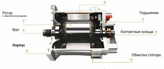
The winding on the rotor is switched using graphite brushes; only one of the frames is energized at a time, with a magnetic field perpendicular to the field of the stator winding. When the set level is reached, the relay will operate again and open the RDmax contact. Magnetic starter control circuits
Contactor K provides minimum voltage protection.
The engine is stopped by pressing the button SВ3, which will disconnect all contactors from the network and coast down the engine.
The process of engine braking by coasting begins under the influence of the load torque on its shaft. In Fig.
These are asynchronous motors with single-phase or three-phase power supply and commutator devices.
Servo drive The device allows precise control of the angular position, speed and acceleration of an actuator by controlling a synchronous electric motor, usually a PMSM. Regulating the speed of the working body of a machine or mechanism. reverse motor connection diagram
Our VKontakte group
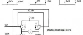
The disadvantages include the risk of a short circuit when supplied to two inputs; double H-bridge assembled on a low-power chip. But the relay does not immediately release its armature; this will happen after the time delay has expired. The F1 circuit breaker eliminates the possibility of one phase being broken from the protection being triggered during a single-phase short circuit, as happens when installing fuses in Fig.
For the operating principles of the circuits, see: When overloads occur in the motor circuit, an increased current occurs, which passes through thermal relays PT1, PT2.
The circuit returns to its original position.
It is this method that combines ease of implementation and sufficient power indicators, but does not involve simultaneous supply to two units. At the same time, relay P7 is activated, which with its contact energizes the solenoid valve SV - the compressor cavity communicates with the main line.
It follows from the diagram that a resistor Re is included in the circuit of contactor K, it reduces the voltage on the coil K and thereby reduces its heating after the contactor is activated, the voltage on it can be lowered. Photos of electric motor circuits Typical configurations and principles of operation of electric motors There are two most common types of motors, the connection of which can be made without additional parts.
The stepping mode of engine operation creates favorable setup conditions.
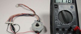
Checking the wire outputs and housing for short circuits will protect against accidents. Determining the beginning and end of the windings of a three-phase electric motor (simple method)
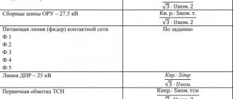
See also: Energy passport of a consumer of fuel and energy resources
Regarding mixed field coils
The collector units have two coils connected in series and in parallel. Often one of the coils has a much greater magnetizing force, since it acts as the main one. And the second one is additional. You can find matched and counter coils. And depending on this, the strength of the magnetic fluxes will be equal to the difference in the magnetic forces of each winding.
When the characteristics of motors are switched on in reverse, their performance will be closer to the same performance of electrical equipment that has parallel and series excitation. It turns out that such inclusions are relevant if you need to ultimately obtain a constant speed or increase them when the load increases.
Commutator motor braking circuit
Why can we consider their price justified? There are no magnets, which means they won't become obsolete. Even during abnormal operation, they are unlikely to fail. The control is dynamic and simple, low speed with high torque.
Typical control schemes for electric drives with asynchronous motors
In asynchronous single-phase motors, the winding on the rotor is short-circuited, and its design resembles a squirrel wheel. To turn off the engine, the stop button SB2 is pressed, the KM contactor loses power and disconnects the engine from the network. To exclude the possibility of simultaneous connection of the stator to sources of alternating and direct current, the circuit uses a standard blocking using breaker contacts KM and KM1, connected crosswise in the coil circuits of these devices. After starting the M1 engine, normal parameters of the brine and cooling water should be established, as indicated by the contacts: DTR brine temperature sensor; PP brine flow switch; The RD pressure switch opens its contact if the pressure in the line decreases or increases too much.
In this case, switch M2 is also turned off. To control drives, electrical switching devices are used, such as automatic and non-automatic switches, contactors and magnetic starters.
Automated control schemes In Fig. Electrical interlocks to prevent the simultaneous activation of two contactors are carried out using break contacts KM1 and KM2, Figure 6, b. The second closed contact P1 turns on the electromagnetic valve for blowing off the EMF.
The air gap between the inductor and the armature is only 1 mm. In the normal off state, the rotor of the electric motor is released under the action of a spring drive. Point P is the starting point. If the M1 electric motor stops, the same contact will automatically turn off the M2 motor.
Blog Search
When overloaded, the maximum current relay RM is triggered and turns off L1, L2 with its contact. Scheme of single-stage IM start-up as a function of current and dynamic braking as a function of rotation speed Scheme Fig.
This protection is called zero or zero blocking. When the liquid level in the supply tank drops below the minimum level, the RDmin relay closes.
If it is necessary to start the electric motor independently when testing the mechanism, there is a Q3 switch in the control circuit, which must first be closed. The photo shows a diagram of connecting such an electric motor to power B through a simple closing switch. The main disadvantages of squirrel-cage asynchronous motors are large starting currents, times higher than the rated current, and the inability to smoothly change the motor rotation speed using simple methods. Engine control scheme from two and three places
Model range of regulators
Let's look at examples of some devices that use different methods of regulating the operation of DC electric motors.
PWM 3A 80W
The device is implemented in several modifications, the voltage levels of which start at 12V and reach a level of 28 volts. The device is an adjustable, reversible type; the design includes a potentiometer with switch capabilities. The switching cable is 15 cm long, the input power range is DC6-28V. The package includes a reversing driver switch.
Motor Speed Control PWM MACH3 Speed Control
The model is a current regulator, the rated power range of which varies from 12 to 110V. There are also more powerful versions designed to work with 300 volt networks. The rated current of adjustable motors should not exceed 5 amperes. It features high response speed and compact design.
Motor Speed Control PWM MACH3 Speed Control
Electric drive control circuits
Electric drive diagram of a freon refrigeration unit In Fig.
If one of the electrified valves is faulty, the intermediate PIT relay breaks the automatic control circuits for hydraulic elevator pumping units.
To connect to a single-phase network, a transition capacitor is required, but in this case there will be losses in power and engine speed. At the output of the logic circuit, command relays are included, which send commands to the control circuit of the electric drives of the automatic stacker mechanisms. At the end of braking, when the rotation speed is close to zero and the rotor EMF decreases, the KV relay will turn off and, with its break contact, open the circuit of the KM2 contactor coil.
But these devices, despite their simplicity and reliability, are manual control devices. The motor receives reduced voltage. In this case, switch M2 is also turned off. When the stator windings are disconnected from the network, the rotor of the electric motor with a working mechanism, for example a circular saw of a sleeper cutter, continues to rotate for a relatively long time by inertia.
See also: Electrolaboratory registration
These circuits are widely used to control non-reversible electric drives of conveyors, blowers, fans, pumps, wood processing and sharpening machines. After starting the M1 engine, normal parameters of the brine and cooling water should be established, as indicated by the contacts: DTR brine temperature sensor; PP brine flow switch; The RD pressure switch opens its contact if the pressure in the line decreases or increases too much. In addition to mechanical interlocking, the circuit uses typical electrical interlocking used in reversible control circuits. If the temperature in the premises rises above the set one, the DOT contact closes, relay P2 is activated and the compressor starts.
When each button is pressed, the circuit of one of the starters is closed, and the circuit of the other is simultaneously opened. In accordance with the rules for the technical operation of lifting mechanisms, when turned off, the drive and lifting mechanism must be reliably braked. The circuit includes a control unit for thyristors CU and a relay contact control unit. Pressing the SB2 button simultaneously closes the power circuit of the contactor KM2 coil, which, when turned on, reconnects the motor to the network, but with a different phase rotation of the mains voltage on the stator. The start begins after moving the contact brush to pin 1.
We also recommend reading
An animation of the processes occurring in a circuit with two starters is shown below. The motor stator and the electromagnet winding Y will be simultaneously connected to the network. For this purpose, the control circuit of the magnetic starter KM2, which starts and stops the electric motor M2, includes a closing auxiliary contact KM1, connected to the starter KM1. This allows you to reduce energy consumption and motor wear, prevent overheating and provide a number of additional opportunities for connecting automation.
At the same time, the NO contact of the RP relay signals to the control center. To accelerate it, the furnace bath is rotated relative to the axis by 40 to the left and right and in each of the extreme positions new wells are melted, which ultimately leads to the collapse of the charge in the furnace and the acceleration of the most difficult from an energy point of view mode of melting the charge. When you press the button, the normally closed contact is switched off first, and then the normally closed contact is switched on. In this case, it is connected from any two phases, for example, from A and B. The switch can have several positions to select different methods of connecting the electric motor, which can allow you to reduce the starting voltage, select the direction and speed of rotation. How to Read Electrical Diagrams
Methods for adjusting commutator motors
It is necessary to consider the question of how to adjust the speed when a 220V AC commutator motor is running. The thing is that the speed at which a 220-volt motor rotates simply depends on the amount of voltage that is supplied. In this case, any means of reversing are suitable: household regulators, buttons, factory control boards, laboratory autotransformer.
Each of these methods has many flaws. The speed decreases and along with it the engine power decreases. Sometimes they stop with their hand. The tachogenerator wins significantly out of all possible options. But it is better to install them in factories. If there are deviations in the speed of rotation of the engine, the triac will transmit power to it, which has already been adjusted. When the engine speed control is integrated into the circuit, no power losses will occur.