Those houses that are connected to old power lines are acutely affected by power surges in the network. Due to such violations, household appliances often break down. The problem can be solved by simply installing a voltage relay. Let's analyze what such a device is and how to choose it wisely. We’ll also figure out how to connect the device to your home network.
Control device in a niche Source hsto.org
Why do you need to control voltage?
The device has an official name - voltage control relay. But the middle word is often discarded. And professionals often call the device among themselves “zero break protection.” After all, it falls into the category of protective automation. Let's figure out why we need a voltage relay.
The average consumer is accustomed to the fact that all electrical appliances are powered from a network whose voltage is 220 V. In fact, the voltage variation in the outlet is allowed with a plus or minus of 10 units. And all household equipment is produced so that it can work with a reserve. That is, in the range from 170 to 265 V.
But worn-out electrical networks sometimes produce spikes of up to 380 volts. Or they experience a voltage drop of up to 70 units. In both cases, nothing good happens. With an extreme instantaneous increase in parameters, in houses equipped with automatic protective equipment, the fuses will simply blow out. And if the latter are absent, then the action scenario can go in two ways.
Burnt fuse Source p-advice.com
Fuses will blow if there are any in a working TV, computer or microwave. In their absence, any device is guaranteed to fail if it was used at that moment. Moreover, it could easily catch fire. And this is already fraught with a fire in the house.
It would seem that too low voltage in the network cannot threaten anything terrible. Well, the light bulb in the lamp will burn dimly. Or the iron will not heat up and things will remain unironed. But this is not true.
First of all, all household appliances that have a compressor will suffer. The latter simply will not start at low voltage. This is fraught with the fact that the electric motors of the equipment quickly begin to overheat. And having reached a critical state, they completely fail.
See also: Catalog of companies that specialize in complex installation of internal engineering systems
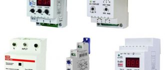
Consumer demand for relays from various manufacturers
There are a large number of relay manufacturers; among domestic ones, the products of FSUE NPP START in Veliky Novgorod, relay REP-26 004, REP-26 002, REP-26 003, are often used.
RP-21M, RP-21MN are produced at the Moscow and Cheboksary LLC "PKF Experimental Power Equipment Plant" in Cheboksary. These products are in good demand and are even counterfeited by Chinese competitors.
Tip No. 2 When installing Chinese models, be sure to test the contacts with a multimeter or other devices, in the initial state and after the relay is activated. It happens that the contacts stick, do not close or do not open.
On the right side is a variant of a Chinese fake.
Professionals recommend using imported models from manufacturers
ABB, Schneider Finder, Siemens, Electric, Relpol.
The wear resistance of the contacts of these products is much higher; failures in the control system of complex equipment can lead to production stops and costly repairs. Therefore, it is more rational to use more expensive but reliable relays.
Causes of problems
There are three factors that cause voltage drop:
- When the phase is shorted to neutral, 380 Volts will appear in the socket.
- If a zero break occurs and the load in the network is low, then the voltage will sharply tend to the peak.
- There may be a voltage imbalance in the phases.
Low voltage Source uk-parkovaya.ru
In the latter case, an unevenly distributed load leads to the fact that the busiest line will suffer. The voltage will drop to critical. And this is fraught with local problems in the technology itself. And, as a rule, if there is no surge protection relay on the line, then the refrigerator or air conditioner will be the first to suffer.
In rare cases, electricians are to blame for a zero break. The wire can be damaged due to inexperience and carelessness. More often the latter fades away from old age. The provided protection will de-energize the line and disastrous consequences will not occur. There will be temporary inconvenience until the network is restored.
But, if there is no voltage cut-off, then a real mess ensues in the house. In some rooms, the voltage in sockets drops to 50-100 units. In other apartments it rises sharply to 300-350. Moreover, the result is completely local and depends on the specific load on the home line.
A sharp increase in voltage Source uk-parkovaya.ru
As a result, some owners' household equipment simply stops working. Those less fortunate will have to take it for repairs. But after a critical power surge, it happens that repairing the device becomes unprofitable. And then all that remains is to buy a new one. And, as a rule, there is no one to file a claim with.
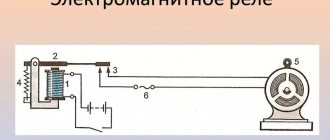
How protection works
The operating principle of a voltage relay is simple. The device has a built-in network load monitoring unit. Control parameters are usually set by the manufacturer. But the owner has the right to set his own limits.
The block is constantly busy measuring the voltage on the line. And if it deviates from the norm in any direction, then a signal is instantly sent to the executive module. The latter immediately switches off the load on the line, saving working devices.
But the measuring unit continues to operate in cyclic mode. After a certain period of time, the module takes readings from the line. If violations persist, then the automation is inactive. She waits for the next time period for measurements.
Voltage monitoring device Source prom.st
It can also be installed manually. Or leave the factory settings. When the measurements show the specified norm, the executive unit is also notified about this. And it closes the power contact, renewing the connection to external power sources.
Main technical parameters of intermediate relays
All relays, including intermediate ones, are evaluated according to the following parameters:
- Switched voltage value;
- Rated current value at switching contacts;
- Minimum switching current;
- Permissible short-term current through switching contacts;
- Interval of voltage value on the electromagnet coil;
- Power consumption of the switching coil;
- Closing time;
- Contact opening time;
- The wear resistance of contacts is assessed by the number of relay activations;
- The maximum permissible load power, which is connected through the relay contacts.
These are general parameters of technical characteristics; depending on the design and purpose, there may be additional ones. Let's look at specific technical characteristics using the example of REP - 26 different modifications.
| options | magnitude |
| Switching voltage range | AC 5–381 V DC 5–221 V |
| Rated current on contacts | 10.1 A9.1 A8.1 A6A |
| Minimum contact current | 0.06 A0.01A |
| Through current on contacts (A) | 161A |
| Interval of voltage changes in the control circuit | +5,1 %-15,1% |
| power consumption by the coil - at DC. current with 1-3 contacts - at DC. current with 4 contacts - with alternating current | 1.6 kV2.1 kV3.1 kA |
| Response time, no more. | 0.03 sec |
| Release time, no more. | 0.03 sec |
| Mechanical wear resistance. | 30 million triggers |
| Switching power - with alternating current - with direct current | 1.6kW3kW150W250W |
Selection of protective automation
Overvoltage relays can be classified according to three criteria. Pay attention to the location and dimensions. Take into account the capabilities of the device. As well as the number of phases in the electrical network. Due to these indicators, the installation of the device differs in many ways.
And when choosing protective automation, people usually pay attention to:
- operating range in volts;
- maximum power;
- passing current;
- speed of network shutdown when an alarm signal is given;
- delay before re-supplying electricity;
- presence of indication.
An important factor is the presence of manual settings. Many apartment owners are not satisfied with the parameters set by manufacturers. And they would like to independently set the upper and lower thresholds for triggering the automation.
Adjustable voltage control relay Source prom.st
Phasing
Since the power supply system may differ, the devices are divided into single-phase voltage control relays and three-phase ones. Apartments and most private cottages are equipped first. They work with networks with a voltage of 220 V.
Three-phase protection is mainly used in industry. For example, they protect machines that use several phases for their operation. Moreover, in some cases, phase synchronization is additionally controlled.
Three-phase relays are also used in private homes if the voltage circuit has 380 Volts. But the device has a feature that has a negative effect when used at home. The protection is triggered if oscillation occurs in any of the three phases, which is not critical on a private line. But for production, such a safety net is often a plus. Although in many cases you can easily do without it.
Classification of types of intermediate relays
There are many options, let's look at the main varieties:
Relays are divided by switching type
- Minimum - reduce a certain parameter to a set threshold;
- Maximum – increases a certain parameter to a set threshold;
By functional purpose
- Combined - connecting a group of relays to solve a specific logical problem;
- Logical – work with the same parameters in discrete electrical circuits;
- Measuring – intervals of certain parameters are regulated.
By load control method
- Direct impact - relay contacts directly connect the load;
- Indirect influence - the load is connected through circuits of secondary elements.
By connection method
- Primary - connected directly to the circuit by contacts;
- Secondary - switched on through inductive or capacitive elements.
Intermediate relays in protection circuits have their own design features and are divided according to the following characteristics:
- Semiconductor - do not have switching contacts, the circuits are opened and closed by p-n-p and n-p-n junctions under the influence of control voltage. Varistors, thyristors, triacs and transistors are used as semiconductor elements.
- Induction - the control voltage in the winding is induced from an adjacent coil that is not connected by direct electrical contact;
- Magnetoelectric - the magnet occupies a stationary position in the structure, the coil with contacts on the frame rotates, closing or opening the circuit;
- Polarizing - work as electromagnetic direction of switching contacts will determine the polarity of the connection on the coil;
Video description
The video will show how a single-phase voltage relay works, which one is better to choose based on the test results:
Device dimensions
All products are divided into 3 types:
- Adapter for one socket. Protects only one device connected through it.
- An extension cord where there can be from one to six sockets. In this case, the protection extends to an entire group of devices.
- Bag holder for DIN rail. It is mounted in a common electrical panel and controls the entire electrical supply system of the apartment.
The latest version of a 220 V voltage relay for the home is not only the most functional. It is also the most suitable in terms of design, since all devices are hidden from view. And the devices from the first two points most often have large sizes. And most often it is not possible to make them more compact so that they do not spoil the interior of the home.
Basics and additional features
In most modern protective automatic equipment, voltage control is carried out by a microprocessor. Cheap analogues of relays operate on the basis of a conventional comparator. The microprocessor allows for precise adjustment of the device. Including stepless manual adjustment for response thresholds.
Surge protection device Source psk-remont.ru
Also, devices may have different indications. In simple designs, only a pair of LEDs are built in, which indicate the voltage at the output and input. All modern models have a display on the body that shows the voltage. It can also show specified response thresholds.
Available connection diagrams
In the panel, a single-phase voltage relay is mounted after the meter. It must be placed in the break of the phase wire. Because only the device should control the voltage. And cut off the phase if necessary.
There are two connection diagrams. It is more common to install relays under direct load. But you can connect an additional magnetic contactor to it. When installing the device, the main thing is not to confuse the connection of wires to the input and output. True, this is difficult to do, since there are only three terminals on the automation body, and they are all labeled - input, zero, output.
Devices with different rated power are available for sale. Therefore, there will be no problems in selecting the right one for your home network. But it is always possible to install several low-power relays using a parallel circuit. In this case, only its own group of electrical appliances is connected to each controller.
Design and principle of operation of the intermediate relay
This product can be compared to a miniature magnetic starter, the number of groups of contacts in which is determined by the circuit where it is used for its functional purpose.
Not in all circuits they can be used for switching power supply circuits; their main purpose is the transmission of control signals. This is due to the thin plates of the contact group; rare models are capable of passing operating currents above 10 A for a long time.
The classic design of a small-sized intermediate relay includes the following elements:
- The base on which all components are attached;
- Electromagnetic coil with core;
- A movable plate with a lever for displacing the movable group of contacts;
- The lever drive spring returns to its original state after removing the control voltage from the coil winding;
- Panel with a group of contacts;
- Terminals on the base for connecting wires to the switching and coil contacts.
As an example of a variation, one can cite the design of an intermediate relay in the control system of diesel locomotives.
How to set up devices
The simplest designs have preset response thresholds set by default by the manufacturer. As a rule, the operating range of the relay is from 170 to 265 V. The parameters may differ, so when choosing, you need to pay attention to them, since it will not be possible to reconfigure later.
Adjustable relays have 3 settings:
- The lower threshold for triggering is set.
- The maximum voltage value is selected.
- Sets the delay period before turning on again.
Connecting a voltage relay is a serious process. But setup requires even more responsibility. It is necessary to study all the household equipment used in the house. And only then set the thresholds. As for turn-on delays, a compromise will have to be found there.
If appliances with a compressor (refrigerator, air conditioner) have priority in protection, then the voltage re-supply time must be set to quite long. From a couple of minutes. And in some cases even bring it to five. This will protect the devices from sudden voltage surges.
Extension cord with controller Source prom.st
But if only a TV and a computer are protected, then a delay of only 10-20 seconds is sufficient. For adjustments, smooth regulators are provided on the body. Modern devices are equipped with convenient sensors.
Some experts recommend connecting a voltage stabilizer rather than a control relay. This is motivated by the fact that in addition to the functions of the latter, it also equalizes the voltage. Therefore, more reliable protection is obtained.
But the stabilizer has significant disadvantages:
- It makes noise when working.
- Takes up a lot of space due to its bulkiness.
- Does not allow fine tuning.
- Increases the network current and thereby creates a danger for unprepared wiring.
- If the grounding is broken, the voltage surge remains unattended.
- Its cost is much higher than a conventional relay.
Therefore, they are accustomed to using a voltage stabilizer only locally. For example, to protect only one refrigerator.
Explanation of the abbreviation of intermediate relays
To conveniently determine the functional purpose, number of contacts and other parameters, the relays have alphabetic and digital designations:
- P – intermediate;
- E – electromagnetic;
- 46 or (XX) – product series;
- 1 – pulse control signals.
Further designations may determine for what climatic conditions the product is adapted and the number of contact groups.
An example of how the symbols are deciphered
REP26-004A526042-40UHL4
- REP – electromagnetic intermediate relay
- Episode 26
- XXX – functional purpose and number of contacts
| appointment | Quantity | ||
| closing | opening | switching. | |
| 001 | — | — | + |
| 010 | — | + | — |
| 100 | + | — | — |
| 002 | — | — | ++ |
| 020 | — | ++ | — |
| 110 | + | + | — |
| 200 | ++ | — | — |
| 003 | — | — | +++ |
| 120 | + | ++ | — |
| 210 | ++ | + | — |
| 300 | +++ | — | — |
| 004 | — | — | ++++ |
| 220 | ++ | ++ | — |
| 310 | +++ | + | — |
| 400 | ++++ | — | — |
- 001 – means that the relay contains 1 switching contact, 010 – one breaking contact; 400 – four normally open contacts.
- A….D – wear resistance class of the materials from which the contacts are made;
- X – type of current in the winding of the electromagnetic coil, type of design for returning the mechanism to its original state,
1 – ~ current;
5 – direct current;
6 – direct current in the current coil;
- XX – two-digit digital code showing the design of mounting the relay housing on the surface and the method of connecting wires to the terminals:
| Code | connector | Wire connection method |
| 16 | —- | Solder |
| 18 | —- | "faston" |
| 76 | —- | seal |
| 21 | + | screw connections |
| 26 | + | solder |
| 78 | + | seal |
- XX – code indicating the magnitude, type of voltage, current in the coil winding
| Codes for electrical parameters of the closing coil | ||
| constant | ~ current 50 Hz | |
| 01…6 V 02…12 V 03…15 V 04…24 V 06…48 V 09…60 V 11…110 V 13…220V | 21…12 V 22…24 V 24…40 V 26…110 V 27…220 V 28…380 V 34…230 V 35…240 V | |
Codes from 01 to 13 indicate that the coils of these relays are DC with different voltages from 6 to 220V. Codes 21 to 35 indicate that the coils are rated for ~ I with U = 12…. 240 V frequency 50 Hz.
The last designation X indicates the presence of special elements in the design:
2 – manual relay switch;
5 – with manual manipulation and electronic relay position indicator for 24V products;
6 – with a manual manipulator and a diode to protect relays at 24V and less;
7 – the relay includes all three previously listed elements,
40 is the degree of protection from moisture and dust IP- 40...56..68;
UHL4 is a model for the corresponding climatic conditions, given for the north and middle latitudes. The letter “O” indicates that the product is adapted for the tropics.
REP26-004A526042-40UHL4 - this abbreviation indicates that the intermediate relay has 4 switching contacts with class A (wear resistance), direct current, contact connection with connectors, wires are secured by soldering, a 24 V coil, the design has a manual manipulator. Protection class IP – 40 for northern and middle latitudes.
Tip #1. Some people neglect the degree of protection of the product; relays have thin contacts and are sensitive to dust and humidity. Therefore, the degree of protection must be taken into account, especially in facilities with high humidity and dust. In explosive areas, it is recommended to use semiconductor products that do not spark during switching.
Despite the different designs and technical characteristics, all intermediate relays have basic common parameters by which compliance with the functional purpose is determined.
Briefly about the main thing
To protect home equipment from network overloads, it is necessary to install protective automatic equipment in it. You can use a regular relay that will control the voltage. The device will constantly measure the readings of the latter. And if you deviate from the set norm, independently disconnect from the power source.
You can provide protection to each individually connected household device. For this, special adapters and extensions are produced. But it is more reasonable to protect the entire home electrical network from overvoltage by installing one relay directly in the apartment’s electrical panel.
Connecting the automation is simple. The relay is installed immediately after the meter, breaking the phase wire. The main attention is paid to setting up the device. Reliable protection will be provided by setting upper and lower response thresholds. As well as the delay time before turning on again.