Automatic switches, also known as packets or automatic machines, are switching devices whose task is to supply current to the elements of the electrical network, and if its operation is disrupted, to automatically de-energize it. They are usually mounted in a distribution panel and allow you to protect the circuit from damage caused by excessive loads, voltage drops, and short circuits. In this material we will talk about how this equipment is classified, what are the features of its operation and how to correctly connect the machines in the electrical panel.
Classification of circuit breakers
Today, these devices are sold in a huge range. They differ from each other in the following characteristics:
- Main circuit current. It can be variable, constant or combined.
- Control method. The equipment can be operated manually or using a motor drive.
- Installation method. Devices can be plug-in, retractable or stationary.
- Type of release. These elements can be electronic, electromagnetic and thermal, as well as semiconductor.
- Body type. It can be modular, cast or open.
- Operating current indicator. Its value can range from 1.6 A to 6.3 kA.
Modern machines have a complex network protection mechanism. They have additional capabilities, which include:
- Possibility of opening an electrical circuit from a distance.
- Presence of signal contact groups.
- Automatic activation of the protective device in the event of a voltage drop to a critical value.
Step-by-step diagram for selecting a circuit breaker in the video:
Packers can have different standard sizes, and with their help you can protect electrical networks not only in apartments and private houses, but also at large facilities. These devices are produced both in Russia and abroad.
In domestic conditions, modular circuit breakers, small and lightweight, are most often used. They received the name “modular” due to their standard width, which is 1 module (1.75 cm).
In order to protect the electrical circuits of buildings, the following types of switches are installed:
- Differential.
- Automatic.
- RCD.
RCDs, as residual current devices are called for short, prevent electric shock to a person who touches the conductor, and prevent surrounding objects from igniting if there is an electricity leak, which can happen if the cable insulation is damaged.
Circuit breakers protect circuits from short circuits and allow you to turn the power on and off manually. The most advanced protective device is a differential circuit breaker. It combines the capabilities of a residual current device and a conventional circuit breaker. This package is equipped with built-in protection against too powerful electron flow. It is controlled by differential current.
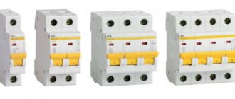
In single-phase electrical networks, single-pole and double-pole circuit breakers can be installed. The choice of package is influenced by the number of wires in the electrical wiring.
Design and purpose of the machine
Despite the name - “automatic”, this type of switch operates only in one direction - it opens the electrical circuit (if the nominal value is exceeded or there is an overload associated with the simultaneous activation of several powerful electrical appliances). There is only one way to turn on, that is, close the circuit - manually.
Unlike a simple single-key switch, an automatic device has a more complex structure. Schematically, the classic version (without an electronic unit) looks like this.
Circuit breakers: design and principle of operation
Before we consider the procedure for connecting circuit breakers in an electrical panel, let’s figure out how they are designed and on what principle they are triggered.
The product includes the following elements:
- Frame.
- Control system.
- Top and bottom terminals.
- Switching device.
- Arcing chamber.
Fire-resistant plastic is used as material for the manufacture of the housing and control system. The switching device contains moving contacts as well as fixed contacts.
An arc-extinguishing chamber is installed on a pair of contacts, which are the pole of the packetizer. When the contacts break under load, an electric arc occurs, which is extinguished by the camera. The latter consists of steel plates, insulated from each other and located at the same distance. The chamber plates help cool and extinguish the electric arc that appears during malfunctions. Machines can have one, two or four pairs of contacts.
Two-pole circuit breakers have two pairs of contacts: one is movable, the other is fixed.
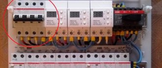
Such a switch is equipped with a position indicator, which makes it easy to find out whether the machine is on (red light) or off (green).
The operating principle of circuit breakers is clearly shown in the video:
Connecting machines in a three-phase network
In a three-phase network, three or four-pole circuit breakers are used. In the TN-C system, all three phases L1, L2, L3 are connected to the upper terminals of a three-pole circuit breaker, and the neutral wire is connected to the neutral bus of the electrical panel.
Connecting a three-pole circuit breaker in a TN-S network system with neutral and protective grounding
In the TN-S system with protective grounding PEN, three phases are connected to the upper terminals of a four-pole circuit breaker, and the blue neutral wire is to the upper terminal of the fourth pole of the input circuit breaker marked N. The yellow-green protective PEN wire is connected to the grounding bus of the electrical panel.
Release
To turn off the machine in case of emergency situations, the device is equipped with a release. There are several types of these mechanisms, structurally different from each other and operating on different principles.
Thermal release
Structurally, this element includes a plate pressed from two different metals with an unequal coefficient of nonlinear expansion, which is connected to the circuit under load and is called bimetallic. When the release operates, the flow of electrons passing through the plate heats it.
Since the expansion coefficient of the metal is less than that of the plate, it bends towards it. When the current rating exceeds the permissible value, the curved plate, acting on the trigger, turns off the machine. If the ambient temperature deviates from the norm, the switch also trips.
Magnetic release
This type of release is a coil consisting of an insulated copper winding and a core. Since load current flows through it, it must be connected to the circuit in series with the contacts. If the load current exceeds the permissible rating, the core will move under the influence of the magnetic field of the release and, through a disconnecting device, will open the contacts of the packet.
Selective circuit breakers with semiconductor releases
These devices are equipped with a special panel on which the machine's shutdown time is set. They provide a temporary delay in the event of a short circuit, which allows, in the event of an emergency, to turn off the emergency section without stopping the power supply to the facility.
A circuit breaker without a release is called a disconnector.
How to choose a machine?
Before you begin installing protective circuit breakers, you need to select them and also understand the intricacies of connection. People who want to know how to wire a circuit breaker ask various questions. For example, are the circuit breakers in the distribution board connected before or after the meter? Should an automatic input be installed? These and other connection nuances are of interest to users.
Basic parameters of circuit breakers
The characteristics of circuit breakers include:
- Rated current value (in Amperes).
- Operating voltage of the electrical network (in Volts).
- Maximum short circuit current.
- Ultimate switching capacity.
- Number of poles.
The maximum switching capacity is characterized by the maximum permissible value at which the switch is capable of operating. The PKS of household devices can be 4.5, 6 or 10 kA.
When choosing, they are most often guided by such basic indicators as short-circuit shutdown current, as well as overload current.
The cause of overload is the connection to the electrical network of devices with excessively high total power, which leads to exceeding the permissible temperature of contact connections and cables.
Taking this into account, it is necessary to install a packet in the circuit, the value of the shutdown current of which is not less than the calculated value, and better - if it slightly exceeds it. To determine the calculated current, you need to sum up the power of the devices that are supposed to be connected to the circuit (for each of them this indicator is available in the passport). The resulting number must be divided by 220 (the standard voltage value in a household network). The result obtained will be the value of the overload current. It should also be taken into account that it should not exceed the current rating that the wire can withstand.
The magnitude of the shutdown current during a short circuit is the indicator at which the circuit breaker is switched off. The short-circuit current is calculated when designing the line using formulas and reference tables, as well as using special equipment. Based on the obtained value, the type of protection is determined. At small sites and in household networks, type B or C machines are used.
Operation of safety switches
To connect the device correctly, you need to understand the principle of its operation.
The product consists of a housing, terminals, control system, communication device, and arc chute.
The devices are made from fire-resistant plastic. Some contacts can move, some are stationary.
The contact pair located on the pole of the machine has an arc chamber that controls the voltage. The chamber consists of plates that cool the electric arc that occurs during disturbances.
Several pairs of contacts can be installed in meter machines. The double-pole switch has 2 pairs of contacts, moving and stationary, and is equipped with an on indicator.
It is important to know! The release switches off the device in the event of an accident. The thermal release contains a plate that heats up under the influence of current electrons or when the air temperature changes, and bends towards the trigger mechanism, turning off the device.
A magnetic release consists of a coil that is connected in series to the contacts. In the event of an accident, the core in the coil moves under the influence of the magnet and opens the contacts.
The excess total power of connected devices causes an overload in the electrical network. Therefore, automatic meters for the electric meter are connected to the circuit, which are turned off when the current value is greater than the calculated one. The required value is determined by adding up the power of the devices that will be connected to the network, and dividing the resulting number by 220. This is the overload indicator. This is the size the wire must withstand.
The calculation of the value at which the machine will turn off in the event of a short circuit is made during the construction of the building, and then the type of protective device is selected.
Installing a circuit breaker in an electrical panel with your own hands
First of all, you need to decide on connecting the power wires, and only after that figure out how to connect the machine to the network. If you do not know whether the power conductors should be connected to the top or bottom of the package, please refer to the PUE requirements, which are the main guiding document for electrical installation work.
The Rules clearly state that the power cable must be connected to fixed contacts, and this requirement must be met in any circuit breaker connection diagram. In any modern device, the fixed contacts are located on top.
For installation you will need control devices and tools, which include:
- Assembly knife.
- Screwdrivers (phillips and slotted).
- Multimeter or indicator screwdriver.
So, how to connect the machine correctly? Let's consider the installation of circuit breakers in single-phase networks.
Two-phase and three-phase connections are more complex and it is advisable that they be carried out by a specialist.
Single-pole circuit breaker
The installation is carried out on a network where two cables are used for input: neutral (PEN) and phase (L). Such a system exists in old buildings. The supply conductor is connected to the input terminal of the machine, then from the output it passes through the meter, after which it is routed to the protective devices of specific groups. The supply neutral cable is also supplied to the PEN through an electric meter.
Application of one, two and three-pole circuit breakers on video:
Two-pole machine
We are considering the installation of a protective device in a single-phase network, where three conductors are used for input: phase, neutral and ground cable. The input terminals, designated on the device by numbers 1 and 3, are located at the top of the machine, and the output terminals (2 and 4) are at the bottom.
The power cable fits to input terminal 1 and is securely fixed to it. In a similar way, the neutral wire is attached to terminal 3. The phase passes through the electricity meter. Power is distributed evenly across groups of switches. From terminal 4, the neutral cable is connected to the N bus, passing through the meter and the RCD.
Connecting wires
Any circuit breaker is accompanied by a passport that states how to correctly connect the wires to its terminals. The document contains all the necessary information - from the cross-section of the cables and the type of their connection to the length of the stripped part of the conductor.
Stripping the ends of the wires for connecting household machines is done with a mounting knife about 1 cm. You can distinguish the conductors by their color markings:
- Phase cable – white or brown.
- Neutral wire – black, blue or light blue.
- The grounding conductor is green.
After stripping the end of the wire with a knife, it must be inserted into the contact clamp and secured with a fixing screw. The screws are tightened with a screwdriver. After fastening, the wire needs to be tugged a little to make sure it is securely fastened. If a flexible wire is used to connect to the package, then to increase the reliability of the connection, special tips should be used.
To ensure that the installation of machines in the electrical panel and the connection of cables to them are carried out correctly, you need to remember common mistakes and avoid them during operation:
- The insulating layer gets under the contact clamp.
- Too much force when tightening, which can lead to deformation of the body and, as a result, to breakage of the machine.
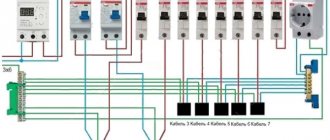
Often several protective devices are installed in a distribution board. To connect them, inexperienced specialists use jumpers.
In principle, this is not a mistake, but still in this case it is better to use a special tire cut to the required size - the so-called comb. With its help, the wires are connected to the packets in the required sequence.
How to connect machines after the meter
First of all, determine the required number of circuit breakers. The best option would be to share the load. One device is used for sockets, and the second for powering lighting.
An expensive option is to install a separate switch in each room. With this method, there will be machine boxes in each room, which does not always fit into the interior.
It is advisable to install meter machines with the help of an electrician who understands various types of meters, automatic switches and electrical connection diagrams. Using his knowledge, you can reduce material costs for electrical panel equipment, find out possible ways to save energy, and improve the power supply of connected devices.
Features of connecting SIP to the input circuit breaker
Self-supporting insulated wire is widely used to transmit electricity to the home network from overhead power lines instead of conventional cable. Despite all the advantages of this conductor, connecting the SIP to the circuit breaker should not be done directly, since during operation the aluminum begins to “float” and the insulation burns. Ultimately, this leads, at best, to failure of the machine, and at worst, to a fire. The easiest way to avoid such trouble is to connect the SIP to the machine through a special adapter sleeve.
This device ensures the transition from aluminum wire to copper. You can buy it in a specialized store.
Step-by-step installation of the machine is shown in the following video:
How to replace a machine in a panel
The expression “replacing a circuit breaker with voltage relief” means that not only this switch must be turned off, but all voltage before it must be removed. As a rule, to do this, turn off the input circuit breaker, switch or package that supplies the entire switchboard.
After disconnecting using an indicator screwdriver or a multimeter, you need to check and make sure that there is no voltage on the contacts.
Next, loosen the screw clamps on the switch at the top and bottom.
This can be done with either a Phillips-head or a flat-head screwdriver, since the profile of the screws in modular machines is designed for any of them.
Although professional electricians use a special tool with a Pz/fl or Ph/sl profile for this.
What it is and whether you need it, you can find out in a separate article.
If the contacts were previously heated and melted, then you will not be able to unscrew such a screw.
This happens very often on aluminum wiring. This metal weakens over time and begins to leak. The contact is weakening more and more.
It is said that the new aluminum wires made from alloys 8030 and 8176, which have recently been approved again for use in home wiring, do not have these disadvantages.
However, only repeated practice can confirm or refute these statements. ″[/img]
So, if it is impossible to unscrew the screw, simply cut the wires themselves with side cutters or pliers in a clean place where there is no melting or blackening of the insulation.
You only need to connect the stripped, clean ends of the wire to the new machine. Otherwise, the whole situation will repeat itself again very soon.
Next, take the wires to the side and begin dismantling the switch.