| Name of works | Unit | Price |
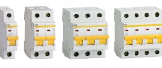
| Circuit breaker testing | 1-pole circuit breaker | |
| 3-pole circuit breaker: | 90 rub. | |
| up to 50 A | 230 rub. | |
| up to 200 A | 360 rub. | |
| up to 1000 A | 430 rub. | |
| > 1000 A | ||
| Calculate the service online | Calculator | |
Loading of machines is carried out by devices, the circuit of which includes:
- LATR – laboratory transformers.
- KU – control keys.
- NT – load transformers.
- Shunt ammeters with different measurement limits.
- CT – current transformers.
- Wires.
Employees of the electrical laboratory "EnergoServiceGarant" are highly qualified and have undergone appropriate training, which allows them to load switches in accordance with the requirements of the PUE. Testing devices are selected by technicians based on the type of electrical installation and the required rated current.
Testing procedure for switches
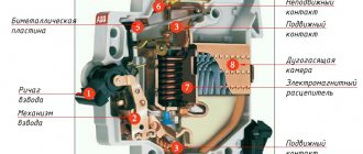
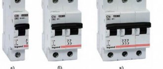
A circuit breaker (circuit breaker) is a device that is installed to protect an electrical circuit from short circuits. This means that the installation of these devices must be carried out exclusively in accordance with the developed project. It is mandatory to test the machines for compliance with the nominal data upon completion of installation operations. During the verification process, the following indicators are identified:
- Rated current.
- Protection trip current.
- Protection response time.
The indicators obtained after checking in accordance with the PUE of circuit breakers are entered into a protocol, which has an approved form.
When should machines be loaded?
To prevent the possibility of a short circuit or overload in the network, it is necessary to load the circuit breakers in the following cases:
- After completion of electrical installation work.
- To assess the condition of equipment after commissioning.
- When there is a suspicion of equipment malfunction.
- After inspection of contacts or emergency situations (especially if a large current has passed through the switch).
- In order to correctly configure the performance of the machines.
Manufacturers indicate the frequency of testing in the passport of each specific type of device.
Set "Sinus-3600"
Designed for loading circuit breakers with test current up to 3600A. It allows loading of circuit breakers, both new/dismantled and as part of an installed electrical installation. When conducting tests, the equipment under test must be de-energized.
Main features of the Sinus-3600 kit:
- testing the electromagnetic release of circuit breakers;
- testing of thermal release of circuit breakers;
- testing of semiconductor circuit breakers.
- testing of circuit breakers disconnected from the electrical installation does not create risks for other elements of the installation and equipment;
- small measurement error;
- test current is close to sinusoidal.
- it is impossible to check short-circuit protection for releases with a setting greater than 3600A;
- inconvenience of transportation (the center of gravity is greatly shifted back) and heavy weight
22 kg;
- inconvenient interface and unclear instruction manual.
Cost of loading circuit breakers in Moscow
Installation of electrical installations requires acceptance and delivery work, which will allow it to be put into operation and used for its intended purpose. When planning to install circuit breakers, you should turn to professionals who can install circuit breakers at a reasonable price in a short time. The electrical laboratory "EnergoServiceGarant" is ready to offer you the services of specialized specialists who will carry out all the necessary tests in Moscow in accordance with regulatory technical documentation. After completing the work, we will provide the client with an inspection report, based on which you can safely use electrical equipment and prevent short circuits or overloading of the electrical network in the future. To order services, fill out the form or request a call back on the website.
Operating procedure:
The operator installs the AV into the test slots, connects the circuits, and closes the upper compartment of the cabinet.
On the PC screen, the operator selects the type of AB, testing mode (types and number of cycles, etc.), enters the batch number, and presses the “Start” button.
The stand supplies the required load current to the circuit breaker, constantly monitoring the state of the circuit breaker. When any circuit breaker is disconnected, the stand shunts it (switching current bypassing the circuit breaker) to continue testing the remaining circuit breakers. In this case, the response time and loading current are recorded.
Current results are displayed on the PC screen.
At the end of testing (when all the circuit breakers are triggered, or at the end of the specified testing time), the stand removes the current supply and displays the results of testing the circuit breakers on the screen for the operator. The operator, if necessary, can print the inspection report.
After this, the testing cycle can be repeated, with these or other parameters.
Device for loading circuit breakers
Loading circuit breakers or any other automatic devices is testing the necessary operating parameters of a technical device, which is accompanied by modeling of the installation circuits.
Such services are carried out by trained specialists working in electrical laboratories, using all necessary equipment.
Our specialists have extensive experience (at least 5 years) and high qualifications. EnergoServiceGarant employees carry out their work using proven methods. Contact us and your devices will be guaranteed to be safe.
UPTR-2MC Device for testing current releases of automatic circuit breakers, current up to 14 kA
Purpose of the UPTR-2MC device:
The UPTR-2MC device is designed to test the characteristics of electromagnetic, thermal and electronic releases of AC and DC circuit breakers (with rated current up to 800 A inclusive) by supplying a certain amount of sinusoidal current with a frequency of 50 Hz (with an output current range of 0 - 14000 A) to the release and measuring the time of its passage.
In addition, the presence in each model of adjustable sources of alternating and direct voltages from 0 to 250 (380) V allows you to check, if necessary, relay equipment, as well as measure the parameters of high-voltage switch drives: voltage and on (off) time.
Each UPTR model can operate in millisecond watch mode, started and (or) stopped by an external contact of various relay devices.
UPTR consist of the following blocks: Regulating and measuring in one housing and load in the other. The control unit contains a voltage regulator (RN), a synchronization circuit for the supply of measuring current (CC) and a measuring complex (SI). The load block contains load (VT) and measuring transformers (CT).
Scope of application of the UPTR-2MC device:
Checking currents and response times of instantaneous, thermal and electronic current releases of AC and DC circuit breakers, as well as relay protections.
Features of UPTR:
- The sinusoidality of the supplied current, which meets the requirements of GOST, allows creating a real short-circuit mode for the releases.
- Possibility of reliable testing of all types of releases: el. magnetic, thermal, electronic.
- Good measurement accuracy.
- The use of a high-speed digital memory ammeter circuit makes it possible to measure the current with a circuit breaker turn-off time of about 1 ms ± 10%.
- Synchronizing the moment of the supplied current with the mains voltage allows you to: a) eliminate the aperiodic component in the current supplied to the instantaneous release. b) obtain the same values of the supplied current at any time of switching on.
- Possibility of using the device to test relay protection by current, time, and test current transformers.
- Possibility of checking drives of high-voltage circuit breakers based on voltage and response (return) time.
- Current is supplied to the machine under test without using the short circuit mode of the supply network.
- Possibility of testing low-amperage circuit breakers (circuit machines with high internal resistance).
- Possibility of checking the operation parameters of relay equipment using alternating and direct voltages with measuring the time characteristics of the equipment.
- Possibility of using the device as a stand-alone millisecond watch (stopwatch), started and stopped by contacts of external devices.
- Wide range of time delay measurements - 999.9 ms; 99.99 sec; 9999 sec
- Relatively low price.
- Relatively light weight and compactness, which allows the load block to be placed directly next to the machine being tested.
Contents of delivery:
- Load block UPTR-2MC
- Adjustment block
- Flexible connectors 95 mm² - 8 pcs.
- Flexible connectors 16mm², length 1.5m - 2 pcs.
- Adapters - 6 pcs.
- Manual
- Verification method
- Dummy connector
Specifications:
| Parameter | Meaning | |
| The strength of the generated currents at the main outputs Ш1-Ш2 (real currents per machine) | 12500 - 13500 A | |
| Reduced relative error in measuring the strength and duration of current under operating conditions, no more | ±5% | |
| Time to establish operating mode, no more | 6 sec | |
| Duration of continuous operation in ready mode | 8 ocloc'k | |
| Maximum duration of the generated current at the main outputs Ш1-Ш2: | Automatic control, with | |
| 1000 | 7200 | 0,2 ( 0,5 ) |
| 2000 | 400 | 0,2 ( 0,5 ) |
| 3000 | 180 | 0,2 ( 0,5 ) |
| 4000 | 50 | 0,2 ( 0,5 ) |
| 10500 | 10 | 0,2 ( 0,5 ) |
| 14000 | — | 0,2 ( 0,5 ) |
Note: The indicated modes are given for the case of heating the transformer of the BN unit to +55°C at an ambient temperature of +25°C.
Stage of “coarse” current regulation (with the number of steps = 6) 12.5 - 14% Stage of fine current regulation (with the number of steps = 12) 1.3 - 1.5% Minimum currents at additional outputs Cl1-Cl2, no more than 5 AMmaximum duration of the generated current at additional outputs Cl1-Cl2:| Automatic control, with | ||
| 8 … 80 | 420 | 0,2 ( 0,5 ) |
| 80 … 100 | 300 | 0,2 ( 0,5 ) |
| 100 … 150 | 120 | 0,2 ( 0,5 ) |
| 150 … 200 | — | 0,2 ( 0,5 ) |
- BR block, no more
- BN block, no more
- BR block
- BN block
- ambient temperature
- relative humidity, (at temperature +25°С), no more
When is it necessary to load circuit breakers?
Monitoring the serviceability of machines is a necessity, according to regulatory requirements. to check circuit breaker loading device in the following situations:
- If the development of the device has been completed and certification has been passed;
- If you have just started using the device;
- If a preventive and scheduled inspection of the device is carried out;
- If various types of repair work have been performed on the device.
Loading devices
To load circuit breakers using primary current, loading devices are usually used. Now there are many such devices that differ in certain characteristics depending on the types and rated currents.
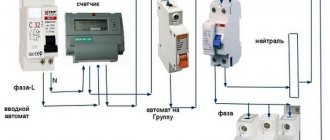
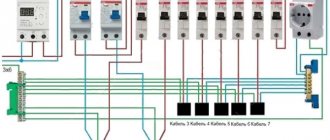
A generalized diagram of a simple loading device includes:
- laboratory autotransformer (LATR)
- control key (KU)
- load transformer (LT)
- ammeter with different measurement limits (shunt)
- current transformer (CT)
- connecting wires
- stopwatch
Device "Saturn-1M"
Designed for testing and adjusting circuit breakers with thermal and electromagnetic releases. A distinctive feature of the Saturn-M device is the ability to load circuit breakers connected directly to the power grid without a load transformer. In electrical installations in operation, this feature allows you to test individual circuit breakers without disconnecting the distribution boards from the power source and thereby without affecting the operation of other consumers. This allows you to minimize downtime of equipment and workplaces and is especially important when carrying out measurements in production with a continuous cycle.
However, this verification method has certain limitations:
Source