Power in an alternating current circuit
Electrical appliances connected to the electrical network operate in an alternating current circuit, so we will consider power under these conditions. However, first, let's give a general definition of the concept.
Power is a physical quantity that reflects the rate of conversion or transmission of electrical energy.
In a narrower sense, they say that electrical power is the ratio of the work performed over a certain period of time to this period of time.
If we rephrase this definition less scientifically, it turns out that power is a certain amount of energy that is consumed by the consumer over a certain period of time. The simplest example is an ordinary incandescent lamp. The rate at which a light bulb converts the electricity it consumes into heat and light is its power. Accordingly, the higher this indicator is initially for a light bulb, the more energy it will consume and the more light it will give off.
Since in this case there is not only a process of converting electricity into some other (light, heat, etc.), but also a process of oscillation of the electric and magnetic field, a phase shift appears between the current and voltage, and this should be taken into account in further calculations.
When calculating power in an alternating current circuit, it is customary to distinguish active, reactive and apparent components.
Concept of active power
Active “useful” power is that part of the power that directly characterizes the process of converting electrical energy into some other energy. It is designated by the Latin letter P and measured in watts (W).
Calculated using the formula: P = U⋅I⋅cosφ,
where U and I are the root mean square value of the voltage and current of the circuit, respectively, cos φ is the cosine of the phase shift angle between voltage and current.
IMPORTANT! The formula described earlier is suitable for calculating circuits with a voltage of 220V, however, powerful units usually use a network with a voltage of 380V. In this case, the expression should be multiplied by the root of three or 1.73
Power triangle and cosine Phi
If you take the entire circuit, analyze its composition, phases of currents and voltages, then construct a vector diagram. After this, draw the active one along the horizontal axis, and the reactive one along the vertical axis and connect the ends of these vectors with the resulting vector - you get a triangle of powers.
It expresses the ratio of active and reactive power, and the vector connecting the ends of the two previous vectors will express the total power. This all sounds too dry and confusing, so look at the picture below:
The letter P denotes active power, Q – reactive power, S – apparent power.
The total power formula is:
The most attentive readers probably noticed the similarity of the formula to the Pythagorean theorem.
- P – W, kW (Watts);
- Q – VAR, kVAr (reactive volt-amperes);
- S – VA (Volt-Amps);
What does this mean
In alternating current networks, which absolutely the whole world uses today, there is no way to do without active and reactive powers - they are interdependent and even necessary. Active electricity refers to the voltage that is generated at thermal power plants, state district power plants, nuclear power plants, a mobile generator standing in a garage, etc. – it goes to the consumer (to factories, factories, to our home) and powers all electrical appliances from a network of ≈220-380 V. At the same time, the function of the reactive component of the total current is to wander aimlessly from the source to the consumer and back. So where does this seemingly useless substance come from?
The thing is that in our homes, businesses and any other electrified objects there are devices with inductive coils (for example, we can take the stator of a motor), where magnetic fields constantly arise. That is, some of them rotate the rotor (armature), and some return back, and so on ad infinitum, as long as there is movement of active energy. This is well demonstrated by a mug of fresh beer: a person drinks only a small part of the foam with the liquid, and leaves the rest in the glass or blows it to the ground. But this very foam is a product of fermentation (induction), without which there will be no beer at all.
Now we can sum up the first conclusion in understanding the topic: if there is an inductive load (and it always exists), then a reactive current will certainly appear, consumed by induction, which itself creates it. That is, induction generates reactive power, then consumes it, generates it again, and so on constantly, but therein lies one problem. To move the reactive substance back and forth, active energy is needed, which is consumed due to the constant movement of electrons along the wires (heating of the wires).
It will be interesting➡ VVGNG cable: design, markings, main characteristics
Can we come to the conclusion that the active power of a generator is the complete opposite of reactive, seemingly useless power? But that's not true. Remember, the sisters are inseparable from each other, because they love each other, and no one will drink beer without foam, and the drink will not be able to ferment without it. The same can be said about reactive power - without it it is impossible to create magnetic fields, so this force will have to be taken into account. But then the brain convolutions of the inventors came into play, who decided to reduce the territorial space (not to drive back and forth along the wires) of this not entirely clear substance and produce it in close proximity to the object of consumption.
For a clear example, you can take the well-known electric hair dryer, which has a motor that rotates a shaft with blades - it is called a turbine for supplying hot air. So, in order to relieve the power line from the useless running of the reagent from the station to the consumer and back, a capacitor of the required capacity is built into the device body. Imagine the same electric welding or turning shop with dozens of powerful machines - what potential is released by reactive current to increase efficiency. In technical terms, the installation of capacitors or other static compensating elements is called reactive power compensation. It turns out that active and reactive power are two inextricably linked quantities.
Generators at power plants of any type can also generate reactive power. To do this, it is enough to change the excitation current (overexcitation, underexcitation) and the generator will be both a supplier and a consumer of this value. But these are just the laws of physics, which in this case are not very beneficial for people, so it is best to transfer the storage and release capacity as close to the source as possible - to the body of the device (unit) or to the production workshop.
Simplified calculation 220/36 V
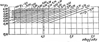
A standard 220/36 V transformer is represented by three main components in the form of a primary and secondary winding, as well as a magnetic circuit. A simplified calculation of a power transformer includes determining the cross-section of the core, the number of winding turns and the diameter of the cable. The initial data for the simplest calculation is represented by the voltage on the primary winding U1 and on the secondary winding - U2, as well as the current on the secondary winding or I2.
As a result of a simplified calculation, a relationship is established between the core cross-section Scm² squared and the total transformer power, measured in W. For example, a device with a core having a cross-section of 6.0 cm² can easily “process” a power of 36 W.
The calculation uses known parameters in the form of power and voltage on the secondary circuit, which makes it possible to calculate the current indicators of the primary circuit. One of the important parameters is efficiency, which does not exceed 0.8 units or 80% for standard transformers.
Do you install electrical equipment yourself? The transformer connection diagram is presented on our website.
Do you suspect that the transformer is faulty? You can read about how to check it with a multimeter here.
Read also: The hydraulic press does not press
You will learn how a transformer differs from an autotransformer in this topic.
Indicators of the total or net power of multi-winding transformers are the sum of the powers on all secondary windings of the device. Knowledge of fairly simple formulas allows you not only to easily calculate the power of the device, but also to independently manufacture a reliable and durable transformer that functions in optimal mode.
How to find out what power is in an AC circuit
It is worth pointing out that this is a value that is directly related to other indicators. For example, it is directly dependent on time, force, speed, vector of force and speed, modulus of force and speed, moment of force and speed of rotation. Often in formulas when calculating electrical power, the number Pi is also used with the resistance indicator, instantaneous current, voltage in a specific section of the electrical network, active, total and reactive power. Direct participants in the calculation are the amplitude, angular velocity and initial current strength with voltage.
Power formula in an alternating current circuit
Types of energy
Below are the main types of loads that are used in everyday life. They can be found in household appliances, as well as in various motors or sensors.
Active
For this work, Ohm's law is used, which is fulfilled every second of time and is similar to the rule for alternating current. This type is used in lamps for lighting or in electric stoves.
You might be interested in what power is the 16a machine designed for?
Active capacitive load formula
Capacitive
This type converts the energy of electric current in an electric field over a certain period of time, and then converts it into electric current. And also, here the current strength will be ahead of the voltage.
An example would be a capacitor. Unfortunately, it is impossible to meet full reactive loads in any device. Each type does not have an efficiency of 100%, because there are energy losses in the air and so on. Therefore, the name active-reactive work is most often used.
Inductive
This type converts energy into a magnetic field, and then changes it into electric current. The current strength in this case will lag behind the voltage. For example, you can take an inductive coil or a throttle sensor on a car.
Functioning of rectifiers
In a single-phase circuit
You can understand what power indicator is in a single-phase alternating current circuit by using a current transformer. To do this, you need to use a wattmeter, which is connected through a current transformer. The readings should be multiplied by the transformer current coefficient. When measuring power at high voltage, a current transformer is needed to insulate the wattmeter and ensure the safety of the user. The parallel circuit is not connected directly, but thanks to a voltage transformer. Secondary windings with housings of measuring transformer installations must be grounded to avoid accidental insulation damage and high voltage contact with devices.
Note! To determine the parameters in the network, it is necessary to multiply the ammeter by the transformer current coefficient, and multiply the numbers obtained by the voltmeter by the transformer voltage coefficient.
In a single-phase circuit
Starting current
When calculating, it is necessary to take into account the starting currents of the device. For example, the resistance of the filament in a light bulb at the moment of switching on is 10 times less than in operating mode. Therefore, the starting current of this light bulb is 10 times greater. After some time, it will begin to consume the power that is recorded in the data of this light bulb. Therefore, when turned on, it burns out due to high inrush currents.
In electronic equipment, until the capacitor in the power supply is charged, an inrush current is also generated.
In electric motors, a starting current is also generated until the engine reaches rated speed.
In heating devices, a starting current is generated until the coil heats up to the standby temperature.
Electrical appliances affecting the quality of consumption
The power factor is equal to unity when connecting lamps and heaters. It decreases to 0.7 or less when electric motors and other components with reactive components, which dominate in energy consumption, are added to the circuit.
The correct application of power definitions and calculations helps optimize the electrical network design taking into account the characteristics of the connected loads. The above information will be useful at the stage of determining the parameters of wiring and circuit breakers. The integrated use of this knowledge will increase the reliability of power supply and prevent the occurrence and development of emergency situations.
How to calculate transformer power
The peculiarity of the operation of a standard transformer is represented by the process of converting alternating current electricity into alternating magnetic field indicators and vice versa. Independent calculation of transformer power can be performed in accordance with the cross-section of the core and depending on the load level.
Calculation of the voltage converter winding and its power
According to the cross section of the core
An electromagnetic device has a core with a pair of wires or several windings. This component of the device is responsible for the active induction increase in the magnetic field level. Among other things, the device promotes the efficient transfer of energy from the primary winding to the secondary winding through a magnetic field that is concentrated in the inner part of the core.
Read also: How to make a lamp for an aquarium with your own hands
The parameters of the core determine the overall transformer power, which exceeds the electrical power.
The calculation formula for this relationship is:
So x Sc = 100 x Pr / (2.22 x Bs x A x F x Ko x Kc), where
- Sо - indicators of the core window area;
- Sc is the cross-sectional area of the core;
- Рг - overall power;
- Bс - magnetic induction inside the core;
- A is the current density in the conductors on the windings;
- F—alternating current frequency indicators;
- Ko is the window fill factor;
- Kc is the core fill factor.
The transformer power indicators are equal to the load level on the secondary winding and the power consumption from the network on the primary winding.
By load
When choosing a transformer, several basic parameters are taken into account, presented:
- category of electrical supply;
- overload capacity;
- scale of standard power of devices;
- load distribution graph.
Currently, the typical transformer power is standardized.
To calculate the power connected to a transformer device, it is necessary to collect and analyze data on all connected consumers. For example, if there is a purely active load represented by incandescent lamps or heating elements, it is sufficient to use transformers with power ratings of 250 kVA.
What is the difference between active power and reactive power – All about electricity
The power characteristics of an installation or network are basic for most known electrical appliances. Active power (transmitted, consumed) characterizes the part of the total power that is transmitted over a certain period of alternating current frequency.
Only alternating current can have active and reactive power, since the network characteristics (current and voltage) of direct current are always equal.
The unit of measurement for active power is Watt, while reactive power is measured by reactive voltampere and kiloVAR (kVAR).
It is worth noting that both full and active characteristics can be measured in kW and kVA, this depends on the parameters of the specific device and network. In industrial circuits it is most often measured in kilowatts.
Energy ratio
Electrical engineering uses the active component to measure the energy transfer of individual electrical devices. Let's look at how much power some of them consume:
| Device | Power of household appliances, W/hour |
| Charger | 2 |
| Fluorescent lamp DRL | From 50 |
| Acoustic system | 30 |
| Electric kettle | 1500 |
| Washing machine | 2500 |
| Semi-automatic inverter | 3500 |
| High pressure washer | 3500 |
Based on everything said above, active power is a positive characteristic of a specific electrical circuit, which is one of the main parameters for selecting electrical appliances and controlling electricity consumption.
Active component generation
Reactive component designation:
This is a nominal value that characterizes the loads in electrical devices using EMF fluctuations and losses during operation of the device. In other words, the transmitted energy goes to a specific reactive converter (this is a capacitor, diode bridge, etc.) and is manifested only if the system includes this component.
To find out the active power indicator, you need to know the total power; the following formula is used to calculate it:
It will be interesting➡ Magnetic induction. Definition and description of the phenomenon
S = UI, where U is the network voltage and I is the network current.
The same calculation is performed when calculating the energy transfer level of the coil with a symmetrical connection. The diagram looks like this:
Symmetrical load diagram
The calculation of active power takes into account the phase angle or coefficient (cos φ), then:
S = U * I * cos φ.
A very important factor is that this electrical quantity can be either positive or negative. It depends on what characteristics cos φ has.
If the phase shift angle of a sinusoidal current is in the range from 0 to 90 degrees, then the active power is positive, if from 0 to -90, then it is negative.
The rule is valid only for synchronous (sinusoidal) current (used to operate an asynchronous motor or machine tool equipment).
Also, one of the characteristic features of this characteristic is that in a three-phase circuit (for example, a transformer or generator), the active indicator is completely generated at the output.
Three-phase network calculation
Maximum and active power is denoted by P, reactive power by Q.
Due to the fact that reactive is determined by the movement and energy of the magnetic field, its formula (taking into account the phase shift angle) has the following form:
QL = ULI = I2xL
For non-sinusoidal current it is very difficult to select standard network parameters. To determine the required characteristics for the purpose of calculating active and reactive power, various measuring devices are used. This is a voltmeter, ammeter and others. Based on the load level, the desired formula is selected.
Due to the fact that the reactive and active characteristics are related to the total power, their relationship (balance) is as follows:
S = √P2 + Q2, and all this equals U*I.
But if the current passes directly through the reactance. There are no losses in the network. This is determined by the inductive inductive component - C and resistance - L. These indicators are calculated using the formulas:
Inductance resistance: xL = ωL = 2πfL,
Capacitance resistance: xc = 1/(ωC) = 1/(2πfC).
To determine the ratio of active and reactive power, a special coefficient is used. This is a very important parameter by which you can determine what part of the energy is used for other purposes or is “lost” during operation of the device.
If there is an active reactive component in the network, the power factor must be calculated.
This quantity has no units of measurement; it characterizes a specific current consumer if the electrical system contains reactive elements.
Using this indicator, it becomes clear in which direction and how the energy shifts relative to the network voltage. To do this you will need a voltage triangle diagram:
Stress Triangle Diagram
For example, if there is a capacitor, the coefficient formula is as follows:
cos φ = r/z = P/S
To obtain the most accurate results, it is recommended not to round the data obtained.
Considering that when the currents resonate, the reactive power is 0:
Q = QL – QC = ULI – UCI
In order to improve the quality of operation of a particular device, special devices are used to minimize the impact of losses on the network. In particular, this is a UPS. This device does not require electrical consumers with a built-in battery (for example, laptops or portable devices), but for most others an uninterruptible power supply is necessary.
When installing such a source, you can not only determine the negative consequences of losses, but also reduce the cost of paying for electricity. Experts have proven that on average, a UPS will help save from 20% to 50%. Why is this happening:
- The load on power transformers is significantly reduced;
- The wires heat up less, this not only has a positive effect on their operation, but also increases safety;
- Signaling and radio devices have reduced interference;
- Harmonics in the electrical network are reduced by an order of magnitude.
Capacity Triangle
To understand the reactive load, consider the power triangle.
where P is active power, which is measured in Watts and is used to perform useful work;
Q – reactive, which is measured in Vars and is used to create an electromagnetic field;
S – total power is used to calculate electrical circuits.
To calculate the total power, we use the Pythagorean theorem: S 2 =P 2 +Q 2. Or using the formula: S=U*I, where U is the voltage reading across the load, I is the reading of the ammeter, which is connected in series with the load. The calculations also use the power factor - cosφ. On devices that relate to reactive loads, active power and cosφ are usually indicated. Using these parameters you can also get full power.
Sometimes devices indicate total power, but cosφ is not indicated. In this case, a coefficient of 0.7 is applied.
What is phase angle
Nikola Tesla saw the world as an ether filled with vibrations of different frequencies. Matter is formed from harmonics. Tesla prophesied, for example:
- The emergence of the Internet.
- Central news releases on radio and television.
- Coverage of the planet by energy networks.
Today the world around us seems simple. Tesla foresaw the world a hundred years later. In physics and radio engineering, it is convenient to represent an oscillation in the form of a vector (directed segment) rotating around the origin of coordinates at a speed equal to its natural frequency. The circular frequency is found as ω = 2 Pi f. The parameter is used in a number of formulas.
When the current source generates power, the current and voltage rotate synchronously with zero phase shift. Of course, reality is very different from the ideal, but what is happening is understandable. For the voltage of the secondary winding of the transformer the following expression is written:
E2 = I2R2 + U2 + I2 2 Pi L, where:
- I2 – secondary winding current, slightly behind the voltage, but not by 90 degrees;
- U2 – output voltage on the winding, together with I2 it is supplied to enterprises and other consumers;
- I2R2 – heat loss through the ohmic resistance of the secondary winding (found according to Ohm’s law);
- I2 2 Pi L - the reactive component of the voltage, as can be seen from the figure, is deposited perpendicular to the current, causing a phase shift.
So, inductive reactance leads to the fact that low-quality energy is shipped to consumers. To rectify the situation, capacitor blocks are installed at substations. Then the reactive resistances will balance each other, and the reactive power will begin to circulate only throughout the substation territory. This is bad, but this is the principle of electromagnetic induction. The supplier will ship clean active power to consumers without phase shifts.
As mentioned above, enterprises will consume some of the power, but parasitic effects are inevitable. It's time to remember the definition given at the beginning. Some sources claim that active power is converted into other types of energy. When the compensating installation gains reactive power, it then releases it to the inductance not indefinitely. Reactive power is dissipated gradually in the form of heat on the cables. It is incorrect to talk about certain transformations. Let's summarize:
- In industry, reactive power refers to the energy sent back through a power circuit. The effect from start to finish today is negative.
- In physics, reactive power appears immediately when a phase shift occurs. Not always a parasitic effect.
The two definitions are closely related and inseparably present in the literature. It remains to add that compensating installations do not always need to be installed at substations. The resistance of power lines has a pronounced capacitive tint. The negative effect is balanced by skillful design. There is sometimes a need to install reactors in order to avoid a number of negative aspects.
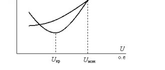
Overloads of power transformers
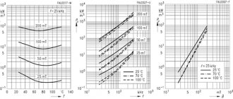
Overloads are determined by converting a given load curve into a thermally equivalent one (Fig. 3.5). The permissible load of the transformer depends on the initial load, the maximum load and its duration and is characterized by the load excess factor:
Permissible systematic overloads of transformers are determined from graphs of the load capacity of transformers, specified in tables or graphically. The overload factor is transmitted depending on the average annual air temperature/sp type of cooling and transformer power, the initial load factor kn n and the duration of the two-hour equivalent maximum load tmax.
For other values of tmax, the permissible value can be determined from the load capacity curves of the transformer.
If the maximum load schedule in summer is less than the rated power of the transformer, then in winter a long-term 1% overload of the transformer is allowed for each percentage of underload in summer, but not more than 15% . The total systematic overload of the transformer should not exceed 150%. In the absence of systematic overloads, long-term loading of transformers with a current 5% higher than the rated current is allowed, provided that the voltage of each winding does not exceed the rated one.
On transformers, it is allowed to increase the voltage above the rated one: for a long time - by 5% at a load not higher than the rated one and by 10% at a load not higher than 0.25 rated; short-term (up to 6 hours per day) - by 10% at a load not higher than the nominal one.
Additional overloads of one branch due to prolonged underload of the other are allowed in accordance with the instructions of the manufacturer. Thus, three-phase transformers with a split winding of 110 kV with a power of 20, 40 and 63 MVA allow the following relative loads: with a load of one branch of the winding 1.2; 1.07; 1.05 and 1.03 loads of the other branch should be 0, respectively; 0.7; 0.8 and 0.9.
Read also: Schematic designation of sockets and switches