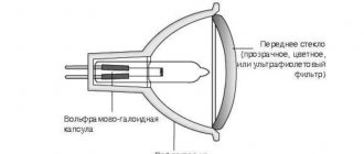
Halogen lamps can be considered an improved version of the usual incandescent lamps. They work the same way, but due to some features of halogens they are more economical, durable and produce a light that is pleasant to the eye, but at the same time bright.
Manufacturers offer two options for halogen lighting devices: high- and low-voltage. For the latter to work correctly, a transformer for halogen lamps is required. We will tell you how to select and correctly connect the specified device.
Why does a halogen need a transformer?
Halogen lamps successfully compete with LEDs. Despite the best performance characteristics of the latter, it is often halogens that win, which is explained by their lower cost and, accordingly, availability, as well as some features of the light beam of LEDs, which can tire the eyes.
The main “trump card” of LEDs is operation without heating, which makes it possible to widely use them. Halogen lamps have the same advantage, but only for low-voltage lamps. They can be installed in areas sensitive to high temperatures. For example, in lamps built into the ceiling.
But you need to understand that low-voltage halogen lamps can only work with transformers. The latter are necessary to convert the mains voltage to an acceptable value for the lamp. Usually this is 12 V.
In addition, the transformer protects the light source from power surges, overheating and short circuits, and can also provide the ability to smoothly turn on the lighting. It must be admitted that, on average, lamps with transformers last much longer. Although a lot depends on their quality.
Low-voltage halogen lamps are not capable of operating from a mains voltage of 220 V, so they must be connected only through a step-down transformer
How to choose the right one
When choosing a step-down transformer, two main parameters are taken into account: output voltage and rated power. The first must clearly correspond to the operating voltage of the connected halogens (12v). The second characteristic is the sum of the power indicators of the sources associated with the transformer, plus the reserve for the correct functioning of the unit (15-20%).
The second feature is related to the dimensions of the selected device and its installation location. The more powerful the equipment, the larger the dimensions.
If there are several light elements, it is advisable to distribute them into groups with separate transformers.
What types of transformers are there?
Transformers are devices of electromagnetic or electronic type. They differ somewhat in the principle of operation and some other characteristics.
Electromagnetic options change the parameters of the standard mains voltage to characteristics suitable for operation of low-voltage halogen lamps; in addition to the specified work, electronic devices also perform current conversion.
Toroidal electromagnetic device
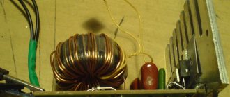
The simplest toroidal transformer is assembled from two windings and a core. The latter is also called a magnetic circuit. It is made from a ferromagnetic material, usually steel. The windings are placed on the rod.
The primary is connected to the energy source, the secondary, respectively, to the consumer. There is no electrical connection between the secondary and primary windings.
Despite its low cost and operational reliability, a toroidal electromagnetic transformer is rarely used today when connecting halogen lamps
Thus, power is transferred between them only electromagnetically. To increase the inductive coupling between the windings, a magnetic circuit is used. When alternating current is applied to the terminal connected to the first winding, it produces an alternating type of magnetic flux inside the core.
The latter meshes with both windings and induces an electromotive force or emf in them. Under its influence, an alternating current with a voltage different from what was in the primary winding is created in the secondary winding.
Depending on the number of turns, the type of transformer is determined, which can be step-up or step-down, and the transformation ratio. For halogen lamps, only step-down devices are always used.
The advantages of winding devices are:
- High operational reliability.
- Easy to connect.
- Low cost.
However, toroidal transformers can be found quite rarely in modern circuits with halogen lamps. This is explained by the fact that, due to their design features, such devices have quite impressive dimensions and weight. Therefore, it is difficult to disguise them when arranging furniture or ceiling lighting, for example.
Perhaps the main disadvantage of toroidal electromagnetic transformers is their massiveness and significant dimensions. They are extremely difficult to disguise if a hidden installation is necessary
Also, the disadvantages of devices of this type include heating during operation and sensitivity to possible voltage drops in the network, which negatively affects the service life of halogen lamps.
In addition, winding transformers may hum during operation; this is not always acceptable. Therefore, the devices are used mostly in non-residential premises or in industrial buildings.
Pulse or electronic device
The transformer consists of a magnetic core or core and two windings. Depending on the shape of the core and the method of placing windings on it, four types of such devices are distinguished: rod, toroidal, armored and armored.
The number of turns of the secondary and primary winding may also be different. By varying their ratios, step-down and step-up devices are obtained.
The design of a pulse transformer contains not only windings with a core, but also electronic filling. Thanks to this, it is possible to integrate protection systems against overheating, soft start and others.
The operating principle of a pulse type transformer is somewhat different. Short unipolar pulses are applied to the primary winding, due to which the core is constantly in a state of magnetization.
Pulses on the primary winding are characterized as short-term rectangular signals. They generate inductance with the same characteristic drops.
They in turn create pulses on the secondary coil.
This feature gives electronic transformers a number of advantages:
- Light weight and compact.
- High level of efficiency.
- Possibility to build in additional protection.
- Extended operating voltage range.
- No heating or noise during operation.
- Possibility of adjusting the output voltage.
Among the disadvantages, it is worth noting the regulated minimum load and the rather high price. The latter is associated with certain difficulties in the manufacturing process of such devices.
Classification and principle of operation
Step-down equipment for halogen lighting elements exists in two versions:
- electromagnetic;
- electronic.
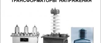
The first of these transformers is also called toroidal due to the design features: the basis of the primary and secondary windings is a toroid-shaped core. The operating principle of this option is based on the electromagnetic connection of two coils. A voltage of 220 volts is supplied to the input; as a result of the conversion, the transformer for halogen lamps produces a reduced voltage of 12 volts.
This option has been on the market for a long time, and is still used due to its reliability and reasonable cost. The weight of the toroidal transformer alone is about 3.5 kg, which significantly complicates the task of arranging a lighting system using built-in halogen lamps. Another disadvantage is the high sensitivity to sudden voltage surges.
The electronic (also known as pulse) analogue is in many ways superior to the device discussed above. Its advantages:
- output voltage stability (6V, 12V, 24V);
- high power factor;
- protection against voltage surges;
- smooth start;
- small device sizes.
All these properties allow the electronic analogue to be used much longer. The power supply/driver operates on a similar principle for LED lamps. The electronic transformer has a simple design; it is based on a push-pull self-generator.
All elements are placed in a housing; two terminals are provided for connection to a 220 volt power source, and the same number are provided for connection to a halogen lamp (voltage 12 volts).
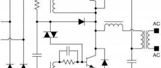
The electronic transformer circuit looks like this:
An electronic transformer contains a ferrite core, transistors (half-bridge circuit), and diodes. The design of this design option is somewhat more complicated, but the result is a stable voltage of 12 volts and a longer service life of the light source.
Rules for choosing step-down equipment
When choosing a transformer for halogen light sources, you need to take into account many factors. It’s worth starting with two important characteristics: the output voltage of the device and its rated power.
The first must strictly correspond to the operating voltage of the lamps connected to the device. The second determines the total power of the light sources with which the transformer will work.
There is always a marking on the transformer body, by studying which you can obtain complete information about the device
To accurately determine the required rated power, it is advisable to make a simple calculation. To do this, you need to add up the powers of all light sources that will be connected to the step-down device. To the resulting value, add 20% of the “reserve” necessary for the correct operation of the device.
Let's illustrate with a specific example. To illuminate the living room, it is planned to install three groups of halogen lamps: seven pieces in each. These are point devices with a voltage of 12 V and a power of 30 W. Three transformers will be required for each group. Let's choose the right one. Let's start by calculating the rated power.
Let's calculate and find that the total power of the group is 210 W. Taking into account the required headroom, we get 241 W. Thus, for each group you will need a transformer, the output voltage of which is 12 V, the rated power of the device is 240 W.
Both electromagnetic and pulsed devices fit these characteristics. When choosing the latter, you need to pay special attention to the rated power. It must be presented as two numbers. The first indicates the minimum operating power.
You need to know that the total power of the lamps must be greater than this value, otherwise the device will not work. And a small note from experts regarding the choice of power. They warn that the power of the transformer, which is indicated in the technical documentation, is the maximum.
That is, in normal condition it will produce somewhere around 25-30% less. Therefore, the so-called “reserve” of power is necessary. Because if you force the device to work at its limit, it will not last long.
For long-term operation of halogen lamps, it is very important to correctly select the power of the step-down transformer. At the same time, it must have some “reserve” so that the device does not operate at the limit of its capabilities.
Another important nuance concerns the size of the selected transformer and its location. The more powerful the device, the more massive it is. This is especially true for electromagnetic units. It is advisable to immediately find a suitable place for its installation.
If there are several lamps, users often prefer to divide them into groups and install a separate transformer for each. This is explained very simply.
Firstly, if the step-down device fails, the remaining lighting groups will work normally. Secondly, each of the transformers installed in such groups will have less power than the common one that would need to be installed for all lamps. Consequently, its cost will be noticeably lower.
Connecting a step-down block
In terms of installation method, halogen bulbs are similar to some versions of LED analogues, also designed for a voltage of 12 volts: a transformer with the corresponding contacts is connected to a 220 volt power source, one of the terminals is connected to a switch; on the other side of the device a connection is made to a lamp (12 volts).
The diagram will look like this:
The connection must be made taking into account a number of rules:
- you cannot touch the bulb of the light source, which will lead to burnout, so the entire operation must be performed with gloves that do not leave fibers, or with a napkin;
- if the circuit includes a transformer, dimming devices should not be used;
- in the case when the connection is made using an unreasonably long cable, the intensity of the light flux may be noticeably lower, since the electrical impulse is lost.
These rules make it possible to extend the life of the lamp. For comparison, when installing LED analogues (220 or 12 volts), the requirements are not so stringent due to differences in design.
Two transformer connection options
Before connecting a step-down device, you should complete the layout of the lamps if there are more than two of them. In addition, you need to select the location for installing the transformer.
The latter is done taking into account the following rules:
- Free access to the device must be ensured, which is necessary for its maintenance or replacement.
- If the transformer is located inside a closed space, the volume of the latter cannot be less than 10 liters. This is necessary to remove the heat generated during operation of the device.
- The distance from the device to the nearest halogen lamp should not be less than 250 mm. This is done to avoid unwanted additional heating of the light source.
Only after the location for the transformer and lamps has been determined can installation and connection begin.
The correct choice of location for installing the step-down transformer is important. If it is installed in a confined space, the volume of the latter must be sufficient to remove the heat generated during operation of the device
In this case, two main options are possible, and the latter can be modified and used to connect not only two groups of lamps, but also three or more.
Circuit of lamps with one transformer
This option is considered optimal for four, maximum five light sources. If there are more lamps, it would be best to divide them into groups. Halogens are connected only in parallel. This must be taken into account when drawing up the diagram. Another important point.
It is necessary to place the lamps so that the distance from each of them to the transformer is approximately the same. This is necessary for the correct operation of the devices.
If there are wires of different lengths, the lamps will light differently. The one with a shorter wire will shine brighter. A device with a long cable will light dimly.
In addition, in the latter case, the wire may also heat up during operation, which is extremely undesirable. Experts recommend building the circuit so that the length of each of the wires leading to the lamps does not exceed 200 mm. In this case, the cable cross-section must be at least 1.5 square meters. mm.
A small number of lamps are connected in this way. It is optimal to connect no more than five, otherwise you will have to install a high-power transformer
On the transformer body there are output and input terminals. The primary ones are labeled N and L or Input. This is an input located on the 220 V side. It must be remembered that the connection here is made through a single-key switch.
Next, the neutral and phase wires of blue and orange or brown extending from the distribution box are connected to the corresponding terminals of the transformer. Halogen lamps are connected to the secondary Output terminals or the output of the step-down device.
For this, only copper wires with the same cross-section are used. Important note. If for some reason there are not enough transformer terminals, additional terminal clamps should be installed. They can be purchased at any specialty store.
Two groups of lamps with two transformers
This connection is optimal if there are more than five lamps. Groups can consist of the same number of lamps or different ones. It doesn't matter. The main thing is that the transformer is selected correctly for each. As in the option described above, you should start by executing the diagram.
When choosing a location for lamps, similar rules apply. That is, the length of all wires extending to them from the transformer should be approximately the same.
This is how two groups of halogen lamps are connected. Each of them uses its own transformer, but the switch is common to both
This can be quite difficult to do. Then you will need to make some adjustments. You need to know that for copper wires with a cross-section of 1.5 square meters. mm, which is what is recommended to be used in this case, the optimal length varies from 150 to 300 cm. Over such a distance, energy will be transmitted with minimal losses and without interference.
Sometimes this length is clearly not enough. In this case, you will need to choose a wire with a larger cross-section. For a distance from 300 to 400 cm, a cable with a cross-section of up to 2.5 square meters is selected. mm. If an even greater length is expected, which is undesirable, a special calculation should be carried out and the appropriate cross-section determined using a special table.
Connecting each of the transformers and groups of lamps to it is carried out similarly to the method described above. That is, the neutral core from the distribution box is connected to the neutral terminals of the transformers.
The phase conductor from the switch is connected to the phase cables of the step-down devices. Theoretically, more than two groups of lamps can be connected in this way, but each of them has its own transformer.
Important note. A separate cable is laid for each of the step-down devices, and they are connected exclusively inside the junction box. Some “craftsmen” prefer to connect the wires somewhere under the ceiling, but not use the junction box.
This is a serious mistake that contradicts the PUE, which states that free access must be provided to each of the cable connection sections for inspection, maintenance and possible repairs. Therefore, the only correct option is a connection in a junction box.
In the process of creating halogen lighting with a large number of lamps, it is important to correctly calculate the number of lighting groups and the location of transformers for each of them
Experts emphasize that if you intend to connect a group consisting of a large number of lamps, it is possible to place a distribution box between the lamps and the transformer output. This is especially true if there are not enough terminals on the step-down device or if there are restrictions on its placement.
When choosing this option, you need to know that with the same power, a low-voltage circuit passes more current than a high-voltage circuit. Based on this, an accurate calculation is required to determine the wire cross-section. This is done by calculating the total current.
Let's illustrate with an example. Seven 12V 35W light sources must be connected via a transformer. The lamps are mounted parallel to the distribution box. You need to find out the cross-section of the wire that will be laid between the distributor and the output of the block.
To do this, first multiply the number of light bulbs by their power. Then we divide the resulting value by the operating voltage. We get approximately 29 A. This is the current strength that will pass through the low-voltage wiring.
Using the table of the dependence of the wiring cross-section on the operating voltage presented in the PUE, we determine the appropriate wire size. In our case it will be at least 4 square meters. mm. As you can see, the load is quite large. Perhaps it makes sense to divide this group of lamps into two more.
If you install a two-key switch when connecting two groups of halogen lamps, you can control each of them separately
When installing two groups of halogen light bulbs through a transformer, two types of switches can be used. If you install a single-key model, then both groups can only be turned on/off at the same time. If separate control of groups of lighting devices is required, you can install a two-key switch.
Do-it-yourself power supply modification
To operate halogen lamps, pulsed current sources with high-frequency voltage conversion began to be used. During home production and setup, expensive transistors quite often burn out. Since the supply voltage in the primary circuits reaches 300 volts, very high requirements are placed on insulation. All these difficulties can be completely avoided by using a ready-made electronic transformer. It is used to power 12-volt halogen backlights (in stores), which are powered from a standard electrical outlet.
There is a certain opinion that getting a homemade switching power supply is a simple matter. You can only add a rectifier bridge, a smoothing capacitor and a voltage stabilizer. In reality, everything is much more complicated. If you connect an LED to the rectifier, then only one ignition can be detected when turned on. If you turn the converter off and on again, another flash will occur. In order for a constant glow to appear, it is necessary to connect an additional load to the rectifier, which, taking away useful power, would convert it into heat.
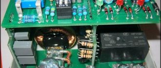
One of the options for self-manufacturing a switching power supply
The described power supply can be made from an electronic transformer with a power of 105 W. In practice, this transformer resembles a compact pulse voltage converter. For assembly, you will additionally need a matching transformer T1, a mains filter, a rectifier bridge VD1-VD4, and an output choke L2.
Bipolar power supply circuit
Such a device operates stably for a long time with a low-frequency amplifier with a power of 2x20 watts. At 220 V and a current of 0.1 A, the output voltage will be 25 V; when the current increases to 2 amperes, the voltage drops to 20 volts, which is considered normal operation.
The current, bypassing the switch and fuses FU1 and FU2, goes to a filter that protects the circuit from interference from the pulse converter. The middle of capacitors C1 and C2 is connected to the shielding casing of the power supply. Then the current is supplied to input U1, from where a reduced voltage is supplied from the output terminals to the matching transformer T1. The alternating voltage from the other (secondary winding) rectifies the diode bridge and smoothes the L2C4C5 filter.
Self-assembly
Transformer T1 is manufactured independently. The number of turns on the secondary winding affects the output voltage. The transformer itself is made on a K30x18x7 ring magnetic core made of M2000NM ferrite. The primary winding consists of a PEV-2 wire with a diameter of 0.8 mm, folded in half. The secondary winding consists of 22 turns of PEV-2 wire, folded in half. By connecting the end of the first half-winding to the beginning of the second, we obtain the midpoint of the secondary winding. We also make the throttle ourselves. It is wound on the same ferrite ring, both windings contain 20 turns.
Rectifier diodes are located on a radiator with an area of at least 50 sq.cm. Please note that diodes whose anodes are connected to the negative output are insulated from the heat sink with mica spacers.
Smoothing capacitors C4 and C5 consist of three K50-46 connected in parallel with a capacity of 2200 μF each. This method is used to reduce the overall inductance of electrolytic capacitors.
It would be better to install a surge filter at the input of the power supply, but it is possible to work without it. For a line filter choke, you can use a DF of 50 Hz.
All parts of the power supply are mounted on a board made of insulating material. The resulting structure is placed in a shielding casing made of thin sheet brass or tinned sheet. Don't forget to drill holes in it for air ventilation.
A correctly assembled power supply does not require adjustment and starts working immediately. But just in case, you can check its performance by connecting a resistor with a resistance of 240 Ohms and a dissipation power of 3 W to the output.
Recommendations from practitioners
Practicing electricians are often faced with the need to install low-voltage halogens when the wiring has already been installed and is being successfully operated. In this case, it is not always possible to parallel connect lamps to a transformer without radically altering the wiring.
To minimize costs, experts recommend in this case connecting each lamp with its own transformer. As a rule, these will be devices that are small in power and size.
If this seems wasteful, you can put high-voltage 220 V halogen lamps instead of low-voltage lamps. But in this case, you will have to equip them with a soft start device. Or, as an option, if the design of the lamp allows, you can replace halogen lamps with economy class LEDs.
The article, which thoroughly examines all aspects of the issue, will introduce you to guidelines for choosing halogens for installing a lighting system.
The ability to adjust the lighting intensity attracts many. Most electronic transformers are equipped with the ability to reduce the input voltage, which allows you to adjust the brightness of halogen lighting
Very often it is planned to regulate the lighting intensity, for which a dimmer is added to the overall circuit. You need to know that most pulse transformers are not designed to work together with a dimmer.
Since the latter negatively affects the functioning of the electronic converter, this ultimately significantly reduces the service life of the connected halogen lamps.
For this reason, the best option for working in conjunction with a dimmer is a toroidal electromagnetic transformer. And one more note.
Electricians strongly recommend not to forget about servicing already installed step-down devices. It is optimal to carry out a routine inspection of them every six months to check their functionality. If problems are identified, the devices are repaired or replaced.
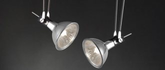
12 V spotlights
The connection diagrams for twelve-volt spotlights are almost identical, except that a step-down transformer (voltage converter) is installed in front of the fixtures, which is powered by a 220 V network.
With 12V transformer
It is permissible to connect N number of lamps to each transformer (voltage converter), which must be taken into account when implementing various connection schemes. It is better not to go beyond what is permitted and not to overload these devices, but on the contrary, connect them with a reserve, without increasing the load.
Connection diagram for spotlights to a two-key switch
If you study these circuits in more detail, they differ only in the presence or absence of hardware such as a step-down transformer or voltage converter.
Transformers and voltage converters
We can safely say that transformers in control circuits or voltage converters are the main electrical devices, without which 12 V spotlights will not work. It is very important that the power of these devices is 20 percent greater than the load power. Calculations are made quite simply: for this, the powers of all the light bulbs that are planned to be connected via a transformer or converter are added up. For example, you need to connect 8 light bulbs (spotlights) with a power of 30 watts each. By multiplying, the total power is determined - 240 watts, plus another 20 percent of the reserve, for a total of about 300 watts. This reserve is quite sufficient for long-term and reliable operation of the circuit.
With converter on each branch
It should be said right away that you should not get carried away with installing powerful transformers or voltage converters, since their dimensions complicate the installation process. In addition, their cost may be prohibitive. It is better to divide the lighting into groups, installing equipment of lower power and smaller dimensions.
You can see how spotlights are mounted in the following video.
Correct and incorrect installation of spotlights
Installation features
Connecting spotlights is a process that includes not only a correctly selected switching circuit, but also a number of technological stages that are directly dependent on the conditions of their installation.
Spotlights in suspended ceilings
Quite often, suspended ceilings are installed using lighting based on spotlights. Before the process of installing the ceiling, it is necessary to carry out all the preparatory work in advance, which also includes the installation of the lamps themselves. In other words, it is necessary not only to connect the lamps, but also to test all the lighting in action.
Prepared for installation of suspended ceilings
Installation of such ceilings is carried out when the circuit is turned off, and the lighting lamps are removed, as well as parts that are susceptible to high temperatures. As a rule, suspended ceilings are installed by specialists, who also cut all the necessary holes in the ceiling and also install additional elements.
Spotlights in plasterboard systems
Recently, plasterboard systems are quite often used for leveling ceilings, as well as for installing ceilings during construction from scratch. The peculiarity of plasterboard systems lies in their high performance characteristics and maintainability, which cannot be said, for example, about stretch ceilings. The technology for installing spotlights is somewhat different, although before installing drywall, the wiring must be routed and tested for functionality, so that you don’t have to look for “ends.” The main task is to determine the places where holes will be cut in the drywall for the lamps. After cutting out the holes, the ends of the wires are found, after which these ends are pulled out. Another important point is that you should always think about additional centimeters of wire, since their excess can always be hidden under the ceiling, and a deficiency is always a problem.
If you need to install a converter
In the case of drywall, it is possible that the wires are separated after installation of the drywall. It is better to do this before puttying the ceiling and generally before finishing work. Unfortunately, this approach is possible if the lamps are located at a short distance from each other. Problems with wiring may arise if the ceiling is wooden and wiring must be carried out in accordance with all fire safety rules. For this, special non-flammable materials are used, preferably metal.