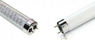
Principle of operation
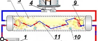
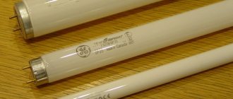
In its classic form, a FL (fluorescent lamp) is a glass tube with a phosphor applied to its inner surface. An inert gas mixed with mercury vapor is placed inside the tube at reduced pressure. Tungsten electrodes (cathodes) are soldered into the ends of the product.
The principle of operation and structure of a fluorescent lamp
In operating condition, after a high voltage breakdown of the gas, a current flows through the lamp, resulting in UV radiation invisible to the human eye. Under the influence of this radiation, the phosphor generates a luminous flux in the visible range, the color shades of which can vary depending on the type of phosphor.
The current during a gas discharge changes like an avalanche and a series-connected load is used to limit it.
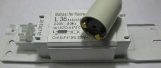
Note! To start and maintain the operating mode of the LL, special ballasts (ballasts) are used. Such equipment is often called ballast.
Starter device for fluorescent lamps
The design of this element is quite simple. Each model produced by a specific manufacturer has its own technical characteristics. This should be taken into account when choosing lamps. The starter is a glass cylinder containing an inert gas. It can be a mixture of helium and hydrogen or neon. Fixed metal electrodes are soldered into the cylinder. Their conclusions pass through the sockets.
The cylinder is located inside a plastic or metal case with a hole on top. The most popular material for making the case is plastic. A special impregnation allows such a housing to cope with high temperatures. Either one has only two legs (contacts).
If you remove the structure from the body, you can see the flask itself. You can also see that some element is connected parallel to the electrodes of the flask - this is a capacitor. Its capacity is about 0.003-0.1 microfarads. The capacitor is designed to perform two functions at once:
- - fights radio interference that occurs due to contact of electrodes by reducing their level.
- - participates in the process of lighting the lamp.
The capacitor reduces the voltage pulse that is formed when the electrodes open and increases its duration.
Due to parallel connection with the electrodes, the capacitor reduces the likelihood of their welding (sticking). A similar phenomenon can occur during the process of opening the electrodes due to the formation of an electric arc. The capacitor extinguishes the arc in the shortest possible time.
Electromagnetic type ballasts
The electrical circuit for powering a LL using conventional ballasts is shown in Fig. 1.
Fig.1. Electrical circuit for powering a LL using conventional ballasts
A starter is a device designed for short-term automatic switching on and off of an electrical circuit.
There are various designs of starters - glow discharge, thermal, electronic, electromagnetic. The most common are glow discharge starters, which use bimetallic plates.
Fig.2. Starter for starting fluorescent lamps
When a glow discharge occurs in the starter, such plates heat up and close the circuit. After the circuit is closed, the discharge stops, the electrodes cool down and open. The starter parameters are selected in such a way that the glow discharge voltage is higher than the operating voltage of the LL and lower than the minimum mains voltage.
Prices for starters for fluorescent lamps
Prices for starters for fluorescent lamps
The inductor is a regular inductor wound around a core. To prevent the appearance of eddy currents in the core, it is assembled from separate thin plates. The permissible power of the throttle must correspond to the power of the LL. Otherwise the lamp will not turn on.
Fig.3. Choke for fluorescent lamps
When the starter short-circuits, a large current passes through the LL electrodes, heating the filaments of these electrodes. and causing thermionic emission. As a result of this emission, electron clouds are formed near the electrodes, facilitating breakdown and the appearance of a discharge.
When the starter contacts open, according to the phenomenon of self-induction, a powerful voltage pulse is generated in the circuit, the magnitude of which is proportional to the inductance of the inductor. Under the influence of this pulse, gas breakdown occurs and a glow discharge occurs, which can turn into an arc. But the presence of a balanced resistance in the form of a choke limits the amount of current flowing through the device.
Thus, the throttle plays a dual role:
- The high-voltage voltage pulse generated by the choke when the starter opens the electrical circuit ensures gas breakdown and ignition of the lamp.
- In the LL combustion mode, the inductive reactance of the choke ensures that the operating voltage is maintained at the lamp electrodes, providing a glow discharge.
In Fig. 1, the compensating capacitor C1, connected at the input of the LL power supply circuit, is designed to increase the power factor (cos φ). To reduce the effect of radio interference, a small capacitor (C2) is connected in parallel to the starter contacts. This capacitor also allows you to change the transient process in the circuit and increase the power of the voltage pulse.
Types of starters
- Glow row starters are a lamp with bimetallic electrodes. Such starters are more often used because they have a simplified design and a relatively short ignition time.
- Thermal starters are characterized by an increased ignition time, due to which the electrodes heat up longer, which has a positive effect on the operation of the lamp. However, such starters have a more complex structure, additionally consume energy, and their connection diagram has a complex structure.
- Semiconductor starters. Their work is based on the key principle. After heating the electrodes, the voltage opens and a pulse occurs in the flask.
electronic ballasts
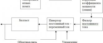
Electronic ballast (EPG) is a complex device with many electronic elements. Block diagram of such a device is shown in Fig. 4.
Fig.4. Block – electronic ballast circuit (EPG)
The main difference between electronic ballasts and conventional ballasts is the presence of an inverter, which, using transistor switches, converts a mains voltage of 50 Hz into a voltage with a frequency of 30-40 kHz. Thanks to this, the size and dimensions of this device are reduced. When the circuit is turned on, the LL cathodes heat up, electron “clouds” form near them, and a resonant voltage of about 600 V appears on a capacitor connected in parallel with the lamp, which is sufficient to ignite the lamp.
Fig.5. Electronic ballast device for fluorescent lamps
After the LL is turned on, the voltage across it drops to operating level, and the current is limited by the balanced choke.
Connection diagram via inductor
In order for the DRL lamp to work properly, the correct connection diagram for this device is necessary. Thanks to proper installation, lighting such a llama will not be any problem, and it will always work efficiently and without failures.
In addition, an incorrect connection increases the risk that the device will deteriorate and burn out ahead of time or at all, when first turned on.
The connection diagram is quite simple and represents a circuit of a series-connected inductor and the DRL 250 device itself. The connection is made to a 220 volt network and operates at a standard frequency. Therefore, they can be easily installed on a home network. The throttle works as a stabilizer and work corrector. Thanks to it, the light source does not flicker, operates continuously, and even with an unstable input voltage, the luminous flux remains unchanged.
Connecting DRL via throttle
A chokeless connection is not possible, as the lamp will burn out immediately. To start, the circuit must be supplied with a fairly high voltage, which sometimes reaches a level equivalent to two or three incoming voltages.
As previously mentioned, the drl device does not light up immediately. In rare cases, complete warm-up and start of operation at full power may take fifteen minutes.
Advantages and disadvantages
Comparative characteristics of two types of ballasts are given in the table.
| № | PRA | electronic ballasts |
| 1 | Simple, clear design | Complex circuit |
| 2 | Low price | Relatively high price |
| 3 | Large weight and dimensions | Compact device |
| 4 | Presence of flicker (100 Hz) | No flicker |
| 5 | Long start-up time | Instant launch |
| 6 | Difficulty starting at low temperatures | No difficulties |
| 7 | Low efficiency and cos φ | High efficiency |
| 8 | Doesn't work at low voltage | Wide voltage range |
| 9 | LL wear out quickly | LL work full term |
Prices for Electronic ballasts for fluorescent lamps
Prices for electronic ballasts for fluorescent lamps
How to connect a lamp
A fluorescent lamp can be connected in several ways. The choice depends on the operating conditions and user preferences.
Connection using electromagnetic ballast
A common connection method is using a starter and electronic ballasts. The mains power starts the starter, which closes the bimetallic electrodes.
The current in the circuit is limited by an internal choke resistance. The operating current can be increased almost three times. The rapid heating of the electrodes and the appearance of the self-induction process cause ignition.
Connection using electronic ballasts
Comparing the method with other schemes for connecting fluorescent lamps, we can formulate the disadvantages:
- significant energy consumption;
- long startup, which can take 3 s;
- the circuit is not capable of functioning at low temperatures;
- unwanted stroboscopic blinking, which negatively affects vision;
- Throttle plates may make a humming noise as they wear out.
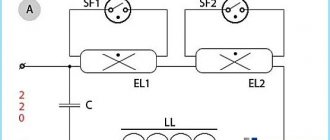
Two tubes and two chokes
In this case, a series connection of loads is implemented with a phase supplied to the resistance input.
The output is connected through the phase to the contact of the lighting device. The second contact is routed to the desired starter input.
Scheme with two tubes and two chokes
From the starter, the contact goes to the lamp, and the free pole goes to the zero of the circuit. A second lamp is also connected. The choke is connected, after which the bulb is mounted.
Connection diagram for two lamps from one choke
To connect two lighting fixtures from one stabilizer, you will need two starters. The circuit is economical, since the choke is the most expensive component of the system. The diagram is shown in the figure below.
Connection diagram for two lamps from one choke
Electronic ballast
Electronic ballast is a modern analogue of a traditional electromagnetic stabilizer. It significantly improves the startup of the circuit and makes using the lighting device more comfortable.
The current supplied to the load is rectified through a diode bridge. At the same time, the voltage is smoothed out, and the capacitors guarantee a stable supply of electricity.
Connection using electronic ballast
In this case, the transformer windings are turned on in antiphase, and the generator is loaded with high-frequency voltage. When a resonant voltage is applied inside the flask, a breakdown of the gaseous medium occurs, which generates the necessary glow.
Immediately after ignition, the resistance and voltage supplied to the load drop. Starting up using the circuit usually takes no more than a second. Moreover, you can easily use lighting sources without a starter.
Using Voltage Multipliers
Using Voltage Multipliers
The method helps to use a fluorescent lamp without electromagnetic balancing. In some cases, it is the most effective and extends the service life of the device. Even burnt-out devices can work for some time at powers not exceeding 40 W.
The rectification circuit provides significant acceleration and the ability to double the voltage. To stabilize it, capacitors are used.
It is important to remember that fluorescent light bulbs are not designed to operate with direct current. Over time, mercury accumulates in a certain area, reducing brightness. To restore the indicator, it is necessary to periodically change the polarity by turning the flask over
You can install a switch so you don’t have to disassemble the device
To restore the indicator, it is necessary to periodically change the polarity by turning the flask over. You can install a switch so as not to disassemble the device.
Connection without starter
Connection diagram without starter
The starter increases the heating time of the device. However, it is short-lived, so users are thinking about connecting lighting without it through secondary transformer windings.
Repair
If a lamp with an LL powered by a ballast fails, along with other elements of the circuit, it is necessary to check the performance of the inductor. The following malfunctions are possible:
- overheat;
- winding break;
- closure (full or interturn).
To check the throttle, you need to assemble the circuit shown in Fig. 6.
Fig.6. Circuit for checking the throttle
When the circuit is turned on, three options are possible: the lamp is on, the lamp is off, the lamp is blinking.
In the first case, there appears to be a short circuit in the throttle. In the second case, there is obviously a break in the winding. In the third case, it is possible that the inductor is intact and it is necessary to look for a fault in another element of the circuit. To be completely sure, you need to let the circuit run for 0.5 hours. If it turns out that the inductor is very hot, this indicates a short circuit between the turns of the winding.
The light does not light, checking the starter is working properly.
Since everything has a finite service life, it happens that the lamp does not light up. "Who is guilty?". It’s definitely not a choke anymore; interturn short circuits are isolated cases. Lamp or starter?
Repairs are usually carried out at a modular level. Replace with a known good item. Repair at the component level is not practical.
If components are missing, the fault will have to be identified. It is advisable to look at all the wiring of the lamp, since if it does not work, it is not necessarily the starter or the lighting device itself that is to blame. The possibility of poor contact, for example in pads or connectors, cannot be ruled out.
If you decide to repair it yourself, be sure to follow the safety rules! Lighters use high voltage in their work. There is a risk of electrical injury! Do not touch live parts of the circuit under voltage.
You need to start by checking the voltage in the network. A reduction of more than 20 percent does not guarantee stable operation of older modifications of the starter for fluorescent lamps.
First you need to check the wiring. Using a tester, you need to measure the supply voltage. Let's assume that it exists and is normal. To clear your conscience, you can also measure the resistance of the inductor winding to see if there is a break or an interturn short circuit. This is a very rare case. Let's say this element is working. That leaves either the lamp or the starter.
First, let's open the starter, you need to inspect its insides. The first thing we do is inspect the integrity. The contacts in the bulb should not be in a solder joint; visually there should be a distance between them. The capacitor should not show signs of destruction. You can do it differently, connect the starter to an incandescent lamp with a power of 40 to 60 Watts (no more) and apply an alternating voltage of 220 Volts according to the diagram below.
Connection diagram of an incandescent lamp with a starter
If the filament does not light up or lights up constantly, without short-term shutdowns, then such a starter is considered inoperative. It is not economically feasible to repair it; the cost is not high. If the test circuit works, then the lighting fixture is most likely faulty.
It can also be checked. Since at some point the contacts of a working starter close, the gas-discharge lamp can be lit “manually”. A mechanical button without fixation is used instead of a trigger device. When power is supplied to such a circuit, when you press the button, the fluorescent lamp should light up, this will indicate a starter malfunction. If this does not happen, you will have to replace the gas discharge lamp. Cases of simultaneous failure of two elements are quite rare.
If an electronic ballast is used, then it is worth checking the lighting device itself. If the new one works and gives an even glow, then the old one must be replaced.
It is possible to repair the ballast. They are usually repairable. But this will require knowledge of electronics. Measuring equipment will be needed. Without the necessary qualifications, such repairs are impossible.
- Related Posts
- Quartz lamp for home disinfection
- Relevance of LED lighting in 2022: efficiency, pros and cons
- Why do you need electronic ballasts (electronic ballast) for fluorescent lamps?
Discussion: 2 comments
- Egor:
My friend and I tested a pack of starters using this method. I was electrocuted in the process. The starter, connected directly to 220, successfully detonated, leaving a message from the other world on the retina, burning the power wires and scalding the socket.PS, as a person who saw this lightning, I want to say that this should be repeated only in cases of complete idleness and lack of self-preservation instinct.
PPS is a cool spectacle, but the method works, we managed to test some of the starters.
Answer
Vampaza:
Hello, Egor. I'm glad everything worked out okay, electric current is no joke. For this method, it is best to use an incandescent lamp of no more than 40 W, make sure the wires are insulated and the circuit is assembled correctly. And, of course, first you should visually inspect the starter itself; do not connect a starter that has deformation, places of melting and burning.
Answer
Starting LL without throttle
Circuits for turning on a LL without a choke, as a rule, are a DC power source in the form of a multiplier. One of the circuits of such a source is shown in Fig. 7. An ordinary incandescent lamp is used as a current limiter in the circuit.
Fig.7. Circuit for turning on fluorescent lamps without a choke
In such a circuit, the voltage across the LL reaches 700 V in approximately 25 ms.
How to connect correctly
Connecting fluorescent lamps is carried out using various options. With throttle, with ballast, with or without starter. The following article provides a detailed description of each method.
With and without throttle
A luminescent installation cannot simply be lit - it requires an igniter and a current conductor. In small factory products, all these nuances are taken into account and built into the body, and the buyer only needs to screw the light bulb into a suitable lamp/floor lamp shade and press the switch.
And for larger light bulbs, a ballast is required, which can be either electromechanical or electronic.
For proper connection and uninterrupted operation of the light bulb, you need to know the circuit.
Here we consider the step-by-step connection of two tubular fluorescent lamps to the network using a starter unit. To operate, you must have two starters and a choke, the type of which must necessarily match the type of lamp.
It is also necessary to remember about the total power of the starting apparatus; it should not be higher than that of the choke.
When connecting the power cable to the light bulb, you must remember that the inductor will act as a current limiter.
Therefore, the phase conductor must be connected through it, and the neutral cable must be connected to the product.
This connection diagram is suitable for large lighting lamps. And smaller models are equipped with a built-in launch and adjustment device - a portable electronic ballast, which is located in the housing.
Connection without using a choke
This connection option will be more difficult and not suitable for a beginner.
For operation, you can use a diode bridge with several capacitors and an incandescent lamp connected in series as a ballast.
The main advantage of this connection is that you can turn on not only a regular lamp without a choke, but also a damaged one, in which there are no spirals.
For products with a power of 18 watts, you must take the following elements:
- diode bridge GBU405;
- capacitor 2NF (up to 1 kV)
- capacitor 3NF (up to 1 kV)
- fluorescent lamp 50 W
For higher power tubes, you need to increase the volume of the condenser. After all, the circuit is connected to daylighting.
With electronic ballast
It is easy to carry out connection work using electronic ballasts for luminescent products if a person has basic electrical skills. In fact, the product will contain the block itself, an element of wires and fluorescent lamps.
First, you need to choose a convenient place in the lamp body to connect the electronic control unit, relying on the practical arrangement of terminals that are located on the body.
Secure it to the body using self-tapping screws and a simple screwdriver. Connect the control unit to the product and the connection terminal.
The program for connecting two luminescent products is the same, only they are switched on in series, so the power of the control unit must be greater. Using the same scheme, you can connect three or more light bulbs.
After completing the work, you need to make sure that all wires are connected correctly, and only then fix the lamp in place. After checking the absence of voltage in the electrical network with a voltmeter, connect the lamp to the electrical wiring.
Finally, you need to turn on the voltage to check the operation of the fluorescent lamp. If everything was done correctly, it will be noticeable immediately.
The lamps will turn on immediately, no need to wait until they warm up, and they will also stop making noise, flickering will disappear, and the brightness will be much higher.
If a person is not confident in his ability, then it is better to call a specialist for this work.
With starter
The connection diagram for a fluorescent lamp with a starter will be the easiest to complete. Here, as an example, we will take a 40 W light bulb. The choke should be of the same power, and 60 W will be enough for the starter.
Step-by-step connection according to the diagram:
- Install the starter in parallel to the protruding side contacts on the edges of the fluorescent light bulb. These contacts look like pieces of filament from a vacuum bulb;
- now you need to start connecting the inductor to the contacts;
- Connect a capacitor to these contacts, not in series, but in parallel. Because of this, the capacitor will compensate for reactive power and reduce interference in the electrical network.
Anyone can implement such a simple scheme, but before turning on the light bulb, you need to measure the voltage in the network. Turn on the lamp only after testing with a multimeter.
Comparison of chokes for different types of lamps
Chokes are used in gas-discharge lamps of various types. In any case, they serve to limit the operating current of the lamp. However, such chokes are not always interchangeable.
Thus, Dnat and DRL lamps operate in arc discharge mode, while LL lamps operate in glow discharge mode. Different operating modes require different throttle characteristics. In addition, the difference is that the choke as a voltage source for ignition is used only in LL.
Note! In Dnat lamps, a special pulse device (IZU) is used for starting, and DRL lamps are started directly from a 220 V network.
Prices for choke for fluorescent lamps
Prices for choke for fluorescent lamps
The design of starters and chokes and the principle of their operation
Starter
consists of a small glass flask filled with gas. The flask is placed inside a metal or plastic housing. There are two electrodes on the underside of the starter that come into direct contact with the lamp wires during operation. There is sometimes a window on top of the starter. Starters often fail, but they are very easy to replace because they are removable.
Throttle
It is a coil in a metal sheath. The power is set to the same as the lamp itself. Without a choke, the lamp will not work. The choke ignites the mercury vapor in the lamp and limits the current supply. The choke stabilizes the voltage in the network if it is higher than the nominal one.
The principle of operation of the starter and throttle is that one element (the starter) starts the electrodes into operation, and the throttle supports this work. When the current is turned on in the circuit, the starter turns on first. It warms up the electrodes, increases the current supply to the device, and heats up the bimetallic plate of the starter. After the electrodes have warmed up, the contact opens and the current is transferred to the inductor. For some time, the choke accumulates voltage, the gas breaks through in the bulb, and the lamp lights up.
During operation, the current is evenly distributed between the inductor and the lamp, which ensures stable operation even under conditions of increased voltage. The throttle does not consume energy on itself, it just accumulates it and converts it.
Without a starter, it is basically impossible to turn on a lamp using certain chokes. It just won't light up. Whereas during further operation of the lamp, a starter is not needed. You can even pull it out if necessary and check it or replace it while the lamp is running. But subsequent activation will require a starter. It is also possible to operate the lamp without a starter, directly. In this case, the lamp is lit by a cold start, which significantly reduces its service life. The choke ensures the operation of the lamp. Without it, the lamp will not work.