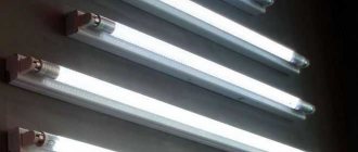
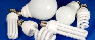
Many lighting systems have been using fluorescent lamps for a long time. They are distinguished by their efficiency, high performance and technical characteristics. Currently, compact devices have appeared in which the control system is freely located in the housing. Such lamps can be used in conventional lamps with threaded sockets.
Due to the design features and the use of ballasts, sometimes malfunctions occur during long-term operation, and then you have to repair fluorescent lamps yourself or call in specialists.
Electronic ballast repair
If it is not possible to quickly replace a failed electronic ballast, you can try to repair the ballast yourself. To do this, select the following sequence of actions to troubleshoot:
- First, check the integrity of the fuse. This breakdown often occurs due to overload (overvoltage) in the 220 volt network;
- Next, a visual inspection of electronic components is carried out: diodes, resistors, transistors, capacitors, transformers, chokes;
- If characteristic blackening of a part or board is detected, repairs are made by replacing it with a serviceable element. How to check a faulty diode or transistor with your own hands, having a regular multimeter, is well known to any user with a technical education;
- It may turn out that the cost of replacement parts will be higher or comparable to the cost of a new electronic ballast. In this case, it is better not to waste time on repairs, but to choose a replacement that is similar in parameters.
Starting with a burnt-out lamp
If the lamp does not light up due to a faulty starter and it is not possible to replace it, it is recommended to use starterless activation. In case of throttle failure, there is the possibility of throttleless activation. Let's look at these ways to eliminate the inclusion problem in a little more detail.
Throttleless activation
The connection diagram without the throttle is shown in the picture below. The method is quite complex; to implement it you will need knowledge in the field of electrical engineering.
Voltage is supplied following a short circuit of the filaments. After rectification, the voltage doubles, which is more than enough to start the light bulb. Thus, switching is carried out without using a throttle.
Capacitors C1 and C2 are taken at 600 V, for capacitors C3 and C4 you will need a voltage rating of 1000 V. After a certain period of time, mercury vapor will settle on one of the electrodes, the light will dim somewhat (or the lamp will stop lighting altogether). To get out of the situation, it is enough to change the polarity, that is, turn around the restored fluorescent lamp.
Starterless inclusion
There are lamps on sale that operate exclusively without the use of a starter. Such devices are marked with the abbreviation RS. If such a lamp is placed on a lamp equipped with a starter, it will burn out very quickly. The reason is that this lamp requires more time to heat up the coil. The starter's service life is short and the mechanism often fails. Because of this, it would be practical to consider starting the fluorescent lamp without a starter. The starterless connection circuit is shown in the following figure.
Electronic ballast circuits 4×18 (2×36)
EB 4×18 is used with inverting capacitors with a capacity of 5 pF. Thus, the resistance of this module can increase to 40 Ohms. Another feature of this circuit is the location of the choke element (it can be found below the dinistor).
Electronic ballast circuit 4×18
The circuit above uses only one transistor. The transformer performs the function of reducing and rectifying the current. This element protects the device from overloads, but there is also a fuse in the circuit.
Scheme for "Navigator"
Another 4×18 EB is “Navigator”. The circuit also contains a step-down transformer and a transistor. The main difference is the presence of a special regulator that allows you to change the output voltage. The capacitive resistor also distinguishes this circuit from the previous one.
Note! Here two capacitors with a capacity of 5 and 7 pF are used. This allows you to create resistance up to 40 ohms
This circuit does not use a fuse.
Scheme 2x36
The 2x36 ballast circuit includes a transceiver for expansion. The device is connected using an adapter device. As in the previous versions, there are capacitors, but their capacitance is smaller, only 4 pF. The circuit is distinguished by the presence of thyristors and frequency regulators. For most models of modules of this type, you can see two rectifiers in the circuit. The operating voltage of such a ballast is 200 V, and the frequency is 55 Hz.
You may be interested in Current through a capacitor
Electronic ballast 4x18 is a necessary device to maintain the integrity of fluorescent lamps. There are several schemes to connect it. You can choose the most suitable and easiest to implement.
ATTENTION! LECTURE SITE.ORG is conducting a weekly survey. TAKE PART. JUST 1 MINUTE.
Repair of fluorescent lamps. Replacing the electronic ballast
Sometimes such a malfunction occurs, after installing and connecting a lamp with two fluorescent lamps, the lamp works properly. Several months pass and the lamp begins to turn on with one lamp. You start turning the lamp in the sockets, change the starter, but there is no result. What to do and what to do, how to repair a lamp with fluorescent lamps yourself?
Lamp with two fluorescent lamps
First, let's look at the diagrams of such lamps with fluorescent lamps:
The diagram in Fig. 8.1 contains:
· two fluorescent lamps;
A fluorescent lamp has two filament coils. The lamps, starter and throttle are connected in series in the electrical circuit. The capacitor is connected in parallel.
The diagram in Fig. 8.2 contains:
· two fluorescent lamps;
Connecting fluorescent lamps in Fig. 8.2 is no different from the connection diagram for lamps in Fig. 8.1. Two wires, phase and neutral, have a branch in this circuit.
And the simplest circuit of a lamp with one lamp is shown in Fig. 8.3, where the capacitor, lamp and starter in the circuit are connected in parallel. The inductor is connected in an electrical circuit - in series.
Similar lamps are also found with three lamps. The very essence of the matter is not this - not the number of lamps.
Malfunctions of fluorescent lamps
The reasons for not turning on a lamp with one lamp or a lamp consisting of two lamps or more, when one of the lamps of the lamp does not turn on, may be the following:
1. malfunction of the lamp itself;
2. no contact with the throttle;
3. no contact with starter;
4. break in the wires.
You can check the electrical circuit of the lamp and determine where exactly the break is located with a probe. After you have purchased the lamp, check all the contact connections of the lamp.
Main functions
It is not possible to connect fluorescent light sources directly to the electrical network. There are the following reasons for this:
- to create a persistent discharge in a fluorescent lamp, it is necessary to preheat its electrodes and apply a starting pulse to them;
- Since gas-discharge light sources have a negative differential resistance, they are characterized by an increase in current strength after entering the operating mode. It must be limited to prevent the light source from failing.
Based on the reasons described above, it is necessary to use ballasts.
Electromagnetic type ballasts
Operating principle and some features of the device
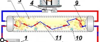
It is impossible to begin preventive measures or troubleshooting without carefully studying all the characteristics and operating principle of a fluorescent lighting device. First, let's define the source of light radiation - this is a lamp, which consists of a U-shaped or cylindrical bulb with air removed from it. The internal part is filled with vapors of inert gas and mercury. The filaments, with pairs of contacts located on them, are located at the edges of the bulb.
A gas-discharge lamp with a parallel-connected noise-suppressing capacitor serves as a starter for starting. The contacts close when voltage is applied. This process occurs due to the appearance of a glow discharge in the space between the electrodes. An important nuance is that at least one of this pair of elements must be bimetallic. The discharge causes the electrodes to heat up and they close. If desired, everything that happens can be seen through the inspection window in the housing.
Current flows in the following order - through series-connected threads, contacts and inductor. The formation of free electrons begins on threads coated with a special composition. What happens is called thermionic emission. The elements that appear contribute to the emergence of free charges inside the device, which are able to support the passage of current. The inductor has an inductive reactance that limits the passage of current in the filaments during heating.
The process of self-inductive emf appearing in the inductor is carried out after the electrodes have cooled and opened. The rapid acceleration of electrons and the occurrence of their movement occurs due to the combination of mains voltage with a high voltage pulse. Ionization of inert gas molecules is a consequence of the process of their collision with the resulting electrons. As a result, a very stable discharge is formed, with a current limited by the inductance of the inductor.
The starter is deactivated by bridging it with a lit lamp. Sometimes there is a situation where the fire does not occur. In such cases, the entire process is repeated cyclically until the moment when the startup is completed or any component fails. Filtering and eliminating interference during operation is the responsibility of the capacitor in the circuit. It is connected in parallel to the network terminals.
Schematic diagram
This is a large part of this electronic ballast; the Chinese did not include the inductor and capacitor here.
Actually, a diagram faithfully copied from a printed circuit board. The rating of the electronic components that made it possible to do this was determined not only “by appearance,” but also using measurements, with preliminary desoldering of the components from the board. In the diagram, the resistor values are indicated in accordance with the color coding. Only with regard to the choke, I allowed myself not to unwind the existing one to determine the number of turns, but measured the resistance of the wound wire (1.5 Ohms with a diameter of 0.4 mm) - it worked.
First assembly on the circuit board. I carefully selected the component values, regardless of size and quantity, and was rewarded - the light bulb lit up the first time. Ferrite ring (10 x 6 x 4.5 mm) from an energy-saving light bulb, its magnetic permeability is unknown, the diameter of the wire of the coils wound on it is 0.3 mm (without insulation). The first start-up is mandatory through a 25 W incandescent light bulb. If it is on and the fluorescent one initially blinks and goes out, increase (gradually) the value of C4, when everything worked and nothing suspicious was found, and removed the incandescent lamp, then reduced its value to the original value.
To some extent, focusing on the printed circuit board of the original source, I drew a signet for the existing suitable case and electronic components.
I etched the scarf and assembled the diagram. I was already looking forward to the moment when I would be satisfied with myself and glad to be. But the circuit assembled on a printed circuit board refused to work. I had to delve into and select resistors and capacitors. At the time of installation of the electronic ballast at the site of operation, C4 had a capacity of 3n5, C5 - 7n5, R4 resistance of 6 Ohms, R5 - 8 Ohms, R7 - 13 Ohms.
The lamp “fit” not only into the design; the lamp, raised all the way up, made it possible to comfortably use the shelf inside the secretary niche. Babay made the “room” feel comfortable.
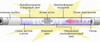
A fluorescent lamp (LL) is a glass tube filled with an inert gas (Ar, Ne, Kr) with the addition of a small amount of mercury. At the ends of the tube there are metal electrodes for applying voltage, the electric field of which leads to gas breakdown, the occurrence of a glow discharge and the appearance of electric current in the circuit. The glow of the gas discharge is pale blue and very weak in the visible light range.
But as a result of an electrical discharge, most of the energy passes into the invisible, ultraviolet range, the quanta of which, entering phosphorus-containing compounds (phosphor coatings), cause a glow in the visible region of the spectrum. By changing the chemical composition of the phosphor, different glow colors are obtained: for fluorescent lamps (FLLs) various shades of white have been developed, and for decorative lighting you can choose lamps of a different color. The invention and mass production of fluorescent lamps is a step forward compared to low-efficiency incandescent lamps.
Extending the life of a light bulb
Even at the very beginning of the mass use of fluorescent lamps, radio amateurs adapted to extend the life of burnt-out devices. The inclusion of such light sources was ensured by increasing the voltage directed to the electrodes of the light bulb.
The voltage is increased according to a circuit that involves a full-wave multiplier using capacitors and diodes. Thanks to this approach, there is a voltage peak exceeding 1000 V on the electrodes of the lamp when it is turned on. This is enough to carry out cold ionization of mercury vapor and create a discharge in the gaseous environment of the bulb. As a result, it becomes possible to ignite and stable glow of a fluorescent lamp even with a burnt-out spiral.
The main disadvantage of the circuit is that the voltage rating of the capacitors is too high, which should not be less than 600 V. Such a high voltage makes the device too bulky. Another disadvantage is the use of direct current, due to which mercury vapor accumulates near the anode. For this reason, the light bulb must be switched from time to time by removing it from the holders and turning it.
The resistor acts as a current limiter, since otherwise the light bulb cannot be broken. You can wind the resistor yourself. For this you will need nichrome wire.
Instead of a resistor, 127 V incandescent light bulbs with a power of 25 to 150 W are most often used. It is necessary that the power of the lamp used instead of a resistor be significantly higher than the power of the fluorescent lamp.
The nominal values of other components, calculated taking into account the fluorescent lamp power, are shown in the following table:
According to the data given in the table, the resistance and power of the diffuser bulb arises due to the parallel connection of several 127 V light sources. It is best to replace the diodes with imported products with similar parameters. As for capacitors, they must operate at a voltage of at least 600 V.
Circuits of electronic ballasts for fluorescent lamps
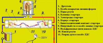
Electronic ballasts are an electronic board filled with electronic components. The circuit diagram of the connection (Fig. 1) and one of the options for the ballast circuit (Fig. 2) are shown in the figures.
Electronic ballasts can have different circuit designs depending on the components used. The voltage is rectified by diodes VD4–VD7 and then filtered by capacitor C1. After voltage is applied, capacitor C4 begins charging. At a level of 30 V, dinistor CD1 breaks through and transistor T2 opens, then the self-oscillator on transistors T1, T2 and transformer TR1 is switched on. The resonant frequency of the series circuit of capacitors C2, C3, inductor L1 and generator are close in value (45–50 kHz). The resonance mode is necessary for stable operation of the circuit. When the voltage on capacitor C3 reaches the starting value, the lamp lights up. At the same time, the regulating frequency of the generator and voltage are reduced, and the inductor limits the current.
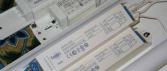
Photo of a typical electronic ballast device
Electronic ballasts for compact LDS
Relatively recently, fluorescent energy-saving lamps, adapted for standard sockets for simple incandescent lamps - E27, E14, E40, have become widely used in everyday life. In these devices, the electronic ballasts are located inside the socket, so repairing these electronic ballasts is theoretically possible, but in practice it is easier to buy a new lamp.
The photo shows an example of such an OSRAM lamp with a power of 21 watts. It should be noted that at present, the position of this innovative technology is gradually being occupied by similar lamps with LED sources. Semiconductor technology, constantly improving, makes it possible to quickly achieve prices for LDS, the cost of which remains practically unchanged.
OSRAM lamp with E27 base
Why do you need ballasts?
Before we start talking about the throttle, let's figure out what ballasts are and what they are needed for. In order to answer these questions, it is necessary to understand how a fluorescent lamp (FLS) works. Let's take a look at its schematic representation.
In front of us is a glass flask in the form of a tube, into the ends of which two tungsten spirals are soldered - the anode and the cathode. The tube itself is filled with an inert gas with a small addition of mercury. If operating voltage is applied to the anode and cathode, the lamp will not light up - the resistance of the inert gas is too high, and there will be no current between the electrodes.
In order to start the device, it is necessary to warm up the coils. As soon as they warm up, thermionic emission begins, the same as in a conventional vacuum tube for radio receivers. Current will begin to flow between the electrodes, and mercury vapor will begin to emit ultraviolet light. When ultraviolet light hits the phosphor, it causes it to glow brightly. UV radiation itself is almost completely absorbed by glass and phosphor.
The start of the DLS is ensured by a special device - a starter, which briefly supplies voltage to the coils (we’ll talk about its switching circuit later). It is the starting part of the control gear.
Starters for launching DLS
You can make the lamp work (as they say, “start”) in another way, by briefly applying increased voltage to the electrodes. This is exactly how electronic ballasts work, which we’ll talk about later.
But after starting the LDS, new problems begin: the glow discharge in the bulb turns into an arc and instantly leads to a short circuit. To prevent this from happening, the current through the lamp must be limited during operation. This role is played by another device - electromagnetic ballast. It is the regulating part of the ballast equipment.
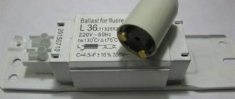
Electronic ballasts for LDS with a power of 36 W
Thus, without a starter the lamp will not start, without ballast it will burn out. The complex of these two devices is called ballast control. Now, I think you understand why ballasts are needed, and that you can’t do without them.
Important! The power of the choke must match the power of the lamp. Otherwise, the lamp will either go out immediately, or will not start at all, or will burn out.
Troubleshooting and Troubleshooting
To begin with, we must remember that an electroluminescent lamp performs its lighting functions only when all its components work in harmony - the lamp itself, the ballast, which can be either electromechanical or electronic. Thus, the reasons for the malfunction of the lamp can be either in the circuitry of the ballasts, or it can be a failure of the LDS due to its aging or violation of operating conditions.
It is best to check a fluorescent lamp (lamp) if you have a working analogue. It is necessary to provide convenient access to all its components. In this way, you can correctly analyze the malfunction and give recommendations for elimination, even if you repair it yourself. We'll tell you how to check a fluorescent lamp at home.
Integrity of electrode spirals
The electrode spirals are located inside the gas-filled LDS tube and during production are soldered to the legs of the lamp bases. They are located in the end parts of the flask. Thus, using a multimeter in resistance measurement mode, you can ring a fluorescent lamp.
Repair of fluorescent lamps
After repairing or replacing the ballast, we reinstall the lamps in place and turn on the current. If they still do not light up, and the ballast is working properly, then the problem is in the lamps themselves, there are only 3 reasons for the malfunction - burnout of the filaments, aging of the lamp, or gas leakage (this happens if the pin contacts of the base are poorly soldered). If it is impossible to do anything with the second two options, then the first is quite curable. To do this, you just need to connect the lamp according to an alternative circuit (Fig. 13). Let me make a reservation right away - it is not recommended to do this with new lamps - the method is quite aggressive and when used, the lamp quickly becomes unusable. The circuit is quite simple and consists of only 4 parts - an inductive (don’t confuse it with an electronic one, it’s just a coil that does not contain radio elements) ballast, a 1-4 uF x 400 V capacitor, a push-button switch, and, of course, the lamp itself.
Fig. 13 Lamp connection diagram
The operating principle of this circuit is extremely simple - when you press a button, a high voltage is supplied to the lamp through a capacitor, sufficient to ignite it. After the lamp is ignited, the button is released; it, together with the capacitor, is needed only to warm up the lamp and create a glow discharge in it, after which the lamp operates in normal mode. This connection scheme, of course, does not make the lamp eternal, but it allows you to extend its life by a couple of months.
Repair instructions
Now we will look at the main faults that can be fixed without much investment. Let's start with the electronic ballast, because in its circuit there are quite a lot of elements that can fail, and besides, tubular fluorescent lamps with electronic ballasts are more common today.
Ballast
The most common fault is transistor breakdown. This failure can only be determined by removing the transistors from the circuit and checking them with a tester. In the whole transistor, the transition resistance
400-700 Ohm. As the transistor burns, it pulls a resistor in the base circuit with a nominal value of 30 ohms.
There is also a fuse or a low-resistance 2-5 Ohm resistor on the board; most likely it will have to be replaced, at which point the repair will end. You may additionally have to change the diode bridge or its elements.
A breakdown of 47n film capacitors (half a microfarad) or a resonance capacitor in the filament circuit is rare. There have been cases when all of the above is intact and in good order, but the lamp does not work, the reason lies in the DB3 dinistor. If you have checked all the elements of the circuit, then try replacing the dinistor.
You may decide that it will be cheaper to purchase a new electronic ballast than to repair a broken one. Replacing the starting equipment should not be difficult, because the connection diagram is printed on the device itself. Upon careful study, it is easy to understand, L and N are terminals for connecting to a 220V network.
Operating principle of the starter
Whatever circuit is used to start a fluorescent lamp. The general operating principle remains unchanged. In principle, similar processes occur when using a throttle and starter. There are only three phases:
- Initial heating of the electrodes. In electronic ballast, this occurs by a fairly gentle increase in voltage on the tungsten filaments.
- Arson. At this moment, the circuit delivers a high-voltage pulse (usually about one and a half kilovolts). This is enough for electrical breakdown of gas and mercury vapor. The ignition voltage of fluorescent lamps is significantly higher than the combustion voltage.
- Combustion. After a high-voltage pulse, the circuit reduces the voltage to that required to maintain the glow discharge. The AC frequency at the electrodes can reach 38 kHz depending on the circuit.
In electronic ballasts, the igniting impulse is provided by an electronic circuit. In the classical scheme - due to the energy accumulated by the inductor. Warming up of the electrodes is also provided by electronic ballasts. With a starter switching circuit, the electrodes warm up at the moment the starter contacts close. It can be replaced with a push button.
Electronic ballast device
An electronic ballast is a complex electronic device. Includes:
- Interference filter: necessary to level out the influence of interference from and into the electrical network;
- Rectifier: needed to convert AC to DC;
- Optional: power corrector;
- Anti-aliasing filter: used to reduce ripple;
- Inverter: increases the voltage to the required level;
- Ballast: analogue of an electromagnetic choke.
Connection diagrams
The development of such an electronic device was carried out to minimize the design of the lamp and replace the large inductor and starter with one single module, which is connected to the AC power supply and to the electrodes of the fluorescent light source.
Electronic ballasts are devoid of all the disadvantages of classical connection schemes.
There are modules designed to simultaneously connect four lamps.
Connecting electronic ballasts to four lamps
As is the case with one or two lamps, the circuit does not require any additional elements. The electronic ballast module is connected directly to the ll.
Connection diagram for electronic ballasts 4x18 W (Example: Navigator NB-ETL-418-EA3)
Connection diagram for electronic ballasts 2x36 W (Example: ELECTRONIC BALLAST ETL-236)
How to check the choke of a fluorescent lamp
The LDS works together with a choke, which is designed to regulate the current and prevent the coils from burning out due to overheating. This device is a winding of wire with a metal core. The fault may be in the throttle if:
- the lamp is buzzing loudly;
- the lamp lights up, but quickly goes out with the appearance of dark spots;
- LDS overheats during combustion;
- Inside the glass bulb there is strong flickering and running snakes.
The malfunction most often lies in a burnout or breakage of the winding, or loss of insulation. To find the cause, you need to measure the throttle resistance. If it is infinite, there is a winding break. Low resistance - loss of insulation, leading to an interturn short circuit.
Useful tips Connection diagrams Principles of operation of devices Main concepts Meters from Energomer Precautions Incandescent lamps Video instructions for the master Testing with a multimeter
Types of ballast
Different types of ballasts are grouped by implementation type: electronic and electromagnetic implementation. In addition, the models are classified according to the area of application for lighting devices, among which are:
- High frequency electronic ballast for fluorescent luminaires, with or without preheating. The first model increases the performance and service life of the device, and also reduces the noise effect. Ballast without preheating consumes less energy. High frequency ballast for sodium lamps. This is a less bulky ballast than conventional models installed on low-pressure lamps, easy to install, and with low energy consumption for its own needs.
- Electronic ballast for gas discharge devices. This model is usually designed for high pressure sodium and metal lamps, increasing their lifespan by up to 20% compared to the standard. The start-up time is reduced, as are the flashing effects. It should be noted that these ballasts are not suitable for all luminaires.
- Multi-lamp ballast. It has the advantage that it can be used with several types of fluorescent devices, including aquarium lighting, creating an optimal primer. It has the function of recording all lighting parameters in its memory.
- Digitally controlled ballast. This is the latest generation model, offering a lot of flexibility and modularity when installing luminaires. This improves the economic aspect of the LED lamp and the brightness comfort. At the same time, it is the most expensive model.
Electromagnetic implementation
Magnetic ballasts (MB) are devices with old technology. They are used for the fluorescent lamp family and some metal halide devices. They tend to cause humming and flickering because they regulate current gradually. MBs use transformers to convert and control electrical power. When the current arcs through the light fixture, it ionizes a larger percentage of the gas molecules. The more of them are ionized, the lower the gas resistance. Thus, without MB, the current will rise so high that the lamp will heat up and destroy.
The transformer, which in MB is called a “choke”, is a wire coil - an inductor that creates a magnetic field. The more current flows, the greater the magnetic field, the more the current growth slows down. Because the process takes place in an alternating current environment, the current flows in one direction for only 1/60 or 1/50 of a second and then drops to zero before flowing in the opposite direction. Therefore, the transformer only needs to slow down the flow of current momentarily.
Electronic implementation
The performance of electronic ballasts is measured using various parameters. The most important is the ballast factor. This is the ratio of the luminous output of a lamp, controlled by the EB in question, to the luminous output of the same device, controlled by a reference ballast. This value ranges from 0.73 to 1.50 for EB. The significance of this wide range lies in the levels of light output that can be achieved using a single EB. This finds great use in dimming circuits. However, it has been found that too high and too low ballast factors degrade luminaire life due to lumen wear resulting from high and low current, respectively.
You might be interested in: Features of connecting IZU for DNAT
Electronic implementation
When EBs are to be compared within the same model and manufacturer, the ballast efficiency ratio is often used, which is the ratio of the ballast ratio expressed as a percentage to power and provides a relative measurement of the system efficiency of the entire combination. A measure of the efficiency of a ballast, power factor (PF) is a measure of the efficiency with which the EB converts supply voltage and current into usable power supplied to the lamp with an ideal value of 1.
Radio as a hobby
Repairing a fluorescent lamp
For several years I have been using a lamp with a tubular 18-watt fluorescent lamp. It (the lamp) did not cause any particular complaints... Apart from replacing burnt-out fluorescent lamps, there were no operational failures. But, as they say, nothing lasts forever...
Some time ago, when I tried to turn on the lamp, a bang was heard inside it, accompanied by a flash. The lamp was immediately de-energized, removed and pushed onto the far shelf in the pantry. Given its advanced age, the first decision was to throw the lamp in a landfill. Later, it was decided to try to repair it.
Let's start the renovation.
We disassemble the lamp and remove the fluorescent lamp. The first step is to check the lamp filament with an ohmmeter for breakage. The filaments turned out to be intact, and accordingly the lamp turned out to be in good working order and suitable for further use.
After opening the lamp, I was immediately struck by the terrible condition of the factory power cord, which was located inside the lamp body. The cord insulation cracked in many places, lost its elasticity and crumbled right under my fingers.
This is what the power cord looks like after ten years of use.
This state of the wire poses the following dangers:
-possibility of electric shock;
- the possibility of a short circuit and, as a result, fire;
Therefore, we change this cord first!
We continue to work... A popping sound inside the lamp clearly indicated a failure of the electronic ballast.
Removing the electronic ballast
A visual inspection did not reveal any burnt resistors. The mains fuse was also good. The mains fuse is the leftmost part on the ballast plate and is designated F1.
But the electrolytic capacitor with a nominal value of 4.7 µF x 400V turned out to be swollen
In order to carry out further repairs without blindness, I had to search the Internet for circuit diagrams of electronic ballasts. There are a great variety of them, and they are very similar to each other. The difference is only in the ratings of some parts, the presence/absence of additional protective elements and the type of transistors.
An attempt to compare the ballast diagram from my lamp with diagrams from the network showed that, in our case, additional elements were included in the ballast diagram. Therefore, in order not to rack my brains, I had to draw up a circuit diagram using a printed circuit board.
First of all, in such cases, we check the transistors. Both transistors turned out to be unusable with broken B-K junctions. This ballast uses transistors of the EB13003 type, which are analogues of the MJE13003 transistor, but have a different pinout from the original. This must be taken into account when replacing failed transistors.
Further inspection revealed that resistors R2, R3, R4, R5, R6, R7 had become unusable. The nature of the malfunction for all resistors is similar - an increase in resistance to 1 MΩ or more.
Failed elements are marked with red circles on the circuit diagram
All capacitors (except for the above electrolyte C2) turned out to be serviceable.
Instead of unusable ones, we solder in resistors of the MLT-0.125 type with the required values.
Instead of EB13003 transistors, we solder some Chinese type S13003.
We assemble the lamp in the reverse order.
Test activation... Everything worked. ))
The question of finding out the cause of failure of radio components is always interesting. In relation to this lamp, or more precisely, to its electronic ballast, my thoughts are as follows... After the repair, I noticed that the body of the lamp in the area where the electronic ballast is installed noticeably heats up. I didn’t pay any attention to this before. Heating indicates that the radioelements are operating under severe temperature conditions. In my opinion, this is one of the main reasons for the failure of radio elements. The first one that apparently failed due to overheating was the 4.7 µF x 400V electrolytic capacitor, which is a filter after the diode bridge. The deterioration of rectified voltage ripple suppression increased the level of voltages applied to the transistor junctions. Next, one of the transistors flew out, and then, according to the domino principle, another one flew out, along the way, the resistors in the base and emitter circuits burned out.. And that’s all.. Next was the repair.
Source: www.myhomehobby.net
Fluorescent lamps (FL) are still used for lighting today, despite the fact that LED lamps provide them with strong competition. Linear tubular lamps are most often installed in offices, garages, and factories; compact fluorescent lamps (CFLs) are installed at home and in the same types of premises as listed above. They have characteristic malfunctions, so in this article we will look at how to repair fluorescent lamps.
Description of design
Fluorescent lamps differ in the shape of the tubular bulb, they are:
This is typical for CFLs, where the bulb is a tube twisted into a spiral or U-shaped. This is necessary to reduce the size while maintaining the length and area of the emitted surface.
In general, the bulb of a fluorescent lamp is a glass tube into which mercury vapor and inert gases are pumped. There are two spirals installed in the flask, one at each of its ends.
When the discharge burns in the lamp, ultraviolet light is emitted to convert it into visible light; the inner surface of the bulb is covered with layers of phosphor.
Tubes come in different diameters and lengths. Typically, the longer the lamp, the more powerful it is.
As already mentioned, such lamps have two spirals. They are needed to heat the gases and power the lamp after it is started. Two pin contacts from the spirals come out of the flask on each side.
This connection method is called a pin socket of type G. Depending on the distance between the pins, sockets of type G13 and G5 are distinguished. In which the pins are located at a distance of 13 and 5 mm, respectively.
Power circuit and normal operation
Fluorescent lamps differ from ordinary lamps in that for them to work it is not enough to simply connect its terminals to a 220V AC network. The power supply circuit assumes the operation of a fluorescent lamp with a so-called ballast - ballast control device. They come in two types:
Electromagnetic ballasts are considered obsolete, but are still often used to this day. They are not as efficient and produce light with barely noticeable flickering (low ripple), but they are reliable and easy to repair. Therefore, let's look at them first.
To light a lamp, you need to break through its gas gap; to do this, you need to create a pulse of increased voltage. Therefore, an energy storage device – a choke – is installed in series with the lamp.
But such a scheme will still not work; it is necessary to control the process of heating the coils and the accumulation of energy. The spirals are heated to provoke the emission of electrons, which should result in a discharge in the ionized gas. In tubular fluorescent lamps the discharge is glowing.
System health check
After connecting the fluorescent lamp, you should make sure that it is working and that the ballasts are in good working order. To carry out the tests, you will need a tester with which to check the cathode filaments. The permissible resistance level is 10 ohms.
If the tester determines the resistance to be infinite, it is not necessary to throw away the light bulb. This light source still retains functionality, but it must be used in cold start mode. In the normal state, the starter contacts are open, and its capacitor does not allow direct current to pass through. In other words, the ringing should show a very high resistance, which sometimes reaches hundreds of ohms.
After touching the choke terminals with the ohmmeter probes, the resistance gradually decreases to a constant value inherent in the winding (several tens of Ohms).
It is not possible to reliably determine the turn-to-turn short circuit in the inductor winding using a conventional ohmmeter. However, if the device has an inductance measurement function and data on electronic ballasts, a discrepancy between the values will indicate a problem.
Let's get started
You can make such a lighting device with your own hands of any design. But it is better to choose an option with a removable top cover than to give preference to a monolithic design. So, in any case, it will be more convenient to carry out repairs. Here the manufacturing process involves the following steps:
- We make a frame around the perimeter. It is better to make it two-layer. The top layer will be decorative;
- We assemble the electrical system of the lamp according to the diagram;
make sure all contacts are securely insulated
In a situation with close water, this is vitally important. To do this, sealed tips should be placed on the ends of the lamps;
- we attach the entire electrical circuit to the plastic cover of the lamp;
- Next, using glue, fix a plexiglass rectangle on the bottom side of the device;
- We put a plastic cover on top on which fluorescent lamps are installed. The cover should be easy to remove so that the device can be repaired.
Almost finished product
If the cover is black, then it must be covered with white reflective film. For white plastic such manipulations are not carried out. Where the lamp connects to the aquarium, it is necessary to apply sealant to prevent condensation from penetrating into the lighting fixture. But before applying the sealant, do not forget to degrease the glass.
Classification of fluorescent lamps
According to the spectral radiation indicator, luminescent type devices are divided into 3 categories:
- standard;
- with improved color rendering;
- with special functional purposes.
Standard devices are equipped with single-layer phosphors, which allow them to emit different tones of white. The devices are optimal for lighting residential premises, administrative and production units.
Fluorescent lamps with improved light transmission are equipped with a phosphor with 3-5 layers. The structure allows high-quality reflection of shades due to increased light output (12% more than standard lamps). The models are suitable for shop windows, showrooms, etc.
Fluorescent lamps for specialized purposes are improved with the help of different compositions in the tube, allowing them to maintain a given spectrum frequency. The devices are used in hospitals, concert halls, etc.
The devices are divided into high and low pressure models.
High-pressure designs are optimal for installation in street lamps and high-power devices.
Low pressure lamps are used in apartments, administrative complexes, and industrial premises.
In appearance, LLs are presented in linear and compact versions.
The linear design of the flask is elongated, used for industrial premises, shopping centers, offices, medical institutions, sports organizations, factory floors, etc. The linear model is represented by different options for tube diameters and base configurations. Devices are identified by codes. A device with a diameter of 1.59 cm is marked on the packaging with a T5 sign, with a size of 2.54 cm - T8, etc.
Compact fluorescent lamps (CFLs) are a spiral-shaped glass tube and are designed for installation in apartments, offices, etc. CFLs are divided into 2 types, the main difference being the types of bases (standard and with a pin-shaped base).
Traditional base in the form of a thread and a code with a diameter size.
The pin type of the base is marked with the symbol “G”; The numbers indicate the distance between the pins. This lamp is optimal for installation in table lamps and pendant sconces in small rooms.
Fluorescent lamps differ in power (weak and strong). The power of a fluorescent lamp in W can exceed 80 units. Devices with low power are represented by products up to 15 W.
In terms of light distribution, devices can be directional (reflective, slot type) or non-directional.
Based on the type of discharge, devices are divided into arc, glow or glow discharge devices.
The scope of application of lighting devices differs (external, internal, explosion-proof, console).
External devices are suitable for decorating the outside of buildings, for lighting gazebos, decorating a yard, etc. When choosing, it is necessary to take into account the temperature conditions of the region.
Internal suitable for office and residential buildings. The devices are equipped with protection from moisture and dust. The body parts are connected in a hermetically sealed manner. The design of the lamps can be straight, pendant, designed for attachment to the ceiling surface.
Explosion-proof devices are designed for areas with a risk of explosions (warehouses, dye production workshops, etc.).
Console-type devices are mounted using special fasteners and have an individual housing.
Repair of LED lamps
Failures of LED lighting fixtures are often associated with a malfunction of the transformerless rectifier. In this case, the repair of lamps consists of testing low-resistance resistors, replacing a burnt-out capacitor, etc. The break is detected during the testing process: the resistors may outwardly look like serviceable parts.
The power supply is working - the master analyzes the status of the LEDs. An electrician installs new LEDs instead of burned out ones. A weak capacitor causes unpleasant flickering of lamps. The problem is solved by installing a more powerful part. Another repair option is to add a second capacitor.
We will help you repair your lamps and return light to your home, contact us!
How does LL work with electromagnetic ballast?
Pay attention to this connection diagram. Marking LL1 is a ballast
There is a gaseous environment inside fluorescent lamps. As the current increases, the voltage between the electrodes in the lamp gradually drops and the resistance is negative. The ballast is used precisely to limit the current, and also creates an increased short-term ignition voltage for the lamps, since there is not enough of it in a regular network. This element is also called a choke.
Such a device uses a starter - a small glow discharge lamp (E1). It contains two electrodes. One of them is bimetallic (movable).
In the initial position they are open. By closing contact SA1 and applying voltage to the circuit, the current does not initially pass through the light source, but a glow discharge appears in the starter between the two electrodes. The electrodes heat up, and the bimetallic plate bends as a result, closing the contact. The current passing through the ballast increases, heating the electrodes of the fluorescent lamp.
Next, the electrodes in the starter open. A process of self-induction occurs. The choke creates a high voltage pulse, which ignites the LL. The rated current passes through it, but then it drops by half due to a decrease in the voltage across the inductor. The starter electrodes remain in the open position as long as the light is on. And capacitors C2 and C1 increase efficiency and reduce reactive loads.
Connecting fluorescent lamps
Advantages of classic electromagnetic ballast:
- low cost;
- ease of use.
- noise of operating throttle;
- LL flicker;
- long lamp ignition;
- weight and large dimensions;
- up to 15% energy losses due to phase advance of alternating current voltage (power factor);
- poor activation in low temperature environments.
On a note! The problem of energy loss can be solved by connecting (in parallel to the network) a capacitor with a capacity of 3-5 μF.
What is ballast used for?
The current in a gas discharge grows like an avalanche, which leads to a sharp drop in resistance. To ensure that the electrodes of the fluorescent lamp do not fail due to overheating, an additional load is connected in series, limiting the amount of current, the so-called ballast. Sometimes the term throttle is used to refer to it.
Two types of ballasts are used: electromagnetic and electronic. The electromagnetic ballast has a classic transformer configuration: copper wire, metal plates. Electronic ballasts use electronic components: diodes, dinistors, transistors, microcircuits.
Incandescent lamps
For the initial ignition (start) of the discharge in the lamp in electromagnetic devices, a starting device is additionally used - a starter. In the electronic version of the ballast, this function is implemented within a single electrical circuit. The device turns out to be light, compact and is united by a single term - electronic ballast (EPG). The widespread use of electronic ballasts for fluorescent lamps is due to the following advantages:
- these devices are compact and light in weight;
- the lamps turn on quickly, but smoothly;
- absence of flicker and noise from vibration, since electronic ballasts operate at high frequencies (tens of kHz) in contrast to electromagnetic ones operating from mains voltage with a frequency of 50 Hz;
- reduction of heat losses;
- electronic ballast for fluorescent lamps has a power factor of up to 0.95;
- the presence of several, proven types of protection that increase safety of use and extend service life.
Conclusions and useful video on the topic
The video material, based on the practice of an electrician, tells and shows which of the two devices should be recognized by the end user as better and more practical.
This story once again confirms that simple solutions look reliable and durable:
Meanwhile, electronic ballasts continue to be improved. New models of such devices periodically appear on the market. Electronic designs are also not without drawbacks, but compared to electromagnetic options, they clearly show better technical and operational qualities.
Do you understand the principles of operation and connection diagrams of electronic ballasts and want to supplement the above material with personal observations? Or would you like to share useful recommendations on the nuances of repairing, replacing or choosing a ballast? Please write your comments on this entry in the block below.
How to choose the right one
Before choosing a device for lighting lamps, pay attention to the following characteristics:
- Type, power and number of lamps in the lighting scheme. The specification sheet for an electronic fluorescent ballast will indicate what types and configurations of fixtures are designed to operate the ballast.
- Start type - instant or programmed. If the lighting system is subject to frequent switching due to occupancy sensors or other factors, select “programmed start.” Otherwise, "instant" is the best choice.
- Ballast factor. The usual ballast factor (0.77 to 1.1) is the default value for most general lighting. A low ballast factor ({amp}lt;0.77) may be the most suitable ballast factor for applications where the full luminous output of the luminaires is not required, then it is appropriate as a way to save energy.
- A high ballast factor ({amp}gt; 1.1) is useful when the goal is to increase light output for areas such as warehouses or large retail stores. In this case, the user will receive approximately a 10% increase in luminous flux compared to the nominal illumination of the device.
- Input voltage. Some EBs provide universal voltage, others specific voltage. In any case, check the input voltage requirements - 120/277/347 V.
- Minimum starting temperature. Ballast specification sheets include temperatures that will vary depending on the type of fixture being controlled by the ballast. For example, EB can show a minimum initial temperature from −17 C to 30 C. Obviously, the variations are quite significant. Therefore, when choosing an EB, they proceed from the minimum and maximum air temperatures in the room.
- The normal connection diagram is parallel. This allows other lights to remain lit even if one bulb in the fixture goes out.
- Anti-stratification control: Strata are unwanted bright and dim areas that can form a standing wave structure along the entire length of the fixture. Streaks are more likely to occur when the lamp is operated at low temperatures. Manufacturers have developed ways to minimize these areas and often refer to the anti-stripping feature in the EB specification.
- Sound rating. An EV with an “A” rating will hum quietly, and one with a “D” rating will cause a pronounced noise. The importance of sound assessment depends on the purpose of the premises.
- In libraries, LLs with the quietest ballast are installed, while this parameter is not so important for warehouses.
- LED Transition: Some EV manufacturers have lists of instant and programmed starting ballasts that they call "LED Ready".
- Manufacturer's warranty.
READ MORE: Do-it-yourself cellar at the dacha: a step-by-step guide to arrangement
How to check a light bulb with a multimeter - instructions
A visual inspection does not always allow a qualitative assessment of the condition of an electric incandescent lamp; even with an intact spiral, the internal circuit may be broken. Therefore, it is better to trust devices that, if used correctly, will accurately indicate a malfunction. Let's look at how to check an incandescent light bulb with a multimeter.
Household 220-volt incandescent lamps for indoor lighting have the two most common standards of bases and sockets for them - E14 and E25, the numbers indicate the diameter of the threaded connection. The easiest thing, at first glance, is to screw a lamp with a whole spiral into the socket of another known-to-be-good lighting fixture and make sure that it works. But there is not always a lamp with a suitable socket on site, much less a working one. Therefore, multimeters are used; these devices are small-sized, lightweight, easy to use, even an amateur can work with them in dialing mode.
Setting the device to dialing mode
The term “continuity” means checking the electrical circuit for integrity and presence of contact. Every modern multimeter has such a mode, the classic arrangement of controls on devices, this is a packet switch in the center of the case, under the liquid crystal display. By turning it, the required modes are set; their letter and symbolic designations are indicated on the case in a circle, which experts understand well; in our case, this is the sign of a diode or buzzer.
Examples of locations of dialing symbols on different multimeters
In addition to the switch position, the contact test leads must be connected correctly. Above in the right photo this is clearly visible - in the lower right corner of the multimeter, a black probe is inserted into the lowest hole with a grounding sign and the letters “COM”. The red one is inserted into the connector above labeled “VΩmA”. After installing the controls in the desired position, you can carry out testing and dialing, but before that, make sure that the device is working. Connect the metal tips of the red and black probes; if the device is working properly, you will hear a characteristic buzzer tone. Zeros will appear on the screen, which means that there is no break or resistance in the electrical circuit; when the circuit is opened, the display will show “1”.
Checking the lamp
Place the tip of one probe to the central contact of the lamp, the second to the thread of the base, if the lamp is working, you will hear the buzzer working, the display will show numbers from 3 to 200. The value of the resistance of the spiral in Ω (Ohm) depends on the material and length of the spiral. To be safe, before testing, clean the areas where the probes touch with a file; they tend to oxidize.
In this way, you can not only check the light bulbs for serviceability, but also determine the approximate power consumption. If for some reason there is no inscription with the value on the glass bulb, for accurate measurements, set the device to the 200 Ohm measurement mode.
The red arrow indicates the measurement position within the range of up to 200 ohms
Using the above method, measure the resistance of the coil on the lamp. Without going into mathematical formulas for calculations, you can compare the ratio of resistance to lamp power using a pre-compiled table.
Table of the ratio of power to filament resistance of a 200 V incandescent lamp
Ω W 150 25 85 40 63 60 48 75 38 100 27 150
Resistance error may be ±2-3 ohms.
Incandescent lamps in 12 V vehicles are checked in a similar way, only it must be taken into account that in some cases in the headlights they have two spirals, for high and low beam. You can check tubular fluorescent lamps, they also have two spirals at the edges between the electrodes.
Design of a fluorescent tube lamp
But do not try to test compact fluorescent, economical halogen and LED lamps with E27 and E14 standard sockets using this method at home. These designs contain a circuit, an electronic connection and start unit, so the test is carried out using a different system. The issue of checking such light bulbs with a multimeter or another method requires a separate, detailed consideration.
Cost of lamp repairs
The cost of repairing lamps depends on the model of the lamp. Prices for repairing a regular ceiling lamp, chandelier, sconce or floor lamp will vary. Prices are determined by the complex of work performed and negotiated with each client individually. Below is an indicative list of works and prices
| Type of work | Price |
| Diagnostics | 200 rub. |
| Replacement and repair | |
| Regular cartridge | from 300 rub. |
| Non-standard cartridge | from 350 rub. |
| Wiring (chandelier, sconce) | from 300 rub. |
| Wiring (floor lamp) | from 350 rub. |
| Postings (in the horn) | 300 rub. |
| PRA | 400 rub. |
| Transformer | from 350 rub. |
| Throttle | 500 rub. |
| Starter | 200 rub. |
| Electronic elements, dimmer, touch switch | 100 - 450 rub. |
| Remote control/controller | 450 rub. |
| Buttons or switches (sconces) | 200 rub. |
| Plafonov | from 150 rub. |
| Lamp | from 150 rub. |
| Cost of additional services | |
| Painting the cartridge | 100 rub. |
| Assembly and disassembly of the lamp | from 400 rub. |
How to start a fluorescent lamp without a throttle
What do DIYers and radio amateurs advise doing in such cases? They recommend using the so-called chokeless circuit for switching on fluorescent lamps.
It uses a diode bridge, capacitors, and ballast resistance. Despite some advantages (the ability to start burnt-out fluorescent lamps), all these schemes are a waste of money for the average user. It is much easier for him to buy a new lamp than to solder and assemble this entire structure.
Therefore, first we will consider another popular method of starting LB or LD lamps with a burnt-out inductor, which will be available to everyone. What do you need for this?
You will need an old burnt out energy saving light bulb with a regular E27 base.
Of course, the circuit using it cannot be considered absolutely chokeless, since the choke is still present on the energy saving board. It’s just much smaller in size, since the housekeeper operates at frequencies of up to several tens of kilohertz.
This mini choke limits the current through the lamp and provides a high voltage pulse for ignition. In fact, this is an electronic ballast in a miniature version.
Previously, there was a large advertising campaign for replacing incandescent lamps with energy-saving ones. Today they are actively being replaced with LED ones.
It is not recommended to throw housekeepers into the trash, just like certain LED models.
Therefore, some conscientious and thrifty citizens who have not yet handed them over to special collection points store such products on their shelves in their lockers.
They change them for a reason. These bulbs, when in working condition, are very harmful to health, both in terms of light pulsation and dangerous ultraviolet radiation.
Although ultraviolet light is not always harmful. And sometimes it brings us a lot of benefit.
At the same time, do not forget that linear luminescent models equally have the same negative factors. They are the ones that actively scare those who like to grow plants under the light of phytolamps.
But let's get back to our energy savings. Most often, their luminous spiral tube stops working (the seal disappears, breaks, etc.).
In this case, the circuit and internal power supply remain intact and unharmed. They can be used in our business.
First you disassemble the light bulb. To do this, along the parting line, use a thin flat screwdriver to open and separate the two halves.
When separating, do not hold the glass tubular flask under any circumstances.
Next, pull out the board. On it, find the places to which the wires from the “filaments” of the bulb are connected. They usually come in the form of pins.
When disassembling, remember which pair is connected where. These pins can be located on one side of the board or on different sides.
In total you should have 4 contacts, where you should solder the wires in the future.
And of course, don’t forget about the 220V power supply. These are the same veins that come from the base.
All that needs to be done next is to solder two conductors to each contact on the board (from the former filaments of the tubes) and lead them to the side pins of the fluorescent lamp.
That is, there are two separate wires on the right and two wires on the left. After that, all that remains is to supply 220V voltage to the energy saving circuit.
The fluorescent light bulb will light up perfectly and work normally. And you don't even need a starter to start it. Everything connects directly.
If the starter is present in the circuit, it will have to be thrown out or bypassed.
Repair work
We repair a flashing lighting fixture in the following sequence:
- We check the voltage in the electrical network and the quality of the contacts.
- We replace the light bulb with a working one.
- If the lamp continues to blink, we replace the starter in the EMPA lamps and check the choke. In the case of electronic ballasts, the electronic ballast will need to be repaired or replaced.
To perform repair work, you will need a certain set of tools, including a soldering iron, multimeter, and screwdrivers. It’s very good if, in addition to the tools, you have at least a basic set of knowledge in electrical engineering.
Electromagnetic ballast
To repair a device with electronic ballasts, perform the following steps:
- Checking the capacitors. They are used to reduce electromagnetic interference and compensate for the lack of reactive power. In some cases, the malfunction is associated with current leaks in the capacitors. This reason must be eliminated first to avoid unnecessary replacement of a rather expensive capacitor.
- We ring the electromagnetic ballast to find a breakdown. If the multimeter has an option for measuring inductance, use the characteristics of the inductor to look for an interturn short circuit. Rewinding ballast with your own hands is not worth the time spent - it is a very labor-intensive operation. In this regard, it is easier to change the ballast or install an electronic analogue. The required electronic ballast can be bought in a store or taken from a failed lamp.
Electronic ballast
Electronic ballast circuits differ depending on the manufacturer. However, the principle of their operation is no different from each other: the filaments are characterized by a certain inductance, which makes it possible to use them in a self-oscillating circuit. The circuit includes capacitors and coils and has feedback to an inverter consisting of powerful transistor switches.
When the threads heat up, their resistance increases and the vibration parameters change. The inverter's response is to provide voltage to ignite the light bulb. Current shunting occurs through the ionized gas medium of the voltage on the filaments, as a result of which the incandescence decreases. Feedback from the inverter to the self-oscillating circuit makes it possible to control the current strength in the light bulb.
Electronic ballast repair
To diagnose the condition of electronic ballasts in a workshop, an oscilloscope, frequency generator or other measuring equipment is used. If the repair is carried out at home, the problem is found by visually inspecting the electronic board and sequentially searching for the damaged component using available measuring devices.
First, check the fuse (if there is one). A broken fuse is often the cause of lamp failure. This happens in the event of a power surge. The fuse blows due to improper operation of the ballast.
The cause of the malfunction can be almost any element of the ballast, including a capacitor, resistor, transistor, diodes, chokes and transformers. The problem is indicated by blackening of electronic components due to burnout.
The performance of the system is checked with a multimeter. To ensure a quality check, it is recommended to disassemble the system into parts by removing the necessary components from the board. When parts are together, false measurement results may occur. Without soldering, reliable indicators can only be obtained by testing.
Any faulty parts found should be replaced. Soldering semiconductors (diodes and transistors) must be done very carefully, since these components easily fail after overheating.
Features of LED lamp repair
Correct diagnosis is considered the basis of repair. Most often, it is enough to solder the contacts; in certain cases, the need to replace key components is provoked.
LED lamp repair
If you don't know how to repair an LED lamp, you can study our article and also watch the recommended video that you will find below. Carrying out high-quality repairs, which guarantee the future serviceability of the product and its long-term operation, begins with detailed preparation;
- Dismantling the lamp;
- Studying technical documentation;
- Preparation of instruments (list listed above);
- Purchasing a multimeter to check contacts;
- Carrying out repair work depending on the problem;
- Replacing the driver or power supply if necessary.
LED chandelier repair
- The device is removed from the ceiling or wall;
- The device body is removed;
- The electronic circuit is studied (most often the defects are visible);
- The lampshade and other decorative decorations are removed;
- The light bulbs are unscrewed, the base is diagnosed for burnt areas (cleaning can be done with a simple knife);
- The process of assembling, tightening screws, and checking all contacts is carried out again.
LED strip repair
If the entire strip does not light up, then you need to check the connection of the power supply to the outlet, check the voltage, and carry out the process of analyzing the integrity of the wire. The power supply is being checked. In tapes, it is the power supply that suffers most often, and most often it will simply need to be replaced. If the tape burns partially, then there is a problem with the tracks. Some segments could fail. They can be replaced, this will require a soldering iron and solder.
If the tape flickers - completely or partially, you need to check the power supply, as well as carry out the process of examining the tape for excessive bending. If there is a problem with the unit, it is repaired or replaced; if a certain segment is damaged, the process of replacing the diodes is carried out. If some of the segments are extinguished, but the diodes are intact, this may reflect a problem with the resistor. It is necessary to check the circuit sequentially to find the damaged area and replace it.
Do-it-yourself repair of LED lights and spotlights
Carrying out repairs is standard procedure. A visual inspection is carried out, the housing is removed, and all elements are checked step by step. If necessary, the contacts are cleaned and soldered; in case of serious damage, resistors, diodes, drivers, power supplies, etc. are replaced.
Safety precautions when repairing 220 V LED lamps
Considering that it is necessary to repair a device that operates from the network, it is imperative to observe safety precautions. The lamps we are considering have transformerless power supply; all elements in the device are under voltage during operation, which can pose a threat to life.
Therefore, it is important to observe the following precautions:
- During the soldering process and if necessary to carry out any measurements, be sure to ensure that the lamp is turned off;
- If there are discharge resistors that shunt the capacitors, it is still necessary to manually discharge the capacitors upon completion of the repair. This can be done by short-circuiting the leads of the capacitor using any metal tool that is equipped with a dielectric handle;
- Upon completion of the repair, if the lamp is turned on for the first time, take care of your eyes. In some cases, some elements in the lamp may explode, so it is better to prudently step away or turn away;
- Monitor your soldering iron carefully and remember to turn it off during breaks. Do not place the switched-on soldering iron on objects that could cause a fire.
Knowing all the features of LED light bulbs, you can draw conclusions about the principles of their operation and, accordingly, carry out proper repairs if necessary.
It is important to carry out all repair procedures in compliance with safety rules
We also recommend watching a video on this topic:
An example of a refurbished lamp.
On occasion, I recently dismantled the CFL I repaired back in 2010.
More precisely, I couldn’t figure it out, but she “figured it out” herself - the latches of the case popped out, and the bulb hung on the wires:
Lamp bulb hanging on wires
The hull collapsed
Here's what we have inside:
Repaired lamp
Replacing resistors and transistors
It can be seen that resistors and transistors have been replaced (judging by the soldering).
In this case, the resistors, due to the lack of the necessary values, are selected so that instead of one 10 Ohm resistor in parallel there are 2 x 22 Ohms, and instead of 51 Ohms - two x 110:
Resistors in parallel
Let me remind you that absolutely the same applies to electronic ballasts for lamps with replaceable lamps.
Electronic ballast for Armstrong 4x18W lamp. Two transistors 13007
Well, if the lamp does not light up after replacing resistors and transistors, throw out the electronic ballast. Although, after a test switch-on, I will question the integrity of the new soldered parts.
But one of the options for using electronic ballast from a compact fluorescent lamp is to illuminate an ordinary linear (tubular) lamp.
Option for using electronic ballast from a Compact Fluorescent Lamp
Elevate it and you will get a wonderful lamp.
Causes of malfunctions
The main reason for malfunctions of fluorescent lamps is the difficulty of starting. With low voltage, the lighting device may not light up at all. Often contacts are also broken, electrodes and connections are torn, the starter or throttle breaks.
Lamps with choke
The choke prevents an increase in current, smoothes out fluctuations in network voltage, and creates an impulse for starting.
The most common damage to this element:
- winding wire break;
- short circuit of windings or turns of one winding;
- failure of the magnetic circuit;
- breakdown to the body.
The easiest way to identify a broken wire. Only an indicator screwdriver is required. If it lights up at the input but not at the output, the wire is definitely broken. When using a multimeter, its probes must touch the terminals. A sign of a break is an infinity reading.
If there are two insulated windings, the insulating material may become damaged or dry out, causing a short circuit. To identify this malfunction, both windings are checked with a multimeter. A short circuit is indicated by too small numbers on the device.
The most difficult thing to identify is a short circuit between the turns. If their quantity is small, the tester will not show the difference.
In addition, you need to know the initial resistance:
- 55-60 Ohm – for a 20 W source;
- 24-30 Ohm – for a 40 W source;
- 15-20 Ohms - for an 80 W source.
Important! These indicators are suitable for quality products (not Chinese).
On the ferrites from which magnetic cores are made, gaps change during operation, chips and cracks form, changing the characteristics of the inductors.
Not every multimeter is suitable for checking the functionality of the magnetic circuit. The problem cannot be solved if the initial inductance is unknown.
To determine a breakdown on the housing, you need to bring one tester probe to the coil terminal, the other to the metal part of the housing. During breakdown the resistance is zero.
Luminaires with electronic ballasts
Electronic ballast is not an inductive coil. This assembly consists of electronic components soldered onto a board. To determine faults, ringing with a multimeter is not enough. It is necessary to disassemble the case and check each element of the circuit.