Design of a typical floor fan
Do-it-yourself floor fan repair is on the agenda! You should start small: the simplest fans do not have a ground terminal. The device does not have a degree of electrical safety. The floor fan device includes a housing made of plastic. Water will get inside - expect a good shake. This type of floor fan should not be used near water. Starting with an aquarium with fish, ending with a flower vase. Particularly dangerous where small children live. If the thing falls, the child will guess to pour milk inside... Draw your own conclusions:
- the structure is unstable;
- the base breaks easily and bends;
- There is no protection against electric shock.
If a floor fan falls, there is a high probability that nothing will happen. Let's dive inside the structure. Let's leave aside for now the features of regulating the engine speed and buttons. Let's talk about the gearbox. The Krasnodar floor fan carries one asynchronous capacitor motor. The front side of the shaft is connected to the blades through a pin and a nut with a left-hand thread, the rear side goes to a gearbox formed by two gears, one double.
The shaft is equipped with a thread that engages the teeth of a large wheel as it rotates. The moment is transmitted to the small wheel, which drives the flywheel. The gear of the crank mechanism is the diameter of a hand, so the rotation is inferior to the speed of the original shaft of the asynchronous motor.
- The blades spin at full motor speed.
- The crank mechanism, thanks to the gearbox, moves more slowly.
Through the cardan transmission, the crank is hooked onto the leg, and the engine housing is mounted on the axle. When the shaft of an asynchronous motor rotates, the blades move smoothly in one direction or the other. However, you can stop the process. For a double gear, the roller is attached to the larger gear by two balls with a spring inserted into a through hole. If you pull the adjuster knob directly connected to the axle, the latch slides up. The connection between the gear and shaft is lost, and rotation stops. The mechanism provides fall protection: six grooves are cut into the inner mounting hole of the drive gear. Balls fit. There are six positions, the mutual transition is accompanied by a click, the axis rotates relative to the gear, the balls hit the walls, sliding into the grooves.
Clicking sounds are heard, there is a high probability that the floor fan has fallen. The drive is jammed, it works, clicking, a protective mechanism, protecting the motor from combustion.
We believe that the mode is unfavorable for a floor fan; if you do not turn off the device, the thermal fuse of the motor will certainly break. The gearbox is attached to the engine with three bolts and has a pair of lubrication holes through which the plastic gears can be lubricated. Refers to a drive rotating at the speed of an asynchronous motor.
Headache, how to fix a floor fan and assemble it. We see the situation: the relative position of the gearbox is incorrectly set, the legs through the gear, the head of the floor fan will move asymmetrically relative to the frontal plane. Can be annoying. Attach the gearbox, check the product by connecting power. Be careful not to get an electric shock, try to visually determine the correctness of the assembly.
Designs and principle of operation
Depending on the intended tasks and operating conditions, it may be necessary to select a fan model of a certain design. Exhaust fans for premises are classified according to their operating principle and installation option. In accordance with the task, you can choose one of two types of device:
- Axial fan. The most famous variety with the simplest design. The movement of air masses is carried out using an impeller, on which the blades are mounted at an angle. The blades, rotating in a cylindrical casing, capture air and push it in the axial direction. This method is characterized by high productivity, since it allows you to distill significant volumes of air in a short period of time. The main disadvantage of this design is its inability to cope with large aerodynamic loads. Axial models can only work effectively in conjunction with large-diameter air ducts that are not contaminated with a significant amount of waste. If the building is tall, then on the lower floors devices of this design may not cope with the assigned tasks.
- Centrifugal fan. It has a more complex design, which was previously found only as part of industrial ventilation systems. The device body is made in the form of a spiral casing. Inside, a wheel with blades fixed to a cylindrical surface is installed on the shaft. The shape of the casing is of key importance in the operation of the device. During operation, air is captured by the blades and begins to move from the axis of rotation to the periphery. At the same time, pressure increases as a result of compression of the air mixture. Under the influence of rotation and centrifugal forces, compressed air moves along the spiral of the casing and is thrown into the outlet connected to the ventilation duct. This principle of the device cannot provide high performance, but it creates acceptable pressure that allows you to push exhaust air even into a narrow and dirty air duct. Devices of this type are recommended for installation on the lower floors of buildings.
There are also less significant differences in the design of the devices. In centrifugal fans, the blades can be inclined either in the direction of rotation of the wheel or against it. Rear-facing blades will save energy. Forward curved blades provide greater pressure, thereby increasing work efficiency. If energy savings are not necessary, a model with forward-inclined blades may have a smaller wheel diameter or lower rotation speed for the same performance. This way you can reduce the noise level.
The configuration of the device, which is selected in accordance with the intended installation method, is also of fundamental importance. Fans of both operating principles can have two versions:
- For outdoor installation. This is the variety that is most often used. The device is placed in the air duct opening. From the outside, the mechanism is closed with a decorative grille. The main disadvantage of this placement method is the increased noise level during operation.
- Duct. The design involves placement inside a ventilation duct. The further the device is from the ventilation grill, the lower the noise in the room. This feature allows you to install higher power devices without the risk of excessively loud noise. The disadvantage of devices of this type is the increased complexity of installation. Sometimes the shape and configuration of the air ducts do not allow the installation of duct models.
Floor fan motor
Inside the fan there is an asynchronous motor with regulation of the shaft rotation speed by switching the windings. A capacitor is attached to the gearbox. The radio element is not a trigger element. We believe that it is not for nothing that the windings are fastened four in two rows, shifted relative to each other by an eighth of a turn. Field rotation uses voltage phase and 90 degree shift. The equipment is useless at this point, one winding of the asynchronous motor of the floor fan will burn out, and the motor will have to be replaced. It is not possible for a beginner to wind a complex product on his own.
Speed control is performed by switching the supply voltage to the appropriate wires by switching the buttons on the stand. One core goes from the cord from the outlet to the engine, and the position of the second is selected by the operator. Only one of the speeds is pressed at a time, which is ensured by mechanical methods of blocking parallel switching. Krasnodar products are pleased with the presence of backlighting: the top button ensures that the diode lights up. Allows you to avoid collisions with a floor fan in the dark. Indirectly indicates: the manufacturer is aware of the instability of the product.
The engine is made up of an insulated silumin rotor-drum, and the wiring of the coils is sealed. The structure remains unknown for obvious reasons; the question is meaningless. We believe that the probability of rotor failure is relatively small; the armature receives power from the stator. The structure is usually represented by a squirrel cage. A set of longitudinal conductors arranged in a circle, united by two rings at the ends. At both ends of the rotor there is an impeller that blows air over the stator coils. Allows the asynchronous motor to work harder. The Krasnodar floor fan has plastic impellers.
In case of uncertainty, test the wiring from the button (without disassembling the fan), examining the underlying fault. The resistance of the working winding is never zero, it is too high. The break is not difficult to guess. The starting winding rings from the contacts of the capacitor. The direction of rotation is determined by the relative position of the starting and main windings, therefore, if you mix them up, you will get the wrong result.
Of course, if at least one winding fails, the engine will not work. One phase is not enough to accelerate the rotor. Rotate the blades clockwise (with your hand withdrawn) to identify the presence of a characteristic malfunction. The floor fan will start working - one winding has burned out. It is incorrect to talk about starting and working coils; copper coils are identical. The motor is capacitor.
Fan troubleshooting and troubleshooting
To reduce costs and achieve low noise levels during operation, plain bearings are installed in fan motors. As a result, after a couple of years of operation, the lubricant is exhausted, and this is the most common cause of fan failures.
| Table of fan malfunctions and recommendations for their repair | |||
| External manifestation of the malfunction | Possible cause of malfunction | Troubleshooting | Repair method |
| The fan turns off after some time after normal operation and turns on again after a while | A self-resetting thermal fuse against overheating of the windings is triggered | Check the freedom of rotation of the impeller, disassemble the fan and inspect the stator windings for blackening | Lubricate the bearings, rewind the winding |
| The fan turns on, but the blades rotate slowly | The grease in the electric motor bearings has thickened or run out | If the bearings are insufficiently lubricated during operation, the fan produces increased acoustic noise and a burning smell may appear due to overheating of the motor windings | It is necessary to disassemble the fan and lubricate the sliding bearings with machine oil. |
| Mechanical wear of electric motor bearings due to lack of lubrication. In this case, vibration of the impeller relative to the center of rotation is often observed | Rock the impeller to the sides relative to the center. If the play is more than 0.5 mm, then the bearing is worn out | Replace the bearing with a new one | |
| The fan does not start, the blades do not rotate | The cord is not plugged into the outlet | Check | Insert the cord plug into the socket |
| No voltage at the socket | Check the presence of voltage in the outlet using a working electrical appliance | Connect the fan to a working outlet | |
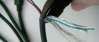
| The power cord is faulty | Visually check the plug and cord for mechanical damage, check the integrity of the cord wires with a multimeter | If faulty, replace the power plug or cord | |
| The switch or speed switch is faulty. The battery in the remote control is low | It is necessary to open the Fan and test the switch with a multimeter. When in the on position, the resistance between the switch contacts should be zero | If the switch is faulty, replace it. If you don’t have it at hand, you can short-circuit the contacts of the switch and turn off the fan by removing the plug from the socket | |
| The fan hums and gets hot when turned on. | The rotor shaft is jammed due to depletion or thickening of the lubricant | Disassemble the fan, wash with solvent and lubricate the bearings | |
| The fan hums and gets hot when turned on. | Break in the starting winding or capacitor. | Turn the impeller by hand, if it rotates, then replace the capacitor or try to find the break point of the starting winding | |
| Broken rotor windings | Visually check the windings for mechanical damage and local darkening, check the integrity of the windings with a multimeter | If a break in the winding cannot be found by external inspection, then it will have to be rewinded, which is not economically feasible. | |
| The thermal fuse against overheating of the electric motor has tripped due to its malfunction | Check the integrity of the thermal fuse with a multimeter. Its resistance should be zero. To check in the absence of the device, you can temporarily short-circuit its terminals | If a broken thermal fuse is detected, replace it with a serviceable one. If the new thermal fuse blows again when the fan is running for a short time, then the electric motor is faulty | |
For reliable operation of the fan, it is recommended to disassemble it and lubricate the bearings with machine oil before each season of operation. But no one does this, including me. Usually, lubrication is done when the blades stop rotating or the fan begins to make a lot of noise.
How to disassemble a floor fan
From what has been said, it is clear: there is nothing to break inside the floor fan. This is a motor and a capacitor. The rest falls on the mechanical part, the gearbox. If there is whistling or noise, try lubricating the gears. How to do this is clear from what has been said. There are a couple of holes in the gearbox housing for these purposes. Solid oil is suitable for plastic parts.
Repairing a floor fan yourself shouldn't be too difficult. Replace the motor with one of suitable weight and size. The main types of breakdowns concern the mechanical part; restoration is carried out using conventional (welding plastic with polyethylene) methods with skilled hands.
How not to connect and why
The first options have a lot of inconveniences, which are not entirely noticeable at first.
For example, let’s say you set up the hood to turn on using a door opening sensor. At the same time, it turns off according to a timer after 5 minutes. It would seem very convenient.
However, it is quite problematic to install such a sensor on an interior door. Not to mention other aspects of operation. For example, what to do if you stay in the toilet longer than the set time.
Open and close the door again? What if there are guests in the kitchen?
In addition, the cables will have to be routed under the tiles, several extra holes will have to be drilled, etc. Simple motion sensors are sensitive to humidity and fail very quickly.
You will have to select expensive models with appropriate IP humidity protection, depending on the zones in the bathroom.
Some people consider the most convenient option to be installing a switch on the hood directly inside the bathroom. However, the PUE prohibits this.
Why this is so, the relevant links and explanations from Rostechnadzor specialists will be given at the end of the article.
Subscribe to the newsletter
An exhaust fan is a device that can increasingly be seen in the homes of our fellow citizens. There are several reasons for this. Firstly, recently, thanks to a significant reduction in the cost of production of such devices, almost everyone can afford such a purchase. Secondly, this electrical appliance is certainly a very useful acquisition for an apartment or a private house.
Electrical circuit of a household fan and its features
The main task of an exhaust fan is to provide forced artificial air circulation in rooms where natural circulation is difficult or insufficient. A striking example of such a room is the bathroom. In apartment buildings, as a rule, this room is located far from the external load-bearing walls, and, therefore, air circulation in them is difficult. If we add to this increased humidity and the mold that arises from it, then it immediately becomes clear that an exhaust fan in the bathroom is not just a tribute to fashion, but a real necessity.
In order to connect the fan, you need to know a few small nuances. You need to understand that the electrical connection diagram of the fan is largely determined by the location of its installation and the presence of design features.
Basic connection diagrams:
1. Connection with built-in switch. The simplest scheme. The device is supplied with 220 V power. The fan is turned on and off using a switch built into the device.
2. Connection via a switch. Using this scheme, the fan is turned on and off using a special switch. As a rule, it is located in front of the entrance to the room. For such a connection, it is necessary to lay 2 cables - one from the junction box to the switch, the second to the device itself.
3. Connecting a fan with a timer. The peculiarity of these devices is that they do not turn off immediately, but after a certain time. This is done through a special time relay, which automatically turns off the device after a predetermined period of time (usually from one minute to half an hour). With this connection, one wire goes to the switch, and two to the device.
4. Connecting a fan with a humidity sensor. The electrical fan control circuit may include a humidity sensor that measures readings in real time and, in accordance with a given program, monitors the operation of the device - it turns it on when humidity rises and turns it off when it reaches optimal values. The device connection diagram is similar to that needed to connect a fan with a timer.
Most fans consist of switching circuits, starting circuits, and electric motor windings. The items on the list concern repairs. Often in household models, a trivial coil is used, wound with a copper core with varnish insulation. Today we will consider how to repair fans with your own hands, the inductance burned out, the wire broke due to the carelessness of the operator. To restore the coil, a good old device is used, despite its simplicity, you cannot get it in the store. With the help of a mechanism, inductors are wound using an electric drive, working with handles.
Industrial fans are different; unlike household fans, they are often centrifugal. The winding of a commutator asynchronous motor cannot be restored at home; it will be difficult to do. Craftsmen repeat the factory production cycle in their native lands.
Bathroom ventilation
In some cases, you can get by with a much simpler solution, for example, for bathroom ventilation. To do this, you can assemble the device according to the diagram shown in Fig. 3. Here the M1 fan is connected to the 230 V power supply circuit in series with an ELI incandescent lamp, which illuminates the bathroom. The fan is powered by a voltage of about 12V DC, which is obtained using a diode rectifier bridge VD1-VD4 and an analogue of a powerful zener diode assembled on transistor VT1, low-power zener diode VD4 and resistor R1.
In this device, the effective supply voltage of the incandescent lamp will be approximately 14 V less than the mains supply voltage, which will have a positive effect on its service life. The KT805BM transistor can be replaced by any of the KT805, KT808, KT819, KT850, KT863, 2SC3746, 2SD1148 series. It may be necessary to install the transistor on a duralumin heat sink.
Fan composition
A typical fan includes:
- AC, DC motor;
- flywheel;
- buttons, relays, contactors;
- automatic regulation circuit.
Optionally there are no elements, the repair diagram looks like this:
- First of all, let's ring the motor windings. Regardless of the design, there are coils inside that give (on the tester screen) a resistance of a few to tens of ohms. Please note: the starting windings of asynchronous motors ring after the capacitor. The obvious point is that ignoring the rule leads to confusion. The capacitor rotates the voltage phase by 90 degrees, helping to create the correct field distribution inside the stator. If the motor is a commutator motor, the windings are connected in series (there is no capacitor). It is wise to ring the motor at the input, since the fault may be hidden in another place. Whether the break is detected or not, remove the brushes and take care of the commutator second. We call the sections one by one. If a malfunction is detected, the maintainability of the cooling fan is assessed by design. It's difficult to do, try to find a new manifold. Needless to say, the drum does not break in asynchronous motors with a squirrel-cage rotor. The current of the “squirrel cage” is relatively small; the copper rolled inside, on the contrary, is thick.
- Secondly, the serviceability of cores, relays, and buttons is assessed. The circuit rings, including the conditions for the thermostat to operate. The implementation method is determined by the design. Simulate heating by using a lighter to heat the sensor. The approach is reasonable in kitchen hoods and other appliances where the temperature is relatively high. The buttons are checked for the passage/interruption of electric current in their respective positions. Do-it-yourself repair of household fans often concerns switching. The buttons are pressed inaccurately and liquid spills. It is necessary to restore the correct functioning of the mechanical part and clean the contacts. Anyone who spilled jam on the TV remote control will understand the situation. The mechanism is disassembled, the contacts are cleaned. It would be useful to recall that the capacitor passes alternating current; in the best case, two operations are performed: they call the element to check for a short circuit (this is a breakdown), apply alternating current power and check the passage of the signal from the winding. We can say with complete confidence whether the capacitor is broken.
Device operation
The mains voltage of 230 V AC is supplied through current-limiting resistor R1 and ballast capacitors C1-C3 to a bridge rectifier made using diodes V01-VD4. Resistor R2 discharges capacitors C1 - SZ after turning off the power. The ripples of the rectified voltage are smoothed out by a large capacitance capacitor C4. The increase in voltage on the plates of this capacitor is limited by series-connected diodes VD5, VD6 and a powerful zener diode VD7. To reliably start the M1 fan, it is advisable to first charge the capacitor C4 to the maximum voltage limited by the supply voltage stabilization circuit, after which the supply voltage can be applied to the fan.
This algorithm of operation of the device is especially appropriate if the fan will be powered at a lower voltage relative to the rated voltage in order to reduce its speed. This is achieved as follows. After supplying the device with supply voltage, capacitor C5 begins to charge through resistor R4. As long as the voltage on its plates is less than 7...9 V, transistor VT1, connected as a micro-power zener diode, is closed.
Transistors VT2-VT4 will also be closed, and no voltage will be supplied to electric fan M1. After 3...5 s, capacitor C5 will charge to a voltage of 7...9 V, transistor VT1 will open, and a current sufficient to open transistor VT2 will flow through it. Together with this transistor, transistors VT3, VT4 will open, connected as a composite transistor with a high base current transfer coefficient. The electric motor will receive a supply voltage almost equal to the voltage on the capacitor plates
C4. If the capacity of ballast capacitors C1-C3 is insufficient to maintain the rated operating current of the fan used, then after the fan starts, the voltage on the plates of C4 will decrease. If the desired supply voltage for fan M1 is less than the reversible avalanche breakdown voltage of the installed instance of transistor VT1, then instead of it you can install a chain of 4 low-power silicon diodes connected in series.
You can also try installing a 100...200 kOhm resistor instead. Resistor R8 creates positive voltage feedback, ensuring VT2-VT4 operates in trigger mode. Diode VD8 discharges capacitor C5 after turning off the power, and C4 discharges through resistor R3. Capacitor C6 reduces the device's sensitivity to interference. If ballast capacitors C1-SZ are replaced with a step-down transformer, these capacitors are not installed, resistor R2 is replaced with a jumper or fuse.
The input of the diode bridge is connected to the secondary winding of the step-down transformer. If in its place we use a transformer of the TPK-6V type with an “open circuit” voltage on the secondary winding of 8.5 V, then the fan will start at a rated operating voltage of about 12 V, and after a smooth decrease in the voltage on the C4 plates it will operate at a reduced supply voltage . When replacing ballast capacitors with a step-down transformer, elements VD5-VD7 are not installed.
How to wind a simple inductance for a fan
Those who have disassembled children's cars know that there is often an inductance inside, an ordinary wire coil. In household fans the picture is similar. Let's talk about ignition devices for electric stoves and other appliances. Inductors can be wound using a special device. You can repair fans yourself without resorting to the help of a specialist.
You will need a board. A half-meter piece of plywood supporting two pairs of posts. The wire will be wound from one, and a new inductor will be assembled on the other. The axis rotates freely between pairs of posts. To automate the process, provide devices for connecting a drive from a screwdriver, drill or other similar device. To manually rewind, use a handle, like the cameramen used in old films.
Before winding the inductor, unwind the old one. Ring the coil in advance so that the repair of duct fans and centrifugal fans does not involve unnecessary work. One end of the coil is the top. Which one is easy to understand by removing the electrical tape, another type of protective coating from the coils. The winding process begins. Clearly, you will need a frame. In the simplest case, you can get by with a wooden spool of sewing thread. When winding, excessive tension and loosening of the wire are unacceptable. Copper is pulled upward with a finger. The drive is turned on, and a second hand can optionally help. The break occurred at the beginning/end, use the wire to wind a new inductance. Otherwise, it is better to buy new components according to the measured length.
Regardless of the type of fan, winding is carried out in rows from the edge and according to the shuttle principle. The turns fit closer to each other, which is controlled by the finger of the hand holding the wire. The ends are brought out exactly as was done with the original coil; in order not to bother your head with details, it is recommended to take a photo with your mobile phone of what the household fan looked like before the repair. Applies to pads, terminals, buttons, relays and motor. Once the winding is finished, secure the ends. The coil is ringing. If the signal does not pass through, then the varnish insulation of the wire is to blame. Removable with an aspirin tablet and a soldering iron, repeat the combination before tinning. Take out the sting and wait for it to warm up.
At the same time, find a piece of electrical tape to wrap around the coil of a household fan. The wire stripped of insulation is ringed; if successful, tin it at both ends. The household fan is ready for use, assemble the electrical connections, put the coil in place, the repair is complete. Let's check whether the device works well from the network. If the engine makes an unpleasant sound, apply lubricant. Are the grinding and squeaking noises gone? The procedure was beneficial for the household fan. Noise is a significant factor when operating home appliances. Connect the fan control unit, the device is ready for operation.
Introduction to Switch Circuit
To increase the productivity of the cooler, it is connected to the electrical network through an autonomous switch.
It is placed on the hood grille or on the wall. This scheme is expensive and labor-intensive, because the total wiring length increases. Methods for connecting a bathroom fan via a switch:
- Using a two-key switch. Lighting and ventilation are activated separately using different keys.
- Using a one-key switch. The key is linked only to the hood.
It is most convenient to place the switch inside the bathroom, however, the PUE standards have a number of restrictions in this regard. As a result, the switch is usually installed in front of the entrance (where the light switch is located).
Installation of the switch step by step:
- Route a two-core cable from the distribution box to the installation point. For this purpose, grooves or cable channels are used (if the renovation in the bathroom has already been done). The ends of the wire are led out into the box and into a niche under the switch.
- Install a socket box. This round plastic box is fixed in the niche with alabaster or starting putty.
- Disassemble the switch and connect the supply wires to the contacts of the operating mechanism. The phase of the house network is connected to the incoming terminal. The phase from the fan is switched to the output terminal. Contact connections must comply with the requirements of the PUE.
- Insert and secure the working part of the switch in the socket box using screws.
- Install the protective cover and switch keys.
Two-gang switch
Two keys make it possible to control the cooler and lighting separately. Ventilation can work separately from lighting until the bathroom is completely ventilated.
When installing a two-button switch in the distribution box, additional connections appear:
- contact between the zero phase of the wire and the zero of the lighting;
- connecting the phase core of the lamp to the wire coming from the second output terminal of the switch.
Switching the switch into two keys is carried out as follows:
- the zero from the ventilation is connected to the neutral network wire;
- the exhaust phase is connected to the phase of the wire connected to one of the output terminals of the switch;
- the power supply wire is connected to the input terminal of the two-key switch;
- The bathroom lighting is switched to the second output terminal.
The only drawback of connecting the cooler via a two-key switch is the elementary forgetfulness of the apartment owners. It happens that people forget to turn off the button responsible for the hood. The engine continues to run, wasting electricity.
Single-key switch (separate from light):
If a switch with one key is selected to control the operation of the exhaust fan, the wires are switched as follows:
- the zero of the ventilation device is connected to the zero of the network wire;
- the phase end from the hood is connected to the line laid from the switch;
- The mains phase is connected to the incoming terminal of the switch.
Household fans
Household fans vary in design and use similar technical solutions. Here is a short list of places where a rotating impeller is useful:
- Refrigerator compressors certainly have forced airflow;
- Repairing the power supply fan is a common problem;
- each asynchronous motor contains a pair of impellers on the shaft for blowing the stator coils;
- no vacuum cleaner is complete without a motor with blades;
- The processor cooler is a smaller copy of a household fan;
- without a heater fan, not a single car interior will warm up properly, and repairing the fan fluid coupling has set some drivers on edge;
- kitchen, toilet and other hoods include a motor and an impeller.
An incomplete list of household appliances that use fans. The computer system unit is excessively noisy - the coolers will need to be lubricated. Carefully peel off the sticker on the fan housing with tweezers, the end of the axis comes out right here. Place a couple of drops on the sliding point and the noise should decrease. Where fans are found, the repair techniques listed above apply. Difference in size, purpose and other details.
Having studied the principles of inductance formation, begin replacing the motor stator coils. It’s a long, tedious process, it’s not recommended to do it, whoever decides to do it, take a photo of the part being repaired, bite out the wiring, wind the turns correctly, and make the reverse connection as needed. It sounds difficult, but it is more difficult to do. Often the coils have no casing. A coil of wires is inexplicably connected to neighboring coils. A household fan looks scary when disassembled. The stator has cuvettes under the wire, where it is difficult to place the turns. Nobody repairs household fan motors.
Ladies generally think that a disassembled fan is unusable, and they throw away the parts that were scattered here and there. Do not leave the opened device unattended.
I got a substandard West SF-1602T fan (with a mechanical timer) made in China, sold by our company Ost-West, almost for free. The approximate cost of a similar one is about $20. The motor windings did not ring. For external wires only gray-blue 0.1k. The external capacitor has one end to the black common and the other to just one terminal from the windings (after opening, see below). Nothing more useful. I removed the rear engine casing (the rotating mechanism and external capacitor are still screwed onto it) and the middle part (plates with coils). The front casing with the rotor remained on the front panel of the fan as there was no need for manipulation. A detailed inspection of the conductor contacts revealed several breaks (as if rotted) of the coil leads under the cambrics. Restored contacts. Added definition: black (general)-red 1.0k. Naturally nothing works. As a result, an almost vandal attempt was made, but the only one, therefore the correct option (already doubtful) was to unsolder all the terminals of the coils. I didn’t think about resoldering the remaining contacts just in case, because it was already too late. I drew the conclusions with an accuracy of 99%. Three conductors came out from almost the same point - I didn’t sign them (well, it was inconvenient), I just sketched the location. After releasing the winding terminals from captivity, everything began to ring. Four windings - 1.0k, 0.2k, 0.1k and 0.7k. Using my sketches and logical calculations (about three conductors from one point), I reconstructed the connection diagram for the windings and capacitor (see figure)
The fan does not turn to the sides
How to fix a floor fan if it stops spinning (turning) from side to side? It's all in the crank
, the mounting screws of which may become loose or unscrewed.
To find out, you will need to disassemble the motor housing. If during operation of the unit the body turns with a delay or a complete stop, then the gears in the gearbox
for engagement. It is also necessary to check the gear switch itself, namely, its movement up and down.
Disassemble the gearbox and remove the main gear. The shaft will also have to be pulled out. Apply lubricant to all moving parts and assemble the gearbox. If the gears are heavily worn, they require replacement, although it is quite difficult to find analogues of broken fan parts. In this case, you will have to assemble the unit without a gearbox and use the cooler in normal mode, when the air masses move in one direction.
Cooler pinout: connecting 3 pin and 4 pin fans
Every home has a lot of computer fans: CPU coolers, video cards and PC power supplies. They can be used to replace burnt ones, or they can be connected directly to the power supply. There can be many applications for this: as a blower in hot weather, ventilating the workplace from smoke during soldering, in electronic toys, and so on.
Fans usually come in standard sizes, with 80mm and 120mm coolers being the most popular today. Their connection is also standardized, so all you need to know is the pinout of the 2, 3 and 4 pin connectors.
On modern motherboards based on the sixth or seventh generation of Intel processors, as a rule, only 4 pin connectors are soldered, and 3 pin connectors are already a thing of the past, so we will see them only in older generations of coolers and fans. As for the location of their installation - on the power supply unit, video adapter or processor, this does not matter at all since the connection is standard and the main thing here is the pinout of the connector.
3 pin cooler connector pinout
The most common type of fan is 3 pin. In addition to the negative and 12 volt wires, a third, “tacho” wire appears here. It sits directly on the sensor leg.
- Black wire - ground (Ground/-12V);
- Red wire - positive (+12V);
- Yellow wire - revolutions (RPM).
4 pin cooler wire pinout
Here the rotation speed can not only be read, but also changed. This is done using an impulse from the motherboard. It is capable of returning information to the tachogenerator in real time (the 3-pin one is incapable of this, since the sensor and controller are on the same power line).
How to connect a 3-pin cooler to a 4-pin
To connect a 3-pin cooler to a 4-pin connector on the motherboard in order to be able to programmatically adjust the speed, use the following diagram:
When a 3-wire fan is directly connected to a 4-pin connector on the motherboard, the fan will always rotate, because the motherboard will not have the ability to control the 3-pin fan and adjust the speed of the cooler.
Fan installation recommendations
Before installing the fan in a prepared place, you need to check its contents. The delivery package must contain instructions that describe in detail the installation procedure and provide recommendations for further operation. The absence of such instructions most often indicates the low quality of the product and its illegal import into the country.
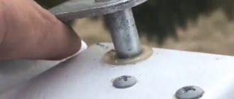
The device can be installed independently without any difficulty. First, remove the front cover of the fan. Silicone or polymer adhesive is applied at the junction of the device to the wall, which is quite sufficient if the weight of the plastic device is insignificant.
Next, the fan is inserted into the hole prepared for installation and pressed against the wall for a short period of time. After this, the front cover is secured in place using self-tapping screws. To protect against insects, a mosquito net is installed in front of the lid.
In order to absorb excess noise, it is recommended to finish the ventilation duct with special noise-absorbing materials. Another method is to install a noise suppressor directly behind the fan.
After installing the fan, you need to connect the electrical wiring to it. Before starting work, the home network must be de-energized. It is not recommended to use twists to connect contacts. A more reliable way is to connect using terminal blocks. The wiring must be with copper conductors. If you do not plan to replace the tiles in the bathroom, the wires are laid in plastic boxes. The final installation and fastening of the fan is carried out only after it is connected to the electrical network.
Fan installation procedure
As in any construction work, the ventilation system first needs to be designed. It is better to do this at the very beginning of the bathroom renovation, in order to be able to hide all communications in the walls and under the ceiling.
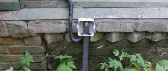
If we are talking about a bathroom in an apartment where there is already a hole in the wall into a common ventilation duct, you just need to turn natural ventilation into forced ventilation. To do this, it is enough to decide on the fan model and the diagram of its connection to electricity.
The exception is apartments in which the ventilation shaft is adjacent to only one of the rooms of a separate bathroom - a duct will be required there
In a private house, you usually have to build a system from scratch, leading the ventilation pipe to the street through the roof, or less often through the wall. In this case, it is necessary not only to think through everything, but also to draw up a plan diagram, according to which it will be convenient to count the necessary materials and carry out installation.
It is worth checking the presence of natural draft in the existing shaft, and if it is completely absent, contact the housing office for cleaning. For effective air exchange, it is better to place the hood opposite the door or flow valve, if there is one.
The next stage is purchasing everything you need. It’s worth purchasing in advance even what will be installed at the very end of the repair, because another fan model may not connect to the wires already connected.
Having figured out how to connect the purchased fan and selected a ventilation scheme, you can begin renovating the bathroom.
During the decorative finishing of walls and ceilings, wires are laid in corrugated insulating tubes, if necessary, a ventilation duct is constructed and the size of the hole for the fan is adjusted. Connecting the wiring and installing switches is also carried out at this stage.
An alternative option, available only in a private house, is to install a duct fan. When installing it, only a special plate is screwed to the wall, and the main body with the motor is snapped into the side fasteners
The fan itself is installed after finishing is completed. The installation procedure is as follows:
- Make sure that the wires leading out to the fan are de-energized.
- Remove the front panel, insert the housing into the hole and mark the mounting locations on the tile with a marker.
- Drill holes using a drill with a ceramic drill, and hammer dowels into them. This step can be neglected completely or only part of the provided fasteners can be used. Plastic fans weigh little, usually liquid nails or polymer glue are enough to fix them.
- Even when mounted with self-tapping screws, the perimeter of the fan housing must be coated with silicone or other polymer to absorb vibrations and prevent noise.
- Insert the housing into the hole, check the level (for models with a square front) and press firmly until the sealant sets.
- Connect the wires to the terminals of the device and secure it so that there are no bare areas left.
- Turn on ventilation, check operation in all provided modes.
- Install the front panel.
This procedure is universal and is suitable for overhead fans of any model. It also does not matter whether the fan is installed in the wall or in the ceiling - only the installation of duct models differs.
Some models have a control board with the ability to set the operating mode for the bathroom or toilet, as well as set the timer
If the fan is designed with a timer, hygrometer, mode switch or other equipment, do not forget to set it up before the decorative panel is put on.
Often, from the factory, the timer adjustment screw is turned out to the minimum - select the required operating time experimentally.
There may also be a mode switch, which looks like 3 or 4 metal pins with a removable jumper on two of them.
In the “toilet” mode, the fan starts immediately, simultaneously with the light turning on, and runs for the time set by the timer. In the “bathroom” mode, the start signal is to turn off the lights, so noise and drafts will not disturb you in the shower.
After adjustment and configuration, do not forget to close the holes on the cover to protect the board from moisture, if this is provided for by the design
The built-in hygrometer can be set to a certain humidity level at which the fan will start.
Is it possible to install two fans in series?
This question can be formulated in different ways. If you cut the connectors on the wires and twist them in series, this will halve the voltage of each and, accordingly, the rotation speed. You can connect this way if you know what you are doing.
It is also possible to connect fan housings together along the axis of rotation to increase air flow. But the increase in productivity in this case is doubtful. In theory, performance increases by 20-30% with 2 connected in series. In practice, I recommend buying a more powerful fan or connecting existing ones in parallel. This is easy, given the many adapters in stores.
How many fans can be installed on one connector?
The 4-pin Molex ATX12V connector (also called P4 power connector), which is both a plug and a socket, allows you to connect an unlimited number of devices in parallel. The power of such devices is low. Therefore, if you wish, you can install all case fans on one connector.
Double-sided Molex
Splitters are also available for sale. For example, from a four-pin Molex to 4 fans with a 3-pin connector. Pay attention to the color: white - 12 V, black - 5 V.
3-pin and 4-pin connectors have limitations. If you don’t do some DIY work, but use factory connectors, one connector on the motherboard allows you to connect one fan. Using a splitter you can increase the number, but I would not put more than two turntables on one slot.
Stages of installing a ventilation system
After the preparatory work, it is recommended to study the instructions that come with the fan.
Here you can study in detail the installation process of a specific device. In addition, the insert contains requirements for the operation of the unit. Products that do not have these instructions may be counterfeit or illegally distributed.
The problem with such devices may lie in their poor quality. And this will cause a lot of problems and troubles during use in the bathroom.
Installing the fan takes up to 15 minutes of free time.
The device must be installed following the following sequence:
- Remove the cover from the front side of the device.
- A layer of polymer adhesive should be applied to the place where the device will be installed to the wall. Alternatively, liquid nails or other silicone material can be used. This fastening is sufficient to ensure that the housing does not fall off the wall over time. This is due to the low weight of units for domestic purposes.
- The next step is to install the product in the shaft. This is done so that the working element is completely immersed in the channel. Press the device firmly for a few minutes to ensure maximum adhesion.
- Installation of mosquito net. This is necessary to prevent insects from entering the room and causing discomfort. In addition, such a mesh performs a decorative function.
- Next, you need to secure the front side of the cover with self-tapping screws. They come complete with the product, like other accessories.
- Connection to the power supply network.
If there is a switch on the case, then you don’t have to worry about moving it to another zone. But sometimes this arrangement is not convenient. Therefore, you can put it on the wall or even take care of a two-key product that will work to turn on the light and ventilation.
As you can see, the installation is not difficult. It all comes down to laying the cable, connecting the device to the network and securing it in the ventilation shaft. But if you had to face any difficulties, then you should contact a professional.
During operation, you may encounter the problem of increased noise, as discussed above. If you do not want to dismantle and change the device in the bathroom, then you can always install so-called noise suppressors, which are installed directly behind the unit. As an alternative, sound-absorbing materials can be used.
Connecting the cooler to the power supply or battery
To connect to the power supply, use standard connectors, but if you need to change the number of revolutions (speed), you just need to reduce the voltage supplied to the cooler, and this is done very simply by rearranging the wires on the socket:
This way you can connect any fan, and the lower the voltage, the lower the speed, and therefore the quieter its operation. If the computer does not get very hot, but is very noisy, you can use this method.
To power it from batteries or rechargeable batteries, simply connect the plus to the red wire and the minus to the black wire of the cooler. It starts to rotate at 3 volts, the maximum speed will be somewhere around 15. You cannot increase the voltage any more - the motor windings will burn out from overheating. The current consumption will be approximately 50-100 milliamps.