Correct connection of the welding inverter prevents emergency situations and ensures the convenience of performing work operations. The instructions in the accompanying documentation provide a general procedure. To avoid problems, you should carefully study the rules for handling equipment, consider the use of extension cords and autonomous power supplies.
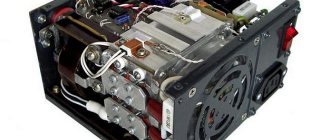
Inverter welding machine.
Welding inverter and its operating principle
To connect metal parts, high heating of the working area is used. The molten parts, after lowering the temperature, form a strong seam with a uniform internal structure. This mount is different:
- durability;
- strength;
- resistance to mechanical and other external influences.
The melt zone (welding pool) is created using an electric arc. An inverter is a device that generates the output signal necessary to ignite it. Equipment in this category is connected to a 220 V or 380 V network. After rectification, the current is converted to alternating current.
Increasing the frequency allows you to reduce the size and weight of the transformer. The final stage is the reverse conversion to high direct current (20-260 A) with a corresponding reduction in voltage.
A typical household inverter device is designed to connect to a standard 220V network. The equipment is equipped with:
- digital indicator of operating parameters;
- current regulator;
- LED overheat alarm.
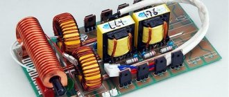
Principle of operation.
The automation unit provides:
- “hot” (quick) start;
- correction of the output signal to prevent sticking of the electrodes.
Connecting cables are supplied as standard. Protective devices and technological accessories along with consumables are purchased separately.
Equipment check
Before connecting the power source, the integrity of the housing and regulator handles is checked by external inspection. Organize the workplace as follows:
- clear a flat area (metal table);
- set a minimum distance of 2 m from the device to the walls;
- connect the protective grounding circuit;
- eliminate explosive (flammable) objects.
Effective ventilation of the room during welding is recommended to prevent harm to health from the polluted atmosphere. You need to prepare a mask, leggings, and electrodes in advance. Free passage of unauthorized people into the work area should be prevented. Remove foreign objects that interfere with individual operations.
We recommend reading Welding inverter Resanta SAI-250
Correct connection
Proper connection ensures the welder productive and safe work.
Connecting wires to a welding machine requires compliance with a number of rules:
- there must be a terminal at the end, crimped or soldered;
- The wire cross-section must correspond to the maximum operating current of the device plus a margin of 20%
- You should carefully monitor the polarity of the connection and observe it;
- The cable must lie freely in the work area, without tension or loops.
How to connect a welding machine if there is not enough wire to the welding zone? You can increase its length.
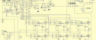
Electrical connection diagram
Welding of thick (16-17 mm) sheets of metal is performed with 6 mm electrodes at a set output current of 240±20A. In this mode, the load on the power supply increases, which is accompanied by a voltage drop. If the corresponding value is less than the permissible operating parameters, the automation will turn off the inverter.
Another problem is limited wiring options. Aluminum (copper) conductors of the household network are designed for 10 (16) A. It is recommended to check the compliance of the power consumption of the device with the operating parameters of the circuit breakers and fuses.
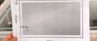
The figure shows a connection diagram for a welding machine, which minimizes the influence of powerful equipment on other equipment:
Welding machine connection diagram.
It is recommended to straighten the network cable. A bent conductor creates inductive reactance, which increases the load on the power supply. The areas that form the coils overheat until the protective shell is destroyed.
Step-by-step instructions for connecting a welding machine
Figure 2. Sequence diagram for connecting the welding machine.
After you have checked the integrity of the unit and all related components, and also established the voltage compliance, you can proceed directly to connecting your welding machine. For this you will need:
When connecting the device, you can refer to the diagram in Fig. 2.
The connection is made in a certain sequence, namely:
- First, a plug is prepared with the appropriate thermal throughput parameters.
- Select a socket with a circuit breaker or fuse.
- The return cable is connected to the terminal.
- The holder cable is connected to the electrode fragment using a clamp.
After you have done all this, the welding machine can be connected to the network. Most models have fairly short wires, so connecting them often requires the use of an extension cord. The extension cord must have a wire of sufficient cross-section. The reliability and safety of operation depends on the number of intermediate connections. The fewer there are, the better.
Expert opinion
It-Technology, Electrical power and electronics specialist
Ask questions to the “Specialist for modernization of energy generation systems”
Wires for a welding inverter: how to properly connect the cables to the device and the 220V network - Consumables and components for The KRTP cable with flexible stranded copper cores is intended for mobile devices that perform manual welding. Ask, I'm in touch!
Other DIY connection methods
In an older home, the protective devices, wiring, and outlets are not designed to withstand heavy loads. High current causes a short circuit. Voltage surges can damage household appliances in your own apartment and those of your neighbors. To eliminate connection problems, you should consider solving this and other typical problems.
Using a current generator
To organize autonomous power supply, a compact power plant with a gasoline (diesel) engine is used. Such a generator can be purchased or rented for the duration of work operations. When choosing equipment, check:
- power;
- voltage stabilization;
- compliance with working conditions.
Calculation of output parameters for the considered example with welding of thick sheets:
- current – 240 A;
- voltage – 40 V;
- power – 9600 W = 240*40.
A 10 kW generator in this mode will operate at the limit of its capabilities. This reduces the life of functional units and increases the risk of overheating and breakdowns. To eliminate negative factors, choose a source with a power reserve of 25±5%.
Using extension cords
The length of the serial network cable does not exceed 4 m. To expand the working area, a “carrying” is used. If the welding current is not more than 150 A, a 20-meter extension cord with a conductor cross-sectional area of 2.5 mm square is suitable. The power line is installed without bends to eliminate the parasitic influence of inductive reactance.
We recommend reading: How to choose electrodes for an inverter
Selecting cable parameters
To transmit high current, a conductor with a large cross-section in a thick protective sheath is used. Fixed terminals are used to connect to the welding machine. When choosing a cable, pay attention to the following details:
- copper conductor provides low resistivity;
- the use of aluminum reduces the cost of the product;
- the multi-core design maintains the integrity of the core after repeated twisting/straightening cycles;
- The shell with special additives is resistant to high and low temperatures.
Important parameters of cable products are determined by special markings in the name:
- HL (T) – the product is intended for use in cold climates down to -60°C (tropical);
- N – non-combustible insulation;
- KG – flexible cable;
- PES is a modification for a semi-automatic device.
A suitable cross section is selected taking into account the current strength (maximum):
- 6 mm sq. – 100 A;
- 10 – 120;
- 25 – 200;
- 35 – 290;
- 50 – 300.
| Conductor cross-sectional area, mm sq. | |||
| Current (I), A | Cable length, m | ||
| 0-15 | 15-30 | 30-60 | |
| 30-100 | 25 | 25 | 50 |
| 100-200 | 35 | 50 | 70 |
| 200-300 | 50 | 70 | 90 |
For an accurate calculation, use the formula D=S/K, where:
- D – permissible length;
- C – cross-sectional area;
- K – correction factor (K=I/100).
When checking the package, in addition to the cable, you should select the correct holder and clamp for connecting the ground.
When choosing a cable, you need to pay attention to a number of details.
Selecting extension cord parameters
Often the power cable included with the inverter is too short and does not provide a welding connection so that it is located near the structures being connected. Therefore, welders are forced to use extension cables or carriers. They differ from similar household devices only in the increased power of the conductors.
From a technical point of view, an extension cord is nothing more than an additional section of the circuit from the inverter apparatus to the current source. Therefore, the well-known Ohm's law is quite suitable for calculations. With the same power of different connected consumers, the cross-section of the conductor directly depends on the length of the portable cable. The material should be metals with minimal resistivity.
Therefore, all modern conductors are made of copper. The insulation does not affect the electrical properties of the cable in any way, but during operation it is subjected to various mechanical loads. Its thickness should be as high as possible, in this case the cable will last much longer.
The choice of cross-section is made depending on the value of the welding current. The cable length and voltage are taken as the initial data for calculations. You should take into account the possible voltage drop in this area, which can cause overloads in the home network. It is mandatory to create a power reserve of at least 10%, eliminating the possibility of overheating of the conductors.
Basics of using a welding inverter
At the preparation stage, the features of the technological process are clarified. A 2.5 mm electrode is used at a current of 90±10A for welding workpieces of the following thickness (mm):
- cast iron – 3 or more;
- stainless steel – 1.5;
- “soft” steel grades - from 2 to 5.
To find out how to connect a welding inverter under other initial conditions, use the reference data. Based on the results of the test seam, the operating parameters are adjusted.
As the current increases:
- the seam is deeper;
- you can move the electrode faster without compromising the reliability of the connection.
We recommend reading: How to repair a welding inverter yourself
Before welding, thoroughly clean the surfaces. Remove rust, grease, paint. To create a high-quality seam, both workpieces are heated with equal intensity.
Distribute the melt evenly on the sides. The reduction in electrode length and the corresponding change in arc parameters should be taken into account.
Training improves work skills. For beginners, markings highlight the connection line to improve visibility. The electrode is moved at an angle of 30-60°. Maintain a constant arc length of 2-3 mm.
Characteristics of the welding inverter Resanta SAI 190
To operate the manual arc welding machine SAI 190, it is recommended to purchase electrodes with a diameter of up to 5 mm. The maximum welding current is 190 amperes (technical data). However, practitioners note the fact that the figures are overestimated. It is almost impossible to achieve such values in practice, and they are somewhat lower.
The inverter is small in size and light in weight – no more than 5 kg. This is convenient if you have to frequently transport equipment. For example, take it with you to the dacha and pick it up when you return home. Wide operating temperature range: from -10 to +40 degrees Celsius, which is very practical for our climate zone.
It is worth noting the very modest configuration of the welding inverter. The price includes welding and power supply cables. All other equipment will have to be purchased. On the other hand, the equipment comes with a two-year warranty, which gives you confidence in its reliability.
Connection with different polarity
Electrons move in a conductor from minus to plus. Therefore, the seam parameters depend on how to connect the clamp and ground cables, taking into account polarity.
The direct method is to connect the minus to the electrode. In this case, the heating of the workpiece improves. The technology is used to join thick sheets.
Reverse polarity is used to perform accurate work operations. The comparatively lower temperature effect prevents through-burning of thin products.
Precautionary measures
To safely reproduce technological operations, the following rules apply:
- check the integrity of the device and insulation;
- measure voltage (in idle mode U=0);
- check the compliance of the power supply network with the connected load;
- remove foreign objects from the work area;
- install protective grounding;
- create good ventilation and illumination;
- use shoes with rubber soles (mat, wooden flooring) to prevent electric shock;
- Use protective clothing, gaiters, and a mask.
Before creating a connection, check the voltage sag in the network by test welding at maximum current. It is recommended to place sand or other means to quickly extinguish a fire at a short distance from the work area.