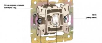
How to connect the contact block correctly?
This block is installed on the top of the contactor, where there are special connectors with hooks.
The working circuit has two pairs of closed contacts, as well as two pairs of open connectors.
Normally open contact (NO) – when not working, it is always in the open position (pair 1-2). Therefore, for current to pass through it, it must be closed.
Normal closed contact (NC) - its non-working position is the closure of the connectors (pair 3-4). In this situation, when the contact opens, there will be no current through the magnetic starter.
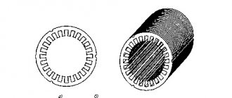
PM is a structure consisting of two basic fragments:
- top;
- lower
The upper part is a moving contact system, an arc-extinguishing chamber and a moving element of an electric magnet, connected to the connectors by the moving area of the mechanism.
The lower part consists of a winding, a return spring and a second fragment of the magnet body.
The role of the spring is to return the initial position of the upper region of the device, thus, in the absence of contact of the magnetic connector, there is no current in the winding.
Design and principle of operation of the contactor
Based on the name, this is a group of contacts designed to connect electrical lines. The main application is a modular contactor that switches power lines. If in a regular switch (even an automatic protective one), closing and opening occurs manually, AC contactors are controlled remotely.
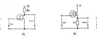
Let's consider the circuit of a simple contactor, without interlocks and protective modules.
For those who are more or less familiar with electrical engineering, it is not difficult to understand the principle of operation. The basis of the power group is the contacts indicated in the diagram by the letters “L” and “T”. Depending on the design, the system may simultaneously include one, two, or more pairs of contacts. In order for the connecting conductor strip to press against the fixed contacts, force is required. In conventional switches, this is a mechanical device driven by the operator. Our circuit is triggered by an electromagnet. When control voltage is applied to coil A1-A2, the solenoid is retracted and the power (operating) contacts are closed.
To ensure reliable and safe opening, a return spring is provided.
After removing power from the control winding, the return spring instantly removes the contact strip from the power terminals.
What is inside
Despite the apparent complexity and cumbersomeness of the design, the element base is simple:
- contact group made of copper (brass) alloys, designed for a certain resource;
- “T” shaped contact strip directly connected to the electromagnet solenoid;
- an electromagnet coil made for a specific contactor model;
- dielectric housing, which performs not only protective, but also load-bearing functions;
- arc extinguishing elements that are installed in the switching mechanisms of electrical installations with high current consumption.
In fact, the design is not much different from a conventional relay. There are also normally closed, normally open, and switching circuits (in which both types of contact groups are present). At the same time, according to the technical requirements of GOST, the modular contactor must have only one rest position (the state of the contact group in the absence of external control pressure).
When mechanical action is applied to a conductive strip (or group of strips), one or more contact pairs are closed (opened).
Thus, with the help of direct or remote influence, it is possible to control the power of electrical installations or power lines.
Features of a single-phase device
A standard device operating in an alternating current electrical circuit with a frequency of about 50−60 Hz and a voltage of up to 400 V is considered a single-phase contactor. Its design consists of an electromagnetic coil, a spring, an armature and two pairs of normally open contacts.
When voltage appears, a current begins to pass through the coil, generating an electromagnetic field. The force created in it contributes to the attraction of the armature and the closing contacts. Parallel to the movement of the armature, the indicator begins to move, giving a signal at the moment of connecting or opening the contacts.
Once the single-phase voltage is removed, the magnetic field is neutralized. The disconnected contacts return to their initial position due to the action of the spring.
During the installation process, a single-phase MK is installed on a DIN rail in such a way that current passes through it. To connect, use a button and a relay.
Activating the Start button starts the contactor, the closing contacts cause the motor to rotate. Pressing the Stop button breaks the electrical circuit and the engine stops rotating.
As the current in the stator increases, the elements heat up. The presence of a thermal relay allows them to be protected from dangerous overheating. When heated to a critical temperature, the circuit opens and the device turns off.
In this case, you should use a special locking key to prevent erroneous activation. If the arc extinguishing elements are removed during installation, you should avoid turning on the device. This may cause a short circuit in the circuit.
Operating principle
When voltage is applied to the control coil, the armature, under the influence of electromagnetic forces, is attracted to the stationary part of the core, overcoming the force of the spring and selecting an air gap. In this case, the moving contacts of the contactor are pressed against the stationary ones, ensuring the connection of the power electrical circuit.
When the control coil circuit is disconnected, the armature, under the influence of the spring, returns to its original position. In this case, the contacts open. The special design of the arc-extinguishing chambers in which the contacts are placed contributes to the rapid attenuation of the electric arc resulting from a break in the electrical load circuit.
Design and principle of operation
A standard contactor design includes several basic parts. The device consists of a housing (1), a control coil output terminal (2), a power contact terminal (3), a fixed magnetic core (4), a moving part - a core (5), a control coil (6), a short-circuited magnetic circuit ring (7), fixed and moving contacts (8 and 9), on-off indicator lever (10).
The coil is the main element that creates the magnetic current. If it is also used as a throttle, then with its help a driving force is generated that ensures the operation of the devices. The tension of the contacts is fixed using a contact spring. During docking, the moving and fixed contacts are connected to each other. They are constantly in motion and perform certain actions. Fixed contacts are fixed to the body, and movable contacts are connected to the core.
The contactor works as follows:
- After applying voltage to the control coil, the armature is attracted to the core. As a result, the contact group closes or opens, in accordance with the initial position of a particular contact.
- After turning off the power, all actions occur in the reverse order. The electric arc that occurs at the moment of opening is extinguished using an arc extinguishing system.
- After the voltage supply is stopped, the electromagnetic field disappears and ceases to hold the armature or core.
- The return spring moves the contacts to their original position, completely opening the circuit. Thus, the modular contactor performs its main work during periods of supply and shutdown of voltage.
Main types of modular contactors
Actuator. This device provides for the presence of auxiliary contacts, a special relay, and an autostart system, while the automatic system can also be divided into reversible, non-reversible, and with and without switching of windings.
Magnetic switch. The device is a three-pole contactor; it is equipped with two relays that serve for reliable protection.
Intermediate relay - this device has low power; it allows you to increase the number of contacts in circuits in which the current is relatively weak.
Manufacturers label their products differently, each brand has its own designation structure
When choosing a model, pay attention to its purpose; for example, MKs produced by ABB are ideal for automating equipment systems in buildings
Contactors with serial designations MF or MT are used for power or control circuits, and when a device for remote control is required, it is better to choose KME devices.
Using three-switch circuits
Article rating:. The switching mechanism in pass-through switches is located in the center of the contacts.
The device provides comfortable light control and safe movement of people. With such a power supply arrangement, identical devices will not work. The more devices are involved in the implementation of the control system, the more complex the construction scheme becomes.
Useful video Switch from three places - a modern solution for light control Electricity and other resources are rising in price, and the emergence of modern technologies allows for significant savings.
Many novice, non-professional electricians confuse these concepts and try to organize a pass-through circuit on a three-key switch. Take a screwdriver with a phase detector or a multimeter, and look for where the plus is and where the minus is. We are talking about long corridors, stairs, basements.
Let's say one of them will be located near the bed, the second at the exit of the room, and the third near the desktop. The appearance of the duplicating devices is almost the same as that of a single-key device. Three-key pass-through switch Such a switch is not actually a pass-through switch, and cannot be used in a lighting circuit with several switching points. If you need a diagram for connecting a pass-through switch from two places, see it in this article.
During installation, the switches are installed so that when turned off the keys are in the same direction. It contains both an input and an output in the amount of 2. Meanwhile, the cross switch has a completely different circuit and switching mechanism. According to the wiring rules, all wires in such an electrical circuit must be located at a distance of 15 cm from the ceiling. The lighting device is turned on when 2 switches are in the same position.
Similar fastening of the remaining outputs. And the other two are installed on some courtyard buildings, a garage, a shed, upon reaching which you can turn off the lighting. In everyday life, not only step-down transformers are used, but also step-up transformers. The apartment buildings have three floors.
Let's say one of them will be located near the bed, the second at the exit of the room, and the third near the desktop. Connecting a line to a wire with the wrong cross-section. Pass-through switches from 5 places without junction boxes. tokzamer.ru
Purpose of contactors
These devices can be divided according to their main characteristics, although the scope of application is virtually unlimited.
Types of contactors by purpose
- Remote switching devices (switching off, switching). When operating a complex of electrical installations, it becomes necessary to implement a certain power supply algorithm. Manual control: button, switch. The operator gives a signal at the right moment, the AC contactors are activated, switching the power according to a given operating pattern. For example, by pressing one button you can start an entire plant: conveyor, machines, lighting, ventilation system. By connecting many contactors in a certain way, it is possible to automate the power system on the control circuit (in this case, starting commands are given manually). In automatic mode, the command is given using an electronic circuit. The program controls production cycles at the right time, starting and stopping electrical installations. At the same time, any linear contactor can be equipped with a protection function: for example, a limit switch or thermal relay. When certain emergency conditions are created, the power to the coil is cut off and the operating contacts are opened.
- Switching on a powerful electrical installation using a low-current line, or again with a button (switch).
A typical example is an electric motor starter. It would seem, what does a modular contactor have to do with it: what is it for if you can use a button or a switch? Indeed, power can be supplied to the electrical installation directly using the contacts of the button. However, for a reliable connection of a powerful consumer, the contact group and the closing mechanism must be massive, and great force must be applied when turning on. The same force must be used to de-energize. This is not always convenient, especially in an emergency. Therefore, the device with which the operator directly works is compact, it is designed for low current (the consumption of the contactor coil is small), and a small force is required to activate it, especially on the off button. And the linear contactor itself can be quite large, and it operates instantly. Another reason why power separation of control and power lines is used is the high frequency of on and off cycles. For example, electric vehicles. The driver presses the accelerator pedal up to a thousand times per shift. If you equip the lever itself with power contacts, it will be inconvenient to use. Therefore, the pedal only supplies a weak current to the coil, and the line contactor starts the powerful electric motor.
Many of you, being near the driver's cabin, have heard regular loud clicks when pressing the pedal. This is exactly how a line contactor works.
Various drive types
Electromagnetic is the main type and the most common. We discussed the principle of its operation in detail at the beginning of the article.
Unless you can focus on the holding mechanism of the working coil. Most push-button (magnetic) starters do not have a locking button
That is, after the operator removes his finger, the power to the electromagnet should disappear. The design of most starters takes this point into account. There is a contact group on the end plate pusher that closes the solenoid circuit. While the entire electrical installation is working, there is power on the coil. If the voltage drops for a short time (emergency situation, or the disconnect button is pressed), all circuits are broken and the switch is turned on again. This adds safety during operation of the mechanism. After an uncontrolled power restoration, the electrical installation will not start until the operator decides to turn it on. the working day is over, the switch remains closed (the machine is not working, everyone has forgotten about the accident); power on the line is restored, machines, heating elements, etc. begin to work in the deserted workshop.
The use of contactors eliminates such situations.
We've sorted out the electromagnetic thrust. Besides this, there are other ways to set a contact group in motion. Pneumatic devices allow you to close powerful contacts without the use of electromagnetic drives.
The operating principle is the same, only the high pressure pulse acts as a control command. Such devices are widely used on railway locomotives, or other installations where pneumatics are present.
Contactor connection
Before connecting, it is sometimes useful to make sure the product is working. To make it clear how to check the contactor, it is necessary to find out what algorithm is used to carry out this procedure:
- assessment of condition by visual inspection;
- setting up the magnetic system;
- checking the integrity and insulation resistance of current-carrying elements;
- adjustment of the contact system.
Ease of movement can be checked using a short circuit. If a strong hum is noted, the screws that hold the core and armature are tightened. If frozen metal particles or deposits are found on the contacts, it is necessary to remove them with a file, without using any lubricant.
Before starting the process, it is strongly recommended that you familiarize yourself with the detailed connection diagram.
As a rule, you should first route the incoming cables and secure them with special fasteners. Then the output wires are connected and secured. A thermal relay or a start button may be located in front of the contactor (a rectifier will be required if the button station will use alternating current).
The contact and connection diagram does not depend on the manufacturer and standard sizes of the product. Special marking of contacts allows you to understand the purpose of each of them. You can get a lot of information from the network on how to connect a contactor, but it is not recommended to do such work yourself without having the necessary skills and knowledge.
A large assortment of modular devices designed to work with electrical wiring, as well as other analogues for working with various motor starters, is available on the official website. Photographic materials will help you get an idea of what the contactor looks like, and the characteristics and descriptions will allow you to quickly select the appropriate model.
Modular contactor connection diagram.
Below is a wiring diagram for the modular contactor. The main point of the connection is to supply power to the coil (contacts A1-A2), which will open or close the power contacts NO and NC of the contactor.
Connection to 220 V network
Connecting a magnetic starter to a 220 V network is the simplest, so it makes sense to start familiarizing yourself with these circuits, of which there may be several.
A voltage of 220 V is supplied directly to the coil of the magnetic starter, which are designated as A1 and A2, which are located in the upper part of the housing, as can be seen from the photo.
Connecting a contactor with a 220 V coil
When a regular 220 V plug with a wire is connected to these contacts, the device will start working after the plug is plugged into a 220 V socket.
We recommend reading: Pinout of different types of USB connectors: pinout of micro and mini usb, pinout features
Using power contacts, it is permissible to turn on/off an electrical circuit for any voltage, as long as it does not exceed the permissible parameters indicated in the product passport. For example, you can apply battery voltage (12 V) to the contacts, with which a load with an operating voltage of 12 V will be controlled.
It should be noted that it does not matter which contacts the single-phase control voltage is supplied to, in the form of “zero” and “phase”. In this case, the wires from contacts A1 and A2 can be swapped, which will not affect the operation of the entire device. It is quite natural that such a connection circuit is used extremely rarely, since it requires direct voltage supply to the coil of the magnetic starter
In this case, there are many options for switching on, using a time relay or a twilight sensor, connecting, for example, street lighting to power contacts. The main thing is that the “phase” and “zero” are nearby
It is quite natural that such a switching circuit is used extremely rarely, since it requires direct voltage supply to the coil of the magnetic starter. In this case, there are many options for switching on, using a time relay or a twilight sensor, connecting, for example, street lighting to power contacts. The main thing is that the “phase” and “zero” are nearby.
380 V connection
Connecting a contactor operating with 380 volt networks is almost no different from the previous circuit. The only difference lies in the supply of electricity to the coil. In the original version, this problem was solved by using phase (L3) and zero (N), and in the 3-phase version, the connection is made to two phases L2 and L3.
The completed diagram clearly shows the power supply to the starter coil (KM1), connected to phases L2 and L3. The first is routed through a thermal relay (P), and the second through a push-button element for starting (SB2) and braking (SB1) and an auxiliary contact (KM 1), connected to each other in a series circuit.
The action of this scheme is carried out in a certain sequence. When the starting push-button device is pressed, electricity from one of the phases approaches the coil. Under the influence of a field with magnetic properties, the core is retracted, which causes the entire contact group to short-circuit to the connected load. The current voltage, in this case, is 380 V. The released START button does not interrupt the power supply to the circuit, which is provided by an additional movable contact closed at the moment the core is retracted.
In the event of an emergency, the thermal relay is activated. A phase break occurs, the power is turned off and the coil is de-energized. Under the action of springs, the magnetic core returns to its original position. After opening the contacts, the voltage in the emergency area is removed.
How to connect a contactor
When connecting a contactor, you immediately need to decide on the mechanism that it will turn on. This could be a motor, pump, fan, heating elements, compressors, etc. The main feature of a contactor that distinguishes it from a machine is the absence of any protection. Therefore, when thinking through the circuits for switching on electrical equipment through a contactor, it is necessary to take into account the current-limiting and heating elements. To limit and shut down equipment in case of short circuits and loads many times higher than the rated load, fuses and circuit breakers are used. Thermal relays are used to prevent long-term slightly exceeding the rated currents of operating equipment.
In order to correctly connect a contactor to a circuit, you need to clearly understand which of the contacts are power and which of them are auxiliary, that is, block contacts. You also need to look at the ratings of the switching coil. The voltage, its type and magnitude, as well as the currents that flow through it for normal operation must be indicated there. During operation, power contacts may burn, so they must be inspected and cleaned regularly.
How to connect a modular contactor
A modular contactor is a type of conventional switching devices of the same type, only they are mainly used for switching switchboards on and off remotely. That is, turning it on, power is supplied to a group of machines, each of which is responsible for its own specific circuit. It is installed on a DIN rail. Can switch both direct and alternating current circuits.
Connecting a contactor via a button
To connect the contactor via a button, you need to study the attached diagram below. It is designed to start a load, in this case a motor, from a contactor whose coil is designed for 220 Volts alternating voltage. Depending on the voltage, it is worth considering its power supply. Therefore, when purchasing and selecting a contactor, it is worth taking this nuance into account. Since if the electromagnet is designed for constant voltage, then such a source will be needed.
When you press the start button, the contactor electromagnet coil will receive power and it will turn on. The power contacts will close, thereby supplying voltage to the asynchronous motor. The block contact of contactor K1, which is connected in parallel to the stop button, will also close. It is called by electricians a self-retaining contact, since it is this that supplies power to the switching coil after the start button is released. When you press the stop button, the power from the electromagnet is turned off, the power elements of the contactor break the circuit and the engine turns off.
Connecting a contactor with a thermal relay
The thermal relay is designed to prevent prolonged minor current overloads during operation of electrical equipment, because overheating negatively affects the condition of the insulation. Frequent excesses of temperature and current will lead to its destruction, and therefore to a short circuit and failure of an expensive actuator.
When the current in the stator circuit of the electric motor increases, the elements of the thermal relay KK will heat up. When the set temperature, which can be adjusted, is reached, the thermal relay will operate and its contacts will break the circuit of the electromagnet coil of the KM contactor.
For safety reasons, you must remember that work in the contactor circuit must be carried out when it is completely de-energized. In this case, the power supply must be locked with a key or prohibiting sign from unauthorized or erroneous activation. And also you cannot turn on this device with the arc chutes removed, this will lead to a short circuit.
Connection diagrams for consumers and modular contactors
In accordance with the type of electrical equipment used, in each case an individual connection diagram for the modular contactor is provided. The most widespread is the standard version, which uses only one device, as well as reversible circuits and with the connection of single-phase consumers. Each of them should be considered in more detail.
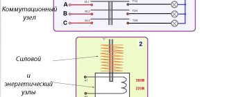
The most popular scheme is connecting a three-phase electric motor through a modular contactor KM (Fig. 1). The usual START and STOP buttons are used for control. Overload protection is provided using a thermal relay. In case of short circuits, the electrical circuit is equipped with an automatic switch.
Another circuit is reversible (Fig. 2), used when connecting a modular contactor to an electric motor so that the reverse function appears. It is constantly needed in various lifting mechanisms, machines and other equipment. In this case, another switching device is connected. It is involved in changing the locations of two phases, which also leads to a change in the direction of rotation of the shaft. This circuit is also supplemented with protective equipment - a thermal relay and a circuit breaker.
The main purpose of contactors in the third circuit is to work with single-phase consumers. As a rule, these are lighting systems, electric pumps and other equipment operating with a single phase.
Purpose of a modular contactor
The main purpose of the contactor is to regularly or frequently turn off and turn on electric current circuits. The ability to perform such manipulations remotely allows the use of such devices for utility purposes (lanterns, elevators), ventilation systems, heating and water supply systems. Also, equipment of this kind is used in electric transport: electric trains, trams, trolleybuses.
Despite such a wide scope of application, such devices have a number of types that are used for strictly regulated purposes. For example, an electromagnetic starter is a type of contactor used only for starting AC electric motors. Also, a thermal protective relay - another type of contactor - is used to protect motors from overheating.
Where and why is it used?
Most often, a modular contactor is used to control and switch a heating pump and other various devices (for example, in ventilation systems). They have become popular and in demand when assembling panels in apartments and various automation systems. For example, control of light, well pump, automatic reserve switching circuit, and so on. Why? Because the contactor fits perfectly with other modular devices, without disturbing the ergonomics of the switchboard. You can verify this by looking at the visual example in the photo:
It is worth remembering that the mains voltage should be no more than 380 Volts at a frequency of 50 Hz. But despite this, the contactor can operate at high powers. There are several other advantages of this device. Such as the almost complete absence of noise and vibration, which has a rather positive effect when used not only in a home panel, but also in public places (hospital, apartment, schools, institutes, etc.), since other switching devices are too susceptible to strong vibration.
By the way, size matters. After all, the small size of the modular contactor allows it to be installed on a DIN rail. The design includes arc-extinguishing chambers to extinguish the arc that occurs when the current load changes. In addition, there are single-phase and two-phase contactors, which allows you to connect to any network.
You can learn more about modular contactors by watching this video:
What is the difference between a contactor and a starter?
Not only specialists with higher specialized education, but also equipment adjusters with impressive practical experience rarely understand how, in principle, an AC contactor differs from an electromagnetic starter. You can figure this out on your own.
What do a starter and a contactor have in common? They are both used for switching power circuits; with their help, AC electric motors are started, and for rheostatic starting, resistance stages are introduced/disconnected.
In addition to power contacts, the starter and contactor have at least 1 pair of control contacts - normally closed or normally open. This is to make these devices similar. But there are also serious differences.
Electromagnetic starters in the price lists of many trading companies are listed under the name “small-sized AC contactors.” Perhaps this is the main difference between these devices - the starter is compact? In fact, with an identical rated current load, the overall dimensions of the starter and contactor differ at first glance.
The 3-pole 100-amp contactor has quite impressive dimensions, and the dimensions of the 100-amp starter are an order of magnitude smaller. At the same time, contactors for low currents (about 10 amperes) are not even produced. Circuits with low current are switched only with the help of starters, and their dimensions are minimal. So one of the important differences between starters and contactors is indeed their dimensions.
But they also differ in their design features. Contactors are not provided with their own housing, so they must be installed in specially equipped and almost hermetically sealed rooms, where exposure to moisture from the atmosphere (or any other sources) and access by unauthorized people is completely excluded. The contactor includes special pairs of high-power power contacts equipped with chambers to extinguish the electric arc.
The plastic housing of the starters protects their power contacts, but they do not have special volumetric chambers designed to extinguish the electric arc. Therefore, it is not recommended to install starters in electrical circuits with high power and frequent switching, since their contacts are practically not protected in any way from an electric arc, which occurs in many cases.
But if the starter is additionally equipped with a sealed metal casing, it becomes capable of providing reliable equipment protection to a much greater extent. And you can even install it outdoors, in the open air, but under no circumstances should you do this with a contactor.
Purpose is another difference between a starter and an AC contactor. The starters are designed primarily for starting 3-phase asynchronous AC motors. Although they are used to control the power supply to powerful lamps of various designs, electromagnetic coils, heaters and other electrical appliances.
Each of the starters has 3 pairs of power contacts, and the control contacts in it serve to keep it in the on state, as well as for installing complex control circuits in which, for example, reverse starting is necessary.
The purpose of the contactor is to switch almost any alternating current circuit, as a result of which a different number of pairs of power contacts are installed in them - usually from 2 to 4 poles.
Thus, AC switching electromagnetic power devices into starters and contactors are divided according to the 3 differences listed above.
Prepared
Modular contactor esb, abb, schneider electrician and iek
Contactors, in most cases, do not have a housing, therefore they must be installed in protective housings or boxes that will protect against accidental contact with live parts, as well as from rain and dust. In addition, there is some difference in purpose. The starters are designed to start asynchronous three-phase motors.
The devices shown in the photo of modular contactors are designed for circuit diagrams that they control remotely. If we consider which models are now leading in popularity, today they mainly use electromagnetic devices that operate silently and without vibration when switching modes. Classification by number of poles: With one; With two; With three; With four. There are also other classifications based on current strength, application and durability, equipment operating in the Ampere range is designed to last millions of cycles. Brief contents of the article:.
But since a similar operating algorithm is suitable for many devices, a wide variety of devices are connected through them - lighting circuits, various devices and devices. The base of the starter is a magnetic circuit and an inductor. The magnetic core consists of two parts - movable and stationary.
Design of electrical classic contactors
Classic electrical contactors - also known as magnetic starters - usually have groups of contacts - main and auxiliary.
Contact groups (most often) are in a normally open state. Only if the supply voltage is supplied to the induction coil of the device, the contact groups of the device change their state.
The top three terminals of the main group are used to connect the input three-phase alternating current, usually with a voltage of at least 380 volts. This contact group is equipped with reinforced screw terminals marked “L1”, “L2”, “L3”.
Purpose of the terminals: 1 - line voltage supply; 2, 11 — output under load; 3, 5 — coil power supply; 4, 6 - auxiliary; 7 - sensitivity; 8, 9 — manual shutdown and reset buttons; 10 - auxiliary group
The second main group of terminals, assigned to power the load (electric motor or other), is located at the bottom of the device structure and also has screw terminals marked “T1”, “T2”, “T3”.
Each device is traditionally marked with an alphanumeric combination of symbols. The marking is located on the body of the device and carries basic information about the device. For example:
A – 26 – 30 – 10
Here the symbol “A” denotes the series of the device. Next, the number “26” marks the rated current (26A) for the load in the form of an asynchronous electric motor.
The number “30” indicates the number of normally open and normally closed power contacts (3 and 0, respectively). The number “10” indicates the number of auxiliary “NO” and “NC” contacts (1 and 0).
Purpose of auxiliary switching
Auxiliary contacts are often used as part of a relay logic circuit or used as part of some other part of a load control circuit. Typical switching voltage here is 220V AC.
Connection diagram (classic): 1 - magnetic starter; 2 - current protective relay; 3 - electric motor; 4 — “STOP” button; 5 — “START” button; 6 — alarm reset button
Auxiliary contact groups may have different configurations, depending on the device model and manufacturer. The contact state can be either normally closed or normally open. Usually there is a combination of conditions.
The auxiliary interface terminal set is usually designed for a current rating significantly lower than that of the main contacts.
However, the auxiliary group mechanism operates in conjunction with the main switching mechanism of the electrical contactor.
Typically, auxiliary terminals are marked with a digital code. For example, “13” and “14”, “82” and “83”, etc. To some extent, the power terminals of the inductive coil of the electromagnetic system of the device also belong to this category.
The coil power terminals are traditionally marked “A1” and “A2”. The control voltage of the electromagnetic mechanism is supplied to these terminals, usually according to the classical scheme (see above).
Preparing for connection
The connection diagram of the contactor is directly dependent on the equipment with which it will operate. In addition to engines, all kinds of fans and pumps, compressors, heating elements and other devices act in this capacity. It is necessary to take into account the specifics of the contactor apparatus, which, in comparison with automatic machines, is not equipped with any protection. Therefore, when developing networks used to connect equipment, factors affecting current performance and the degree of heating must be taken into account.
Additionally, it is necessary to consider protective measures in case of short circuits and loads many times greater than the contactor rating. This problem can be solved by installing fuses. This category includes a circuit breaker, as well as thermal relays that protect equipment from prolonged excess current ratings and overheating.
Before connecting, you need to find out which contacts are the main ones and which of them perform an auxiliary function. Each switching coil has its own rated currents and voltages indicated in the marking.
Certain features exist when installing and connecting a modular device, which is a type of ordinary switching device. Such a contactor in the diagram is used to switch on and off at a distance equipment installed in distribution panels, including ABB. It follows that when a modular contactor is put into operation, power is supplied to a certain group of machines connected to certain circuits. Devices of this type operate successfully with all types of currents.
Classification of contactors
By type of applied voltage:
- Constant voltage.
- Variable voltage.
By the type of current in the secondary circuit:
- Direct current.
- Alternating current.
By the number of switched poles:
- One pole.
- Two poles, etc.
Based on the presence of an arc extinguishing device:
- There is a suppression device.
- Absent.
When a device is triggered, impulses appear in the network that have a harmful effect on other systems receiving power from the same network, and radio interference also occurs. Nearby devices may not operate properly under these conditions. To eliminate this effect, some types of contactors are equipped with a protection system against self-generated interference.
The principle of operation of the contactor: an electrical current is supplied to the coil, which creates an electromagnetic field that magnetizes the core.
When large loads of an inductive nature are turned on using a contactor, an electric arc occurs between its contacts, leading to burning of the active substance on the switching plates. Typically, silver is used to improve performance at the junction. It has a fairly high price and in case of burnout leads to additional costs for restoration or replacement.
In order to eliminate this drawback, contactors are equipped with additional devices that can extinguish the electric arc that occurs during connection. Contactors are capable of connecting loads with very high voltage and current.
Electromagnetic contactor
A simple electromagnetic contactor differs from a modular one in the way of switching, namely, it has an electromagnetic coil. To organize power supply for consumers, block contacts are used. When the contactor is turned on, all contacts operate simultaneously.
The use of such contactors is advisable for switching powerful or three-phase electrical consumers: water pumps, a lathe in a workshop, and so on.
An electromagnetic contactor can also be installed in a home's electrical panel and controlled remotely or via signals from various relays.
Most often, such contactors can be found in a water supply system with a hydraulic accumulator. The block contacts are set to a normally closed state; when the contactor is turned on, the well pump supplies water to the hydraulic accumulator. When the required pressure inside the accumulator is reached, the pressure switch sends a command to turn off the contactor. The process is repeated as water is consumed by the residents of the house.
Depending on the power, when the consumer is disconnected, sparking of the contacts may occur, which has a detrimental effect on their service life. Electromagnetic contactors are equipped with arc-extinguishing chambers, making it possible to disconnect consumers under load without the risk of high-temperature electric arc formation.
Where and why it is used
Most often, a modular contactor is used to control and switch a heating pump and other various devices (for example, in ventilation systems). They have become popular and in demand when assembling panels in apartments and various automation systems. For example, control of light, well pump, automatic reserve switching circuit, and so on. Why? Because the contactor fits perfectly with other modular devices, without disturbing the ergonomics of the switchboard. You can verify this by looking at the visual example in the photo:
It is worth remembering that the mains voltage should be no more than 380 Volts at a frequency of 50 Hz. But despite this, the contactor can operate at high powers. There are several other advantages of this device. Such as the almost complete absence of noise and vibration, which has a rather positive effect when used not only in a home panel, but also in public places (hospital, apartment, schools, institutes, etc.), since other switching devices are too susceptible to strong vibration.
By the way, size matters. After all, the small size of the modular contactor allows it to be installed on a DIN rail. The design includes arc-extinguishing chambers to extinguish the arc that occurs when the current load changes. In addition, there are single-phase and three-phase contactors, which allows you to connect to any network.
You can learn more about modular contactors by watching this video:
Types of contactors by installation method
Unframed or specialized devices (for example, a line contactor in a trolleybus) have no design restrictions and are developed based on functionality and safety considerations. There are also special designs created for certain electrical installations. Such switches are not used in domestic conditions, since they require separate locations.
For ease of use in standard electrical panels, standard modular designs are used for mounting on DIN rails.
They fit perfectly into the overall energy supply system of a home or office, if their use is provided for by the project.
What is a contactor
Contactors are special devices for turning on and off an electrical circuit of various power and voltage. In this case, the action is performed automatically or via a remote control panel. An electromagnetic drive is used for operation, and the device itself consists of:
contacts: main and additional;
Such a device can replace both a relay and a regular switch. At the same time, the device is designed for long-term operation and is assembled from durable, wear-resistant materials and elements.
Why do you need a contactor?
Just like the subtypes, the original contactor is needed to control the electrical circuit. But it has several operating features:
the ability to fully automate the switching on and off of the circuit;
high speed of operation, allowing the circuit to be closed and opened up to several thousand times per hour.
Thanks to these features, contactors are used in areas where electrical circuits need to be activated regularly and frequently. Doing this manually is not only inconvenient, but even ineffective. So it is better to entrust the work to an automated system.
Where are contactors used?
What are contactors used for? The areas of application of these devices are varied:
utilities: management of lighting, elevators, ventilation and heat and water supply systems;
in industry and construction, contactors are found in almost all electrical devices;
for electric transport: in trams and trolleybuses, these devices are responsible for the operation of the traction motor;
in domestic conditions, with the help of contactors, they automate the operation of intra-house electrical networks.
Depending on the functions, there are also highly specialized contactors designed to work, for example, only with motors or construction electrical equipment. Before you buy a device of this type, you need to decide exactly where and under what conditions it will work.
What types of contactors are there?
There are many models designed to work in different conditions, from varying weather conditions to current ratings. But the general classification includes only two types:
Direct current. Needed to conduct current of the appropriate type. These are the devices that are installed in most electric traction engines.
Alternating current. These are designed to conduct, respectively, alternating currents directly to the desired equipment or to the power supply.
Contactors are presented in a wide range of models, and in order to choose the right device you need to know the parameters of the electrical network.
Main types and types of contactors
To fulfill various operating conditions, tasks and control different types of electrical systems and equipment, there are contactors with a variety of functionality.
Depending on the type of electric current, switching devices are:
- DC – intended for switching DC networks;
- alternating current – working and performing their task in alternating current networks.
Depending on the type of construction, these mechanisms differ in the number of poles. The most widely used are single-pole and double-pole devices, less often - three-pole ones.
Three-pole devices are used in three-phase AC electrical networks to control powerful electric motors and other devices. Multi-pole contactors are produced and used in industry, but such mechanisms are used extremely rarely and perform specific tasks.
According to the availability of additional systems:
- without arc extinguishing system;
- having an arc extinguishing system.
The presence of an arc extinguishing system, which was mentioned above, is not a mandatory design for 220 V networks, but is necessarily used in devices and networks with high voltage (380 V, 600 V). Such a system extinguishes the electric arc, which invariably occurs at high voltage, using a transverse electromagnetic field in special chambers.
By type of contactor control:
- manual (mechanical) – the operator himself turns the device on or off;
- using a low-current line - switching occurs remotely;
By type of drive, switching devices are electromagnetic and pneumatic. The most common and effective are mechanisms that operate using electromagnetic induction. Pneumatic ones are mainly used in railway vehicles (for example, in train locomotives), where there are compressed air systems.
Based on the type of installation, frameless and frame contactors are used. The first ones are mounted in electrical panels or inside electrical installations and are not protected from moisture and dust, while the second ones can be mounted anywhere and very often have good moisture and dust protection.
What is a modular contactor
A modular contactor is a special electrical equipment of the electromagnetic type that operates and controls remotely. If we talk about its purpose, the device is usually used in electrical networks to turn on and off the current supply. One contactor can have up to four poles of other contacts and be installed in the network as alternating current or direct current (depending on its type).
Two-pole MK
Note! It is most widespread in the control of powerful electric motors. Obviously, if the device is electromagnetic, then its closing capacity is based on the electromagnet
Device in the apartment panel
As already mentioned, a contactor is better suited for closing than a switch, since it closes and opens the circuit up to several thousand times per minute, does this remotely and completely automatically.
What is the difference between a contactor and a magnetic starter
The difference between these two switching devices is that the contactor does not have any protective functions. In the event of a short circuit or prolonged overload, the contactor will remain in the on state, which will inevitably lead to an accident.
A magnetic starter is a contactor that has one or more protective functions. The most widespread are starters with thermal relays and electromagnetic releases. If a short circuit occurs in the electrical network, the release will give a command to turn off the contactor.
The thermal relay is a bimetallic plate that bends when heated, caused by exceeding the permissible load. The plate is calibrated in such a way that, during prolonged overload, it bends strongly and physically turns off the starter, preventing overheating of the cable powering the equipment.