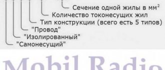
In today’s article we will review the induction type electrical energy meter – SO-505. This electricity meter has already been discontinued and has been replaced by more modern models.
SO-505 is used in single-phase circuits and records electricity at one tariff (single-tariff) on an accrual basis. Information is displayed on a mechanical readout mechanism. The number of revolutions of the induction disk is proportional to the currently consumed electricity. In this way, you can determine what current electricity consumption is; to do this, you need to take the meter constant (600 revolutions x 1 kW/hour), which shows the ratio of revolutions to electricity consumed.
Life time
The average minimum service life of SO-505 is at least 30 years. After 30 years of operation of the meter, it can continue to be used if it works correctly. Additionally, the manufacturer claims a minimum of 280,000 hours of continuous operation until failure, which is approximately 31 years of operation.
As mentioned earlier, this meter model has been discontinued; at the time of sale, the price of the electric meter varied from 700 to 800 rubles. Now a more modified model SO-52 is being produced and can be purchased.
Electric meter installation
The connection diagram for the CO-505 electric meter is quite simple, but it requires the technician to follow the advice of professionals, as well as all stages of the process. Only in this case can you achieve the desired result and complete the work in the shortest possible period of time.
Recommendations from experts
In order for a self-installed device to work effectively and perform its functions well, it is necessary to take into account the advice of highly qualified specialists. They will help beginners avoid most mistakes and do the job as efficiently as possible.
Useful tips:
- Before starting installation, you should carefully study the device of the meter, the rules of its operation, as well as safety requirements.
- The CO-505 electric meter, like any other induction-type design, does not withstand the effects of cold. Because of this, it is recommended to carry out installation at a temperature of at least 5 degrees above zero (Celsius).
- If the device is installed outdoors, it must be protected from rain, snow and other natural phenomena. To do this, it is best to build a sealed housing and equip it with heating elements.
- When choosing a location for placing the device, you should take into account not only safety requirements, but also the height characteristics of people who are constantly in the room. It is important that taking readings is convenient for each of them. It is recommended to mount the meter at a height of 1 to 1.7 meters.
- All installation tools used must have insulated handles. This will help prevent electric shock and all its negative consequences.
You may be interested in the principle of operation of electronic and mechanical time relays
Required materials and tools
In order to simplify the process of installing a single-phase meter SO-505, it is necessary to select the right tools and materials. They can be bought in specialized stores in any locality at a relatively low price. This allows even people with little financial means to do the work themselves.
During the installation process you will need the following items:
- shield;
- single-phase meter SO-505;
- wire cutters, pliers, screwdriver (with insulated handles);
- circuit breakers;
- insulators;
- wires;
- fastening elements (nuts, screws and others);
- indicator screwdriver;
- DIN rails.
Step-by-step installation
To ensure that self-installation of an electricity meter does not cause any complaints from the energy sales service, you must comply with all the rules provided by law. You should contact the appropriate organization, write an application and obtain permission to carry out work. After receiving all the necessary documents and familiarizing yourself with the requirements for installing the meter, you can begin work.
Procedure:
- The number of switches is calculated based on the parameters of the equipment and the electrical network.
- The room is disconnected from electricity.
- Using a special indicator screwdriver, the presence of voltage in the network is checked.
- The body of the protective shield opens and the purchased device is installed in it.
- There it is securely fastened using special clamps included in the CO-505 package.
- At the next stage of work, the wires running from the input machine to the electric meter are prepared.
- Three phase cables are inserted into the device and connected to the lower terminals.
- After this, the neutral wires are output.
- The DIN rail is attached to the support insulators with screws.
- Switches are attached to it using a special latch with a spring.
- A grounding and protective bus is attached to the DIN rail. This is done using ordinary screws and nuts. It is important to place the elements in such a way as to eliminate the possibility of them touching and shorting.
- The load is connected to the switches. To do this, the phase is fixed in the lower terminals of the switches, and the zero is fixed in the zero bus. The ground wires are connected to the corresponding busbar.
- The machines are connected to a metering device.
- The CO-505 connection is made by connecting the phase to the upper terminal of the machine. The zero must be secured to the zero bus.
- The shield is installed in a pre-selected location.
- The neutral wire is connected to the third terminal of the electric meter, and the phase is connected to the first.
- All wire attachment points are additionally insulated.
- The installed device is checked for functionality. If any problems are found, they are immediately eliminated.
After completing the installation, you should contact the energy sales service again and write an application for inspection and sealing of the device. At the appointed time, a representative of this organization will come and perform all the necessary actions. After this, the CO-505 electric meter can be used.
How to take readings
In order to record meter readings and make payments, we use the general rules for reading. If there is a comma on the meter display, or the right side of the numbers is separated by a frame or another color, then write down all the numbers that are to the left of the frame or comma, this is the number of whole kilowatts, on the right are tenths of kilowatts.
For a more detailed study of the technical characteristics of the CO-505 electric meter and operating rules, you can use the technical data sheet of the device and the user manual, which are attached below.
Passport of the meter SO-505
Single-phase meter connection diagram
Single-phase electronic electricity meters installed in apartments have almost identical connection diagrams. This is a direct connection circuit. This connection diagram for a single-phase meter does not depend on the type of meter being selected or already installed. A characteristic feature of a single-phase meter is the presence of four terminals on the housing for connecting an electrical cable.
A phase wire is connected to the first terminal, which is the input. The second terminal is connected to the wire that goes to the apartment for the load and is the output. The neutral wire is connected to the third terminal, this is the input. And the neutral wire going to the load (output) is connected to the fourth terminal.
As you can see, there is nothing fancy when connecting, so you can connect a single-phase meter yourself. As a rule, the connection diagram is available on the inside of the electric meter housing. The peculiarities of connecting the electric meter will consist only in the mounting method: on the housing or DIN rail.
How to install a single-phase electric meter is shown in this video.
Types of meters and their key features
| Parameter | Classification of electricity meters |
| Type of current used | constant and variable |
| Number of phases | single-phase, three-phase |
| Number of tariffs | single and multi-tariff |
| working mechanism type | mechanical, electronic and hybrid electricity meters - a rarely used intermediate option with a digital interface, an inductive or electronic type measuring part, a mechanical computing device |
| By connection type | devices for direct connection to the power circuit and devices for transformer connection, connected to the power circuit through special instrument transformers |
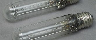
There are two main types of meters on the market: induction and electronic. They differ in their mechanism of action and measurement accuracy.
Induction models are rapidly being forced out of the market. The government is actively promoting this. The main disadvantage of devices in this category is that they are very easy to “deceive,” which unscrupulous consumers happily take advantage of.
Induction meters
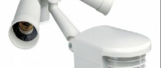
Electronic meters are more versatile, compact and accurate. An additional advantage of modern models is the ability to configure them to operate in multi-tariff mode. This point is especially relevant for consumers living in regions with different electricity tariffs during the day and at night.
Three-phase electronic electricity meter MTX3 with GSM
Thus, when choosing the type of meter for self-installation, it is strongly recommended to give preference to modern electronic models.
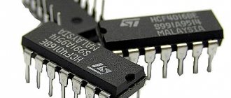
Additionally, meters are classified according to indicators such as accuracy class and rated current. The smaller the meter class number, the more accurately it works.
Counter NIK NIK 2102
The required rated current is determined individually. To calculate, check with your local energy sales office for the permissible active power indicator established per consumer. This number must be divided by 220V or 380V depending on the voltage of your electrical network.
For users connected to a three-phase network, a higher active power threshold is usually set, however, using a three-phase connection in everyday life is not entirely advisable.
In such situations, it is important to take into account that the inclusion of intermediate elements in the circuit can negatively affect the accuracy of accounting, so planning a transformer circuit must be approached with knowledge. To do this, it is better to contact a qualified specialist.
Electricity meters
When choosing a meter, be sure to pay attention to the integrity of the seal and how long ago it was installed. You will find the seal on the screws of the meter casing
The maximum permissible limitation period for installing a seal for single-phase devices is 12 months, for three-phase devices - 24 months.
Connecting a three-phase meter
Three-phase electricity meters and the method of connecting them depend on various features of the electrical installation. There are several different connection types.
- Switching on is direct.
- Creating a four-wire network using current transformers.
- Two transformers and three network wires and two voltage transformers.
- Three and four wire network and voltage and current transformers.
A three-phase meter has eight connectors for connection. In principle, connecting a three-phase meter is almost the same as a single-phase one, the only difference is the large number of phases for connection. And there is no difference in how a three-phase electric meter with an ouzo is connected.
Most often, this type of meters is connected using the direct connection method. It is produced on a four-wire network with an operating voltage of 380V.
Must remember!
For any, even independent connection of metering devices, both single-phase and three-phase, it is necessary to observe and mark the wires!
And so the alternation itself occurs clockwise, so the following is obtained: ABC-BSA-CAB. If you make the connection in the reverse order, there is a high probability that the device may begin to give false readings, which will be expressed in minor errors.
For a more accurate connection and correct installation, you must use the connection diagram. It can be designated as follows (Fig. 5):
- the existing phase designated as “A” will be yellow;
- the phase under the beech “B” is green;
- phase “C” - red;
- zero is blue;
- L (1,2,3) – current coils;
- L (4,5,6) – voltage coil;
- digital designations - two, five, eight are voltage screws;
- 1, 3, 4, 6, 7, 9, 10, 11 are terminals; they are needed to connect the electrical wiring to the meter.
In order to correctly connect the meter yourself, you need to study the connection diagram of this device very carefully and in great detail. And only when everything becomes extremely clear can you start connecting it.
Rice. 5. Connection diagram for a three-phase meter
It should be understood that connecting an electric meter, of course, is not the most difficult thing that can be
But as with any work with electricity, it is important to observe increased safety precautions.
An electricity meter is a device that records electricity consumption. Sometimes it becomes necessary to change or install a new meter. Despite the huge variety in choice, the connection diagram for the electric meter remains unchanged. You can connect the electric meter directly in a garage, country house, or apartment. Connection via a current transformer is carried out, as a rule, at manufacturing enterprises and other large consumers of electricity.
First, let's decide what type of device we need.
Electricity meters are divided into two types: induction and electronic. An induction meter is an electromechanical device. Accounting is carried out by the number of revolutions of the device disk.
An electronic meter does not have a mechanical disk. Electricity is taken into account by processing signals coming from sensors.
The accuracy class of electronic meters is higher than that of induction meters.
In addition, their price is lower than that of induction meters.
Counter selection options:
- Number of phases in the network.
The network can have one phase or three. Therefore, meters are produced either single-phase or three-phase. - Accuracy class.
This is the amount of error that the device can allow during measurements. There are several accuracy classes, ranging from 0.2 percent to 2.5 percent accuracy. They differ from each other by 0.5 percent. The accuracy class of the device installed in housing must correspond to class 2.0. - Connection method.
Electricity meters are connected to the network in two ways. The first is direct connection. Applicable if current is less than 100 amperes. The second method is used for currents above 100 amperes. In this case, the connection diagram contains a current transformer. - Mains voltage.
For now we are interested in a voltage of 220 V. - Electricity tariffs.
There are three types of meters that calculate electricity in accordance with tariffs:
- Single tariff meters. They are still used most often.
- Two-tariff meters. Such meters provide metering at day and night rates. The daily rate is valid from 7 a.m. to 11 p.m. Night from 11 pm to 7 am. The cost of the night rate is almost two times lower.
- Multi-tariff meters. Rarely used.
Advantages of the device
The advantages of the energy meter include the following features:
- expanded values for permissible stresses;
- ability to control loads using a built-in relay;
- increased protection from external influences;
- economical energy consumption;
- high accuracy of recording indicators;
- convenient and compact body designs;
- availability of connecting a third-party power supply;
- presence of screen backlight;
- alarms about magnetic and electromagnetic influences;
- functions for indicating errors in operation and connection;
- allowed setting of permissible parameters with a shutdown function in case of overload.
- meter design according to the type of energy being measured and the network connection diagram;
- execution of the counter via additional interfaces;
- active energy functioning indicator;
- indicator of reactive energy functioning;
- optical port;
- optical port sealing screw;
- fillings;
- casing sealing screws;
- optical port cover;
- terminal cover sealing screws;
- terminal cover;
- optical button “Perspective”;
- LCD
Despite the production not in Russia, the device is made in full compliance with established domestic standards and is allowed for use in the Russian Federation.
Sealing a single-phase meter
The connection of a single-phase electricity meter in the apartment, as well as subsequent monitoring, is carried out by regulatory organizations. The correctness and correctness of the connection in accordance with the established energy consumption standards is confirmed by the sealing of the device.
Sealing the device - the electric meter - eliminates the possibility of independently altering or completing the connection of the meter. Thus, the practicality and expediency of installing this type of meter is confirmed by the relevant regulatory organization of Energonadzor.
The electric meter is used to record consumed electricity. A situation often arises when it becomes necessary to replace or install a new one. Currently, there is a variety when choosing such devices, but the connection diagram of the electric meter remains unchanged.