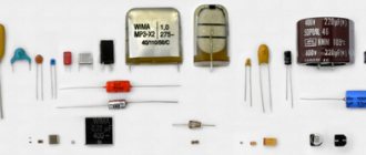
Code marking
According to IEC standards, in practice there are four ways to encode the nominal capacity.
Three digit encoding
The first two digits indicate the capacitance value in picofarads (pF), the last two digits indicate the number of zeros. When the capacitor has a capacitance of less than 10 pF, the last digit may be "9". For capacitances less than 1.0 pF, the first digit is “0”. The letter R is used as a decimal point. For example, code 010 is 1.0 pF, code 0R5 is 0.5 pF.
Table 1
* Sometimes the last zero is not indicated.
Four digit encoding
4-digit coding options are possible. But even in this case, the last digit indicates the number of zeros, and the first three indicate the capacity in picofarads (pF).
table 2
Capacitance marking in microfarads
The letter R may be used instead of the decimal point.
Mixed alphanumeric marking of capacity, tolerance, TKE, operating voltage
Unlike the first three parameters, which are marked in accordance with standards, the operating voltage of different companies has different alphanumeric markings.
Examples:
Picture 1
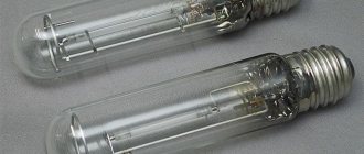
Film capacitors with polyethylene terephthalate dielectric
Electrical capacity of a flat capacitor
The listed advantages are largely explained by design features. The modifications of capacitors under consideration are created using a dielectric made from a polymer film. To reduce the inductive properties, instead of a roll, complex layer formation with pressing is used. In fact, a plurality of plate energy storage devices are created, connected in parallel.
The main advantage of this type of dielectric is its ability to self-recover. After an electrical breakdown, the created conductor gradually evaporates. The process is accelerated by the passage of current through the corresponding section of the structure, which is accompanied by heating of the corresponding area. Quite quickly without additional actions, the functional characteristics of the capacitor are normalized.
For comparison with other dielectrics, you can study the information presented below.
Capacitor parameters
| Characteristics | Dielectric type | ||
| Polyethylene terephthalate | Polypropylene | Polystyrene | |
| Loss tangent | 0,01-0,1 | 0,002 | 0,0001-0,0015 |
| Insulation resistance, MOhm | 10 000 | 50 000 | 100 000 |
| Absorption coefficient, % | 0,2-0,8 | Less than 0.5 | Less than 0.1 |
| TKE (temperature coefficient), 10-6/°C | -200 to 400 | -200 to 100 | -200 |
When choosing a polyethylene terephthalate product, you can use high structural strength and good dielectric constants. However, the relatively small loss tangent and limited insulating properties should be taken into account.
At the project preparation stage, the operating parameters of the capacitor and compliance with the conditions of future operation are comprehensively checked. To eliminate errors, it is recommended to study expert reviews of products from certain manufacturers. When choosing a supplier (store), costs and official warranty obligations are assessed.
Color coding
In practice, several color marking techniques are used to color code permanent capacitors.
* Tolerance 20%; a combination of two rings and a dot indicating a multiplier is possible.
** The color of the housing indicates the operating voltage.
The “+” terminal may have a larger diameter.
To mark film capacitors, 5 colored stripes or dots are used:
The first three encode the value of the nominal capacitance, the fourth - the tolerance, the fifth - the rated operating voltage.
Capacitor 0.1uF 100V (2A104J, CL11) | Film capacitors
Capacitors of the CL11 series (polyester capacitor) are made of metallized film dielectric. Widely used in industrial and household equipment.
Marking:
- 2A = 100V
- 104 = 100000pF (0.1uF)
- J = ±5%
Dimensions:
Datasheet: Capacitors CL11 Series.pdf
Product code: Update: Voltage: Capacity:
| M-116-11758 |
| 2019-09-20 |
| 100V |
| 4.7nF |
A huge amount of electronic components and technical information on the Dalincom website can make it difficult for you to find and select the required additional radio products, radio components, tools, etc. We have prepared the following information table for you, based on the choices of our other customers.
Related products
| Code | Name | Short description | Rozn. price |
| ** more detailed information (photo, description, labeling, parameters, technical specifications, etc.) can be found by clicking on the product description link | |||
| 11758 | Capacitor 0.1uF 100V (2A104J, CL11) | Film capacitor 0.1uF 100V (marking 2A104J) series CL11 (polyester capacitor) made of metallized film dielectric | 1.5 rub. |
| 3213 | Panel SCS-16 (DIP-16, pitch 2.54mm) | Socket for chips SCS-16 DIP panel 16-pin pitch 2.54mm | 2.5 rub. |
| 10218 | Capacitor 2200uF 50V (JCCON) | Electrolytic capacitors 2200 uF 50V (JCCON, 105°C, size 16×31 mm) | 24 rub. |
| 9728 | Variable resistor WH148-1 (B10K, 15mm) | Variable resistor WH148-1A-3, 10 kOhm, linear characteristic, L=15 mm | 12 rub. |
| 9804 | Capacitor 100uF 50V (JCCON) | Electrolytic capacitors 100 uF 50V (JCCON, LOW ESR, 105°C, size 8x12mm) | 2.4 rub. |
| 928 | Panel SCS-8 (DIP-8, pitch 2.54mm) | Socket for chips SCS-8 DIP panel 8-pin pitch 2.54mm | 1.2 rub. |
| 3551 | Capacitor 0.1uF 630V (CBB22) | Metallized film polypropylene capacitor 0.1uF 630V (CBB22 series) | 4 rub. |
| 11192 | Capacitor 4.7nF 100V (CL11) | Film capacitor 4.7nF 100V (marking 2A472J) series CL11 (polyester capacitor) made of metallized film dielectric | 0.6 rub. |
| 9104 | Trimmer resistor 3296W, 5 kOhm (5K) | Multi-turn trimmer resistor (potentiometer), type 3296W, nominal 5 kOhm | 8.5 rub. |
| 362 | Capacitor 47uF 63V (Jwco) | Electrolytic capacitors 47 uF 63V (6.3x12 mm, LOW ESR, 105°C, radial leads) | 2.4 rub. |
TKE marking
Capacitors with non-standardized TKE
* Modern color coding. Colored stripes or dots. The second color can be represented by the color of the body.
Capacitors with linear temperature dependence
* The actual spread for imported capacitors in the temperature range -55...+85'С is shown in brackets.
** Modern color coding. Colored stripes or dots. The second color can be represented by the color of the body.
Capacitors with nonlinear temperature dependence
* Designation according to EIA standard, IEC in parentheses.
**Depending on the technologies that the company has, the range may be different.
For example, the PHILIPS company for the Y5P group normalizes -55...+125 °C.
***According to EIA. Some companies, such as Panasonic, use a different encoding.
Features of coding capacitors made in the USSR
In the USSR, IEC standards were followed, so you can use the above data, but there were also minor differences.
The coded designation of nominal capacities consists of two or three numbers and a letter. The code letter is a multiplier that makes up the capacitance value (see table) and determines the position of the decimal fraction.
The permissible deviation of the capacitance value as a percentage of the nominal value is indicated by the same letters as the tolerances for the resistance of resistors, however, with some additions (see table). For capacitors with a capacitance of less than 10 pF, the permissible deviation is set in picofarads :
Capacitors are marked with a code in the following order:
- rated capacity;
- permissible deviation of capacity;
- TKE and (or) rated voltage.
Here are examples of coded marking of capacitors.
The abbreviated alphanumeric marking on the 33pKL capacitor indicates a nominal capacitance of 33 pF with a tolerance of ±10% and temperature instability of the M75 group (75x10-6 °C-1). The inscription m10SF indicates 100 µF (0.1 millifarads) with a tolerance of -20...+50% and a nominal voltage of 20 V.
A nominal capacitance of 150 pF can be designated 150p or n15; 4700pf - 4n7; 0.15 µF - µ15; 2.2μF - 2μ2.
| Capacity | ||
| Factor | Code | Meaning |
| 10-12 | p | picofarads |
| 10-9 | n | nanofarads |
| 10-6 | h | microfarads |
| 10-3 | m | millifarads |
| 1 | F | farads |
Note. The old tolerance designation is indicated in parentheses.
| Eg. IN | Lit. designation | Eg. IN | Lit. designation | Eg. IN | Lit. designation | Eg. IN | Lit. designation | Eg. IN | Lit. designation |
| 1,0 | I | 6.3 | B | 40 | S | 100 | N | 350 | T |
| 2,5 | M | 10 | D | 50 | J | 125 | P | 400 | Y |
| 3.2 | A | 16 | E | 63 | K | 160 | Q | 450 | U |
| 4.0 | C | 20 | F | 80 | L | 315 | X | 500 | V |
Breakdown of MLCC capacitors in alternating and pulsating voltage circuits
The breakdown of capacitors in alternating voltage circuits is determined by the failure of the insulation resistance. The dependence of the breakdown voltage on the capacitance value at a given frequency corresponds to the dependence in constant voltage circuits. It is especially worth considering the frequency dependence of the breakdown voltage. It has two distinct areas [6] (Figure 10):
- At low frequencies, the level of breakdown voltage is practically independent of the signal frequency. A breakdown in this region is characterized by dielectric breakdown. But the breakdown voltage is approximately 30% less than in constant voltage circuits.
- At high frequencies, voltage is associated with electrothermal breakdown.
Figure 10 – Frequency dependence of breakdown voltage
The action of alternating voltage leads to power losses and heating of the capacitor itself. The amount of overheating of the capacitor with increasing amplitude of the alternating voltage has a number of interesting features [6] (Figure 11):
- Under equal conditions, the overheating of the NPO capacitor will be less than the X7R. This is due to the fact that the tanδ value for NPO is smaller.
- The amount of overheating for NPO is approximately proportional to the square of the voltage amplitude, which corresponds to formulas (3) and (4).
- The X7R's overheating behavior is complex. As the temperature increases, tgδ changes, which leads to a change in the released power and a change in temperature.
Figure 11 – Dependence of capacitor heating on alternating voltage amplitude
Ripple voltage circuits.
It is worth noting that there are a large number of applications with a pulsating voltage form (automotive electronics, electric power supply, etc.). Each area places its own demands on the device as a whole. However, there are no specific noise immunity requirements for capacitors. Therefore, for each type of capacitor, general testing methods for a specific area are often used. That is why it is necessary to pay close attention to the test conditions and types of test influences.