The reliability of capacitors in homemade and industrial radio equipment is determined by the influence of factors that can be divided into the following groups:
- electrical loads (voltage, current, reactive power, AC frequency);
- climatic loads (ambient temperature and humidity, atmospheric pressure, biological factors, etc.);
- mechanical loads (vibration, shock, constant acceleration, acoustic noise);
- radiation effects (neutron flux, gamma rays, solar radiation).
Under the influence of these factors, the parameters of the capacitors change. Depending on the type and duration of the load, parameter deviations consist of temporary and irreversible changes. Reversible changes in parameters are caused by short-term exposure to loads that do not lead to changes in the properties of structural materials and appear only under conditions of exposure to loads. After removing the load, the parameters of the capacitors take values close to the initial ones.
Climatic loads . Ambient temperature and humidity are the most important factors affecting the reliability, durability and storage of capacitors. Prolonged exposure to elevated temperatures causes aging of the dielectric, as a result of which the parameters of the capacitors undergo irreversible changes. The maximum permissible temperature for capacitors is limited by setting the maximum positive ambient temperature and the magnitude of the electrical load.
The use of capacitors in conditions exceeding these limits is unacceptable, as it can cause a sharp deterioration in parameters (decrease in insulation resistance and electrical strength, decrease in capacitance, increase in current and loss tangent), violation of the tightness of the junctions, deterioration of the insulating and protective properties of organic coatings and potting materials, and in some cases can lead to complete loss of functionality of capacitors.
In addition to the external temperature, the capacitors can be additionally affected by the heat generated by other products that become very hot during operation of the equipment. The thermal effect on capacitors can be either continuous or periodically changing. A sharp change in temperature can cause mechanical stress in dissimilar materials, failure of solder joints, and the appearance of cracks and gaps in capacitor parts.
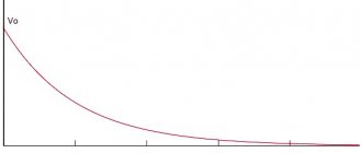
Many types of capacitors experience a decrease in capacitance at low temperatures, especially oxide and ceramic capacitors. For oxide capacitors, the loss tangent increases at low temperatures. All types of oxide capacitors with liquid or paste electrolyte at temperatures below 60 ° C are practically inoperable due to a sharp decrease in capacitance and an increase in the loss tangent. As the ambient temperature increases, the voltage across the capacitor should decrease. A typical dependence of the rated voltage on temperature is shown in the figure.
Under conditions of high humidity, the electrical characteristics of capacitors are affected by both the film of water formed on the surface and the internal absorption of moisture by the dielectric. Sealed capacitors are characterized only by adsorption processes. For capacitors that are not vacuum sealed, internal penetration of moisture is also possible.
Long-term exposure to high humidity has the greatest effect on changes in the parameters of unsealed capacitors. Unsealed paper and metal-paper, as well as compressed mica capacitors have the least moisture resistance. The penetration of moisture into capacitors reduces the insulation resistance and dielectric strength, increases the loss tangent and capacitance. Particularly dangerous for unsealed capacitors is simultaneous prolonged exposure to high humidity and electrical load. In addition to directly affecting the electrical characteristics of capacitors, moisture causes corrosion of metal parts and contact fittings of capacitors, and facilitates the development of various mold fungi. The appearance of mold can cause discoloration and destruction of protective coatings and markings, deterioration of the insulating properties of organic materials, and contributes to the formation of a layer of moisture on capacitors.
In marine areas, the harmful effects of moisture are enhanced by the presence in the atmosphere of salts that make up sea water, which increases the electrical conductivity of moistened surfaces and insulating materials, and facilitates the conditions of electrolysis and corrosion of metals.
In industrial areas, moisture condensed on the surface of capacitors may contain solutions of sulfur and other aggressive compounds that enhance the harmful effects of moisture.
When the external temperature decreases, conditions favorable for the formation of frost and dew may be created inside the equipment units. The effects of frost and dew have virtually no effect on the performance of low-voltage capacitors. However, the presence of moisture on the surface of capacitors during dew may increase surface conductivity and lead to a decrease in insulation resistance, and in high-voltage capacitors, to a decrease in dielectric strength. After the dew evaporates, the electrical characteristics of the capacitors are restored. Recovery time depends on the dimensions, design, heat capacity and other characteristics of the product. Capacitors with oxide dielectric remain fully operational when exposed to frost and dew.
During operation and transportation of equipment, capacitors are exposed to various types of mechanical loads: vibration, single and multiple shocks, linear acceleration, acoustic loads. The most dangerous are vibration and shock loads. Exposure to mechanical loads exceeding permissible limits can cause breaks in leads and internal connections, an increase in leakage current in oxide capacitors, cracks in ceramic cases and insulators, a decrease in electrical strength, and a change in the installed capacitance of tuning capacitors. High levels of destructive forces can occur when exposed to shock loads if the components of the spectrum of the shock pulse coincide with the natural resonant frequencies of the capacitor.
Radiation effects . The development of nuclear energy and space exploration puts forward the requirement for the resistance of capacitors to the effects of ionizing radiation, deep vacuum and ultra-low temperatures. Exposure to ionizing radiation can both directly cause changes in the electrical and operational characteristics of capacitors, and contribute to the accelerated aging of structural materials with subsequent exposure to other factors. The nature and rate of change in parameters depend on the dose, intensity and energy spectrum of the radiation and are largely determined by the type of working dielectric and the design of the capacitor.
The processes occurring in capacitors under conditions of exposure to ionizing radiation are fundamentally different from the aging processes under normal operating conditions. As a result of exposure to ionizing radiation, phenomena may also occur in capacitors that lead to reversible or residual changes in their electrical parameters. Reversible changes are associated with the processes of ionization of dielectric materials and air and are accompanied mainly by a sharp decrease in insulation resistance and an increase in leakage current due to the formation of surface and internal volume-distributed charges. The loss tangent also increases, especially at low frequencies. After cessation of irradiation, the insulation resistance (leakage current of oxide capacitors) is restored in most cases. Recovery time depends on the type of dielectric, dose and radiation power.
Residual changes in parameters are associated mainly with persistent violations of the structure of the working dielectric, as well as protective and filling materials. When exposed to ionizing radiation, the structure and mechanical properties of polymer materials used in film and combined capacitors change most dramatically. Structural changes are usually accompanied by intense gas release. Impregnating compositions and cellulose, which is the main component of condenser paper, undergo relatively rapid changes. Therefore, capacitors with an organic dielectric are more sensitive to the effects of radiation than capacitors with an inorganic dielectric. Type 1 ceramic capacitors are the most resistant to ionizing radiation (read about the main types in the previous article). Radiation damage to the structure of materials can also lead to a deterioration in the main operational characteristics of capacitors - service life, mechanical and electrical strength, and moisture resistance.
Electrical loads. The greatest irreversible changes in parameters are caused by prolonged exposure to electrical load, during which aging processes occur that worsen the electrical strength. This must be taken into account when choosing the operating voltage, especially during long-term operation of capacitors. At constant voltage, the main cause of aging is electrochemical processes that occur in the dielectric under the influence of a constant field and intensify with increasing temperature and humidity of the environment. The degree of their influence on the parameters of capacitors is determined by the type of dielectric and the design of the capacitor. In this case, the total change in the parameters of the capacitors does not exceed the values guaranteed for the period of minimum operating time given in the reference data.
With alternating voltage and pulse modes, the main cause of aging is ionization processes that occur inside the dielectric or at the edges of the plates, mainly in places of gas inclusions. This phenomenon is typical mainly for high-voltage capacitors. Ionization destroys organic dielectrics as a result of bombardment by the resulting ions and electrons, as well as due to the aggressive effect of the resulting ozone and nitrogen oxides on the dielectric. For ceramic materials, ionization in a closed pore causes strong local heating, which results in mechanical stresses, accompanied by cracking of the ceramic and breakdown along the crack.
Despite the fact that the permissible value of the electric field strength in the dielectric of a capacitor during testing is selected with some margin, operation under an electrical load exceeding the rated voltage sharply reduces the reliability of capacitors. Exceeding the permissible alternating voltage component can cause thermal imbalance in the capacitor, leading to thermal destruction of the dielectric. This is due to the fact that the active conductivity of the dielectric will increase with increasing temperature.
Type 1 protected ceramic capacitors are the most resistant to electrical operating loads and stable. Among oxide capacitors, sealed oxide semiconductor capacitors are the most stable. The low stability of electrolytic oxide capacitors is explained by the presence of a liquid or paste electrolyte in them, the resistance of which is more dependent on the ambient temperature than that of oxide-semiconductor capacitors. Prolonged exposure to an electrical load, especially at elevated temperatures, causes evaporation of volatile fractions of the electrolyte, which further increases the resistance of the electrolyte and sharply worsens the temperature and frequency dependence of the capacitance and loss tangent. This process occurs most intensively in small-sized aluminum capacitors with an electrolyte based on dimethylformamide.
During long-term operation under an electrical load of some types of tantalum electrolytic capacitors, the capacity may decrease due to passivation of the cathode, as well as failures associated with the destruction of the silver case and the resulting leakage of electrolyte. Increasing the amplitude of the alternating voltage component accelerates this process. New types of capacitors with tantalum housings are free of this disadvantage and have increased stability of parameters and higher durability,
FREQUENCY PROPERTIES OF CAPACITORS
When choosing capacitors for operation in alternating or pulsating current circuits, it is necessary to take into account their frequency properties, determined by a number of design factors: type of dielectric, values of inductance and equivalent series resistance, design. The performance of capacitors at alternating voltage is limited mainly by the following factors:
- heat generation proportional to the average power, which can increase sharply when permissible operating conditions are exceeded and create conditions for thermal breakdown of the capacitor;
- the intensity of the electric field acting on the dielectric of the capacitor and causing its electrical aging;
- current flowing through the capacitor, at a high density of which local overheating and destruction of contact nodes, burnout of metallized plates are possible;
- ambient temperature.
Ceramic capacitors of type 1, mica and capacitors made of non-polar films (polystyrene, polypropylene, etc.) have the highest frequency properties. Due to the fact that with increasing frequency, energy losses in the capacitor increase, to maintain thermal balance in the capacitor and eliminate the possibility of breakdown with increasing frequency it is necessary to reduce the amplitude of the variable component. For a number of groups of capacitors, the effective capacitance may noticeably decrease with increasing frequency. The decrease in capacitance with increasing frequency occurs both due to a decrease in the dielectric constant of the dielectric and due to an increase in the equivalent series resistance (ESR). The influence of ESR on the value of effective capacitance is determined by the relationship:
ESR is caused by losses in the capacitor - in the dielectric, in metal parts, in transient contact resistances, in the electrolyte of oxide capacitors. In conventional capacitors, the ESR is quite small (fractions of an ohm) and a decrease in capacitance with frequency can only be noticed in the high frequency region. The strongest dependence of capacitance on frequency occurs in oxide capacitors (especially with liquid electrolyte) due to the high resistivity of the electrolyte and its dependence on frequency. For these capacitors, a decrease in capacitance with frequency is observed starting from hundreds of hertz.
These mysterious capacitors
This article is about the features of ceramic capacitors that appear at high frequencies (of the order of tens, hundreds of megahertz and higher). The article is based on research materials conducted by specialists from Johanson Technology. We will mainly talk about ceramic capacitors suitable for use in:
- High-speed digital devices (filtering of own and external interference);
- High-frequency devices (filtering, RF matching, RF signal processing, etc.);
- Any other devices for filtering external high-frequency interference, which can come both through power circuits and through the air from wireless communication devices and systems, radio stations, power electronics devices, etc.
In the production of such capacitors, special dielectrics are used, which are called NPO
or
COG
.
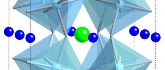
These dielectrics are known for providing a weak dependence of the capacitor's capacitance on the ambient temperature and applied voltage. Most often, to reduce their size, ceramic capacitors are made in the form of multilayer ceramic capacitors - MLCC, Multilayer Ceramic Capacitor
, the structure of which is shown in the following picture:
Johanson Technology is one of the world leaders in the production of high-frequency ceramic capacitors.
, the materials of which served as the basis for this article.
What happens to capacitors as the frequency increases?
As the operating frequency increases, the first “special” frequency that researchers encounter is the series resonant frequency – SRF, Series Resonant Frequency
. As you know from a physics course, this is the frequency at which the reactance of an ideal capacitor is compensated by the reactance of a series-connected ideal inductor in such a way that the total resistance of the circuit becomes zero. In the case of a ceramic capacitor, the phenomenon of series resonance is explained by the presence of parasitic inductance of the leads and plates of the capacitor. And the remarkable SRF in our case is as follows:
- At series resonance frequency (SRF), the capacitor has the lowest resistance, called equivalent series resistance - ESR, Equivalent Series Resistance
. This fact makes it possible to obtain a narrow-band filter instead of a capacitor, which can be used to filter out interference. - At frequencies higher than SRF, the capacitor behaves like an inductor! Therefore, it is sometimes said that at frequencies above the series resonance frequency, the capacitor is an inductance that does not allow direct current to pass through - DC blocking inductor
.
As the frequency increases further, a number of frequencies can be observed at which the multilayer capacitor has a relatively high resistance. Such frequencies are called parallel resonance frequencies - PRF, Parallel Resonant Frequency
. The presence of a series of parallel resonances is explained by the presence of parasitic capacitances connected in parallel with the “DC blocking inductor”.
It is interesting to note that in the general case, according to experimental data, a rough estimate of the frequency of the first parallel resonance can be obtained by doubling the frequency of the series resonance.
Another interesting fact is that you can get rid of all odd frequencies of parallel resonance, including the first one, simply by placing the plates of the internal plates of a multilayer capacitor not parallel to the surface of the printed circuit board, but perpendicular!
Look at the example of the dependence of the introduced attenuation on the frequency for two variants of the arrangement of the plates, which is given by Johanson:
In the top picture the capacitor plates are located parallel to the printed circuit board, and in the bottom picture they are perpendicular.
It is assumed that the disappearance of odd PRF frequencies is due to a decrease in parasitic capacitances between the ceramic capacitor plates and the printed circuit board. But why do the odd resonances disappear and the even ones remain? If you have any thoughts on this matter, welcome in the comments!
Since the SRF and PRF frequencies of ceramic capacitors can range over a very wide range, information about them becomes vital when designing electronic devices. In its documentation, Johanson Technology provides the values of these frequencies, with the PRF frequency corresponding to the frequency of the first parallel resonance (the capacitor plates are parallel to the board surface).
Here are typical resonant frequencies for Johanson Technology size 0402 capacitors:
And typical values of resonant frequencies for Johanson Technology capacitors size 0603:
As we can see, resonant frequencies move to lower frequencies as the capacitance increases and the size of the capacitors decreases. And this leads to a narrowing of the range of operating frequencies in the case where it is necessary for this capacitor to behave like... a capacitor!
Practical recommendations
- Carefully study the documentation for the capacitors you use to avoid situations where the “correct” circuit does not work correctly.
- Do not use low-frequency ceramic capacitors or capacitors with unknown characteristics (and especially electrolytic capacitors) to filter high-frequency interference.
- Determine the frequency ranges of interference and select filter capacitors based on these ranges. Take into account the inductance of the conductors, which is comparable to the parasitic inductance of high-frequency capacitors. To calculate the inductance of a conductor, you can use the formula: where L is the inductance, nH, x is the length of the conductor, cm, w is the width of the conductor, cm, h is the height of the conductor, cm.
- Follow the recommendations of electronic component manufacturers regarding the layout of high-frequency printed circuit boards.
- To expand the operating range, the ceramic capacitor can be installed on its side (eliminating the first parallel resonance).
- In high-frequency circuits, the series resonance frequencies of the capacitors used must be significantly higher than the operating frequency range.
To reinforce this idea, Johanson Technology experts give an example from their own experience, when, when the operating frequency approached the series resonance frequency, a capacitor with a capacity of 10 pF behaved like a capacitor with a capacity of 1000 pF! If the device uses a Bluetooth, Wi-Fi, GSM, GPS, etc. wireless communication module with an external antenna, then it is usually recommended to provide places in the antenna circuit for installing matching elements (placeholders). This allows, if necessary, painless adjustment of the high-frequency part of the boards. To simplify this task, Johanson Technology proposes to use special boxes of high-frequency components, which make the process of matching RF circuits less labor-intensive.
PULSE MODE
In pulsed modes, capacitors specially designed for these purposes and general applications can be used. However, in any case, when choosing capacitors, the features of their operation under pulsed loads must be taken into account. When assessing the possibility of operating capacitors in pulse mode, it is necessary to take into account that at short durations of the generated pulses, even a small self-inductance of the capacitor represents a large inductive reactance, which affects the shape of the pulse.
The shape of the pulse, as well as the efficiency of the device in which the capacitor is installed, can be influenced by energy losses in the dielectric and fittings of the capacitor. Therefore, when choosing capacitors for pulse modes, one should take into account their temperature-frequency dependencies of capacitance, loss tangent and impedance. To decide whether this pulsed mode is destructive for capacitors, it is necessary to take into account the phenomena associated with heating the capacitor due to pulsed currents, ionization aging of dielectrics, etc. These phenomena can lead to a violation of the electrical strength of the capacitor and its failure . Therefore, the permissible pulse load on the capacitor is determined based on the following parameters of the pulse mode: the values of positive and negative peaks of voltage and current, the swing of the alternating voltage on the capacitor, the duration of the rise and fall of the voltage, the period and frequency of pulses, and the presence of a constant component.
When using polar capacitors with an oxide dielectric in pulsed modes and with pulsating voltage, it is necessary to take into account that the constant component of the voltage must have a value that excludes the possibility of reverse polarity voltage appearing on the capacitor, and the sum of the constant and the amplitude of the alternating or pulsed voltage should not exceed the rated voltage.
AC circuit with capacitance
Author: Evgeny Zhivoglyadov. Date of publication: March 31, 2015. Category: Articles.
If a capacitor is connected to a DC circuit (ideal - without losses), then for a short time after switching on, a charging current will flow through the circuit. After the capacitor is charged to a voltage corresponding to the source voltage, the short-term current in the circuit will stop. Therefore, for direct current, a capacitor represents an open circuit or an infinitely large resistance.
If a capacitor is connected to an alternating current circuit, it will be charged alternately in one direction and then in the other.
In this case, alternating current will pass through the circuit. Let's consider this phenomenon in more detail.
At the moment of switching on, the voltage across the capacitor is zero. If you connect the capacitor to the alternating mains voltage, then during the first quarter of the period, when the mains voltage increases (Figure 1), the capacitor will charge.
Figure 1. Graphs and phasor diagram for an AC circuit containing a capacitance
As charges accumulate on the capacitor plates, the capacitor voltage increases. When the network voltage reaches its maximum by the end of the first quarter of the period, the capacitor charges stop and the current in the circuit becomes zero.
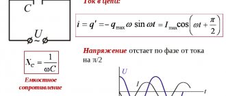
The current in the capacitor circuit can be determined by the formula:
where q is the amount of electricity flowing through the circuit.
From electrostatics it is known:
q = C × uC = C × u,
where C is the capacitance of the capacitor; u – network voltage; uC is the voltage on the capacitor plates.
Finally, for the current we have:
From the last expression it can be seen that when (positions a, b, d) is maximum, i is also maximum. When
(positions b, d in Figure 1), then i is also equal to zero.
In the second quarter of the period, the network voltage will decrease and the capacitor will begin to discharge. The current in the circuit reverses its direction. In the next half of the period, the network voltage changes its direction and the capacitor is recharged and then discharged again. From Figure 1 it is clear that the current in a circuit with a capacitance in its changes is 90° ahead in phase
voltage across the capacitor plates.
Comparing the vector diagrams of circuits with inductance and capacitance, we see that inductance and capacitance have the exact opposite effect on the phase of the current.
Since we noted above that the rate of change of current is proportional to the angular frequency ω, from the formula
we similarly obtain that the rate of change of voltage is also proportional to the angular frequency ω and for the effective value of the current we have
I = 2 × π × f × C × U.
Designating
, where xC is called
capacitance , or capacitance reactance .
So we have obtained the formula for capacitance when switching on a capacitance in an alternating current circuit. From here, based on the expression of Ohm's law, we can obtain the current for an alternating current circuit containing a capacitance: Voltage across the capacitor plates
UC = IC × xC.
That part of the network voltage that is present on the capacitor is called capacitive voltage drop , or reactive voltage component , and is designated UC.
The capacitance xC, like the inductive reactance xL, depends on the frequency of the alternating current.
But if with increasing frequency the inductive reactance increases, then the capacitive reactance, on the contrary, will decrease.
Example 1. Determine the capacitive reactance of a 5 µF capacitor at different mains voltage frequencies. We will calculate the capacitance at a frequency of 50 and 40 Hz:
at a frequency of 50 Hz:
at a frequency of 400 Hz:
Let's apply the formula for average or active power for the circuit in question:
P = U × I × cos φ.
Since in a circuit with a capacitance the current leads the voltage by 90°, then
φ = 90°; cos φ = 0 .
Therefore, the active power is also zero, that is, in such a circuit, as in a circuit with inductance, there is no power consumption.
Figure 2 shows the instantaneous power curve in a circuit with a capacitance. It can be seen from the drawing that in the first quarter of the period, a circuit with a capacitor takes energy from the network, which is stored in the electric field of the capacitor.
Figure 2. Instantaneous power curve in a circuit with capacitance
The energy stored by the capacitor by the time the voltage across it passes through the maximum can be determined by the formula:
In the next quarter of the period, the capacitor is discharged to the network, giving it the energy previously stored in it.
During the second half of the period, the phenomenon of energy fluctuations repeats. Thus, in a circuit with a capacitor, only energy is exchanged between the network and the capacitor without losses.
Source: Kuznetsov M.I., “Fundamentals of Electrical Engineering” - 9th edition, revised - Moscow: Higher School, 1964 - 560 p.
TIPS FOR SELECTING AND USING CAPACITORS
The operational reliability of capacitors is largely determined by the correct choice of capacitor types when designing equipment and using them in modes not exceeding permissible ones. To select the correct capacitors, it is necessary to determine, based on an analysis of the equipment requirements:
- values of nominal parameters and their permissible changes during operation (capacitance, voltage, insulation resistance, etc.);
- permissible modes and operating electrical loads (operating frequency range, amplitude and frequency of the alternating voltage component, reactive power, pulse mode parameters);
- operational factors (range of operating temperatures, magnitude of mechanical loads and relative ambient humidity);
- indicators of reliability, durability and storage of capacitors;
- capacitor design, installation methods, dimensions and weight.
In order to increase the reliability and durability of capacitors, in all possible cases they should be used under less severe loads and in lighter modes than permissible.
Installation and fastening of capacitors . The methods used for mounting and fastening capacitors must provide the necessary mechanical strength, reliable electrical contact and the exclusion of resonance phenomena during exposure to vibration loads. Depending on the design, capacitors are fastened to the chassis, panels and equipment boards using fastening devices (flanges, threaded connections), using brackets, clamps, rivets, or by gluing, filling and soldering to the terminals. Fastening devices must not damage the housing and protective coatings of the capacitors. Mounting devices must not impair the conditions for heat removal from the capacitors. It is not allowed to use the spade terminals of capacitors to solder other parts to them.
Mountings for vacuum capacitors, which are also contact devices, must be made of materials with high thermal conductivity and ensure good thermal and electrical contact with the terminals of the capacitors. The surfaces of the fastenings mating with the terminals of the capacitors must be silver plated. When installing in equipment, capacitors should be secured without distortions, since the presence of the latter creates mechanical stress in the cylinder and can lead to loss of tightness and failure of the capacitor. The terminals of the outer electrodes of the capacitors should be connected to a low-potential point of the device or grounded. For variable capacitors, it is recommended to ground the terminal of the moving electrode. When pairing the adjusting screw of a variable capacitor with the output of the drive, attention should be paid to ensuring the alignment of these elements or to provide for their flexible connection.
Contacting the capacitor terminals with other elements is usually done by soldering or welding. Soldering should be done with acid-free fluxes; in this case, dangerous overheating of the capacitor output nodes should not occur. It is allowed to solder the leads at distances from the housing smaller than those specified in the standard documentation, while protecting the contact unit from overheating and damage using thermal shields and heat sinks, as well as one-time bending of the wire and petal leads of the capacitors, provided that the contact unit is protected from damage at the time of bending. The bending radius of the leads must be at least one and a half diameter of the wire lead or one and a half thickness of the tape lead. When installing non-polar capacitors with an oxide dielectric, it is necessary to ensure that their cases are insulated from other elements, the chassis and from each other.
Electronov.net | Library
Dielectric loss tangent:
Since real media are anisotropic and inhomogeneous, the dielectric constant will have a complex form:
The dielectric loss tangent is expressed by the ratio of the imaginary and real parts of the complex dielectric constant:
Where:
γ – conductivity of the medium;
ω – oscillation frequency;
εа – absolute dielectric constant.
It is obvious that an ideal dielectric has a conductivity γ→ 0 , therefore, the loss tangent shows the degree of difference between a real dielectric and an ideal one.
Electrical insulation resistance of the dielectric of the capacitor Rd, leakage current and self-discharge:
Insulation resistance is the resistance of the capacitor to direct current, given by where: U is the voltage applied to the capacitor, Ileak. — leakage current.
Due to the leakage current flowing through the dielectric layer between the plates and along the surface of the dielectric, a pre-charged capacitor loses charge over time (capacitor self-discharge). Often, in capacitor specifications, leakage resistance is determined through the time constant τ of self-discharge of the capacitor, which is numerically equal to the product of the capacitance and the leakage resistance:
τ is the time during which the initial voltage on a capacitor not connected to an external circuit will decrease by e times.
Good capacitors with polymer and ceramic dielectrics have self-discharge time constants reaching many hundreds of thousands of hours.
Dielectric absorption:
If a charged capacitor is quickly discharged to zero voltage by connecting a low-resistance load, and then remove the load and observe the voltage at the terminals of the capacitor, you can see that the voltage on the plates will reappear, as if the capacitor was not discharged to zero. This phenomenon is called dielectric absorption (dielectric absorption). The capacitor behaves as if many series RC circuits with different time constants are connected in parallel to it. The intensity of this effect depends mainly on the properties of the dielectric of the capacitor.
A similar effect can be observed on almost all types of dielectrics. In electrolytic capacitors it is especially bright and is a consequence of chemical reactions between the electrolyte and the plates. For capacitors with a solid dielectric (for example, ceramic and mica), the effect is associated with residual polarization of the dielectric. Capacitors with non-polar dielectrics have the lowest dielectric absorption: Teflon (fluoroplastic), polystyrene, polypropylene, etc.
The effect depends on the charging time of the capacitor, the short-circuit time, and sometimes on the temperature. The quantitative value of absorption is usually characterized by the absorption coefficient, which is determined under standard conditions.
Parasitic piezoelectric effect:
Many ceramic materials used as dielectrics in capacitors (for example, barium titanate, which has a very high dielectric constant in not too strong electric fields) exhibit the piezoelectric effect - the ability to generate voltage on the plates during mechanical deformation. This is typical for capacitors with piezoelectric dielectrics. The piezoelectric effect leads to electrical noise in devices that use such capacitors when the capacitor is exposed to acoustic noise or vibration. This undesirable phenomenon is sometimes called the "microphone effect".
Also, such dielectrics exhibit the inverse piezoelectric effect - when operating in an alternating voltage circuit, alternating deformation of the dielectric occurs, generating acoustic vibrations that generate additional electrical losses in the capacitor.
Self-healing:
Capacitors with a metallized electrode (paper and film dielectric) have the important property of self-healing (cleaning) electrical strength after dielectric breakdown. The self-healing mechanism consists in burning off the metallization of the electrode after a local breakdown of the dielectric through a microarc electric discharge.
To main§ 55. Capacitance in the alternating current circuit
In Chapter I, § 10, the process of charging and discharging a capacitor connected to a direct current circuit was explained. Let us now consider an alternating current circuit (Fig. 58, a), which includes an electric capacitance (capacitor). We neglect the active resistance of this circuit ( r
= 0).
The polarity of the terminals of an alternating current generator connected to a circuit with a capacitor changes with a frequency ω = 2π f
.
In the first quarter of the period (Fig. 58, c), the capacitor is charged and electric charges of opposite sign appear on its plates (plus on the left plate, minus on the right). When the capacitor is charged, electric charges move along the wires connecting the generator to the plates, therefore, a charging current flows, measured by a milliammeter. No current passes through the dielectric of the capacitor. As can be seen in the wave diagram, in the first quarter of the period while charging the capacitor, the voltage on the capacitor plates increases from zero to the maximum value, the current strength, on the contrary, at the beginning of the charge will be maximum, and at the end of the charge, when the voltage on the capacitor ( Uc
) will be equal generator voltage (
Ug
), it will become equal to zero.
During the second quarter of the period, the generator voltage gradually decreases and becomes equal to zero. At this time, the capacitor is discharged. In this case, the discharge current flowing through the wires has a direction opposite to the direction of the charge current. During the third quarter of the period, the polarity at the generator terminals will change and the voltage will increase from zero to the highest value. At this time, the capacitor will charge again, but the polarity on its plates will change. The left plate will have a negative charge and the right plate will have a positive charge. A charging current will pass through the wires, the strength of which by the end of the capacitor charge, when Uc
=
Ug
, will become zero.
In the fourth part of the period, the generator voltage decreases and becomes equal to zero. At this time, the capacitor is discharged a second time, and a discharge current flows again through the wires connecting the generator to the capacitor plates. From the above it follows that during one period of alternating voltage change the process of charging and discharging the capacitor occurs twice and at the same time alternating current flows in its circuit. In addition, when charging and discharging a capacitor, the current in the circuit and the voltage are out of phase. The current is ahead of the voltage in phase by a quarter of the period, i.e. by 90°. Let's construct a vector diagram for an alternating current circuit with a capacitance (Fig. 58, b). To do this, we plot the current vector I
on the selected scale horizontally.
To show on a vector diagram that the voltage lags behind the current by an angle φ = 90°, we plot the voltage vector Uc
down at an angle of 90°.
Let's find out what the current strength in a circuit with a capacitance depends on. Let us denote the circuit resistance Xc
and call it capacitive reactance. Then Ohm's law for a circuit with a capacitance can be expressed as follows:
where U
— generator voltage,
V
;
Xc
- capacitance,
ohm
;
I
is the current strength,
and
. It is known that the current strength in a circuit is determined by the number of electrical charges passing through the cross-section of the conductor per unit time:
If a large number of charges flow through the wires per unit of time, then the current strength will be large, and vice versa, when a small number of charges flow through the wires each second, then the current strength will be insignificant. Let us assume that the frequency of the alternating current generated by the generator is high. In this case, every second the capacitor is charged and discharged many times (frequently). In the wires running from the generator to the capacitor plates, a large amount of electrical charges will move every second. Therefore, we can say that a large current appears in the circuit under consideration and in this case, according to Ohm’s law, the capacitance of the circuit is Xc
turns out to be small. If the alternating current frequency of the generator is low, the capacitor will charge and discharge fewer times every second. In this regard, a small amount of charges will pass through the wires of the circuit every second and the current strength will be small, and therefore, the capacitance of the circuit, on the contrary, will be large. From the above we can conclude that capacitance is inversely proportional to the frequency of alternating current. Capacitance depends not only on the frequency of the alternating current, but also on the amount of capacitance included in the circuit. Let us assume that a large capacitor is connected to the circuit. The amount of electricity that a capacitor accumulates when charging and releases when discharging is directly proportional to its capacity:
q = CU
.
The larger the capacitance of the capacitor included in the alternating current circuit, the greater the amount of electricity will move during charge and discharge along the wires running from the generator to its plates. Therefore, a large current arises in the wires and in this case, according to Ohm’s law, the capacitance of the circuit is Xc
there won't be enough. If the capacitance included in the circuit is small, then during charging and discharging a smaller amount of electrical charges will pass through the wires and the current strength will be insignificant, therefore, the capacitance of the circuit, on the contrary, will be large. From the above we can conclude that capacitance is inversely proportional to capacitance. Thus, the capacitance is:
where Xc
— capacitance,
ohm
;
ω - angular frequency of alternating current, rad/sec
;
C
- capacity,
f
.
It is known that the angular frequency is ω = 2π f
. Therefore, capacitance can be defined as follows:
where f
— alternating current frequency,
Hz
. If the switched capacitance is measured in microfarads, then the capacitance
If capacitance is measured in picofarads, then
It should be emphasized that there is a significant difference between capacitive and active resistance. As you know, a resistive load irreversibly consumes the energy of the alternator. If a capacitance is connected to the alternating current source, then, as discussed above, the energy of the generator is spent when charging the capacitor to create an electric field between the plates and is returned back to the generator when the capacitor is discharged. Consequently, the capacitive load does not consume the energy of the generator, and in the circuit with the capacitance, energy is “pumped” from the generator to the capacitor and back. For this reason, capacitive reactance, like inductive reactance, is called reactive.
Example.
A capacitor with a capacity
C
= 2
μF
is connected to an alternating current circuit whose frequency is 50
Hz
.
Determine: 1) its capacitance at frequency f
= 50
Hz
;
2) the capacitance of this capacitor to alternating current, the frequency of which is 500 Hz
.
Solution. Capacitance of a capacitor to alternating current at frequency f
= 50
Hz
At frequency f
= 500
Hz
From the above example it can be seen that the capacitance of the capacitor decreases with increasing frequency, and as the frequency of alternating current decreases, the capacitance increases.
For direct current, when the voltage at the circuit terminals does not change, the capacitor practically has an infinitely large resistance and therefore does not pass direct current. Previous page
| table of contents | Next page |