LM317 is an adjustable voltage stabilizer. It can be used to create various power supplies. It can be the basis for a current stabilizer, charger, laboratory power supply and even an audio amplifier. In order to use it, it is enough to connect it to one of the wiring diagrams indicated below.
This microcircuit is one of the most popular in the world - all because of the simplicity of its design and operation, its low cost and reliability. The latter is ensured by the presence of protection for short circuit of the terminals and overheating of the microcircuit. LM317 does not require many components as a harness. The microcircuit gained the greatest popularity among radio amateurs.
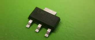
LM317 regulates voltage linearly, which is its advantage over switching converters. The microcircuit is sold in several housing options, the most popular is the LM317T version in the TO-220 housing. It was developed by Bob Dobkin in 1976 while he was working at National Semiconductor, and has been a hit in ham radio circles ever since.
LM317 circuit
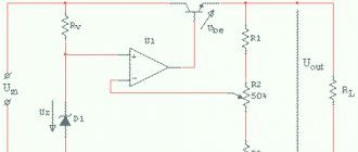
The entire internal structure of the stabilizer can be seen on its diagram, taken in the datasheet. It shows three pins of the circuit: input (power is supplied to this input), regulation and output. At the adjustment pin, the signal voltage is first reduced by a one-way limiter to a stable 1.25V and serves as a reference source, and the current, along with the supply current, goes to a comparator based on an operational amplifier.
Also in the diagram you can see an output stage based on a bipolar transistor, which amplifies the current, and a protection unit against overheating and overcurrent.
To the right of the protection unit there is a current sensor, a drop in which is monitored by the protection in order to prevent damage from short circuits.
Result:
The stabilizer is fully operational and can be used as a voltage stabilizer (subject to the presence of a load) and a current stabilizer.
There are also many different application schemes for increasing the output power, using it as a charger for batteries, etc. The cost of the subject is quite reasonable, considering that offline I can buy one for at least 30 rubles, and in a well-known Russian online store for 19 rubles, which is significantly more expensive than the one being reviewed. With that, let me take my leave, good luck!
The product was provided for writing a review by the store. The review was published in accordance with clause 18 of the Site Rules.
Characteristics of LM317
- Maximum input voltage LM317 – 40V
- LM317 output voltage range – 1.2-37V
- Maximum output current for LM317 – 1.5A
- The reference voltage of the microcircuit is 0.1-1.3V
- Minimum load current – 3.5mA
- Output voltage error – 0.1%
- Power dissipation – 20W
- Operating temperature range – 0-125C
- Storage temperature range – -65-150C
- Storage temperature range – -65-150°C
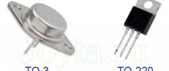
Types of LM317
The microcircuit is sold in several housing options, depending on the need for size, load and connection, as well as the type of circuit installation - everyone can choose the option that suits them best.
The most popular is the LM317T in a TO-220 1.5 Ampere package. This is considered a universal option, as it can be used in surface-mounted as well as surface-mounted applications. A radiator in such a case allows you to remove excess heat and experience more severe loads than its counterparts, and if necessary, it can be attached to a larger radiator.
Connection features
On the lm317t, the switching circuit is quite simple and consists of a minimum number of components. However, their number depends on the purpose of the device. If a voltage stabilizer is being manufactured, it will require the following parts:
Rs is a shunt resistance, which also acts as a ballast. Select a value of about 0.2 Ohm if you want to provide a maximum output current of up to 1.5 A.
The resistive divides with R1, R2, connected to the output and the housing, and the regulating voltage comes from the middle point, forming deep feedback. Due to this, a minimum ripple coefficient and high stability of the output voltage are achieved. Their resistance is selected based on the ratio 1:10: R1=240 Ohm, R2=2.4 kOhm. This is a typical voltage regulator circuit with an output voltage of 12 V.
If you want to design a current stabilizer, you will need even fewer components:
R1, which is a shunt. They set the output current, which should not exceed 1.5 A.
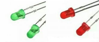
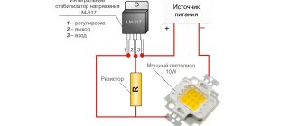
To correctly calculate the circuit of a particular device, you can always use the lm317 calculator. As for the calculation of Rs, it can be determined using the usual formula: Iout. = Uop/R1. On lm317, the LED current stabilizer is of quite high quality, which can be made of several types depending on the power of the LED:
- to connect a single-watt LED with a current consumption of 350mA, you must use Rs = 3.6 Ohm. Its power is selected to be at least 0.5 W;
- To power three-watt LEDs, you will need a resistor with a resistance of 1.2 Ohm, the current will be 1 A, and the dissipation power will be at least 1.2 W.
With lm317, the LED current stabilizer is quite reliable, but it is important to correctly calculate the shunt resistance and select its power. A calculator will help in this matter
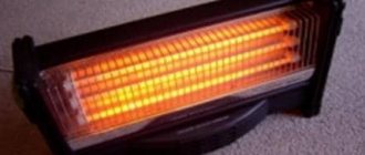
Also, various powerful lamps and homemade spotlights are made using LEDs and based on this MS.
LM317 connection
LM317 has the following pin configuration in different packages:
The minimum connection diagram consists of two resistance resistors and three capacitors connected according to the diagram. In accordance with the resistance characteristics, the output voltage will be determined.
The LM317 has two main parameters: its reference voltage, as well as the current flowing out at the trim pin. Reference voltage (Vref) is the voltage that the stabilizer maintains across resistance R1. It is unstable and varies from batch to batch by an average of 0.1V, so for calculations it is better to keep in mind the average value of 1.25V. For serious projects, it is worth measuring it for each instance used. Accordingly, following the diagram, if we close resistor R2, then at the output we will get a reference voltage of 1.25V, and with an increase in the voltage at R2, the output voltage will also increase. Thus, LM317 constantly compares the output voltage through a resistive divider with the reference, therefore, by changing the resistance, we change the output voltage.
The current flowing out at the adjustment (Iadj) is parasitic. According to manufacturers, it ranges from 50 to 100 μA, but in reality it can reach 500 μA. Because of this, for stability of the output voltage, the resistance of R1 should not be higher than 240 Ohms, so that a current of less than 5 mA does not pass through the divider.
All you need is to substitute your R1 value into this formula R2=R1*((Uo/Uref)-1).
Also, don't forget about cooling. The greater the difference between the input and output current, the more the stabilizer will heat up, which will lead to problems with its operation. The parameters described by the manufacturer can only be achieved using additional cooling in the form of a radiator.
Characteristics
Technical parameters of LM317 at ambient temperature +25 °C:
physical:
- housing TO-220, TO-220FP, TO-3, D2PAK, SOT-23;
- case material - plastic;
electric:
- range from 1.25 to 37 V;
- output current is no more than 1.5 A;
- output instability up to 0.1%;
- reference (Vref) from 0.1 to 1.3 V;
- current flowing from the adjustment pin (Iadj) from 50 to 100 µA (µA);
internal protection:
- against short circuit (Internal Short-Circuit Current Limiting);
- from thermal overload (Thermal Overload Protection);
- limitation on maximum power dissipation (Output Safe-Area Compensation);
The presence of the Output Safe-Area Compensatio parameter means that the chip has “thermal limitation” sensors that limit the maximum power dissipation; if it is exceeded, it will turn off and will not be affected.
All overload protection systems remain fully operational even if the control input is disabled.
Connection diagram
Knowing the contact numbers and their purpose, you can reduce the voltage supplied to the input of the microcircuit to the required value. To do this, you need to change the resistance of R1 connected to the adjustable terminal Adj. Let's see what it looks like.
As you can see in the lm317 connection diagram, two resistors R1 and R2 must be connected to the Adj contact. They determine the voltage that the stabilizer lowers and outputs. Let's look at the following output voltage formula.
Based on the formula, it can be seen that the value of Vout depends on the value of resistor R2. The more the value of resistance R2 increases, the greater the output voltage will be.
Typical LM317 circuits
As stated, the LM317 is used to create regulated and unregulated power supplies, however, it can also be used as the basis of a current regulator when creating LED drivers that maintain current in the circuit regardless of the input voltage. The applications described in the datasheet alone are enough to fill a separate book, so we will analyze several of the most popular circuits based on this stabilizer.
Adjustable power supply (1.2-37V)
All that is needed to create it is to replace R2 with a variable resistor, and also add a transformer with a diode bridge to the input. When using it, it is worth considering that the microcircuit has a reference voltage of 1.25V, so it will be minimal for this circuit.
Adjustable power supply (0-37V)
If you need full regulation from 0V, then circuit manufacturers suggest connecting a 10V negative voltage source to the circuit.
You can wind an additional coil on the power supply transformer and connect its leads after the diode bridge as follows:
Or you can use a negative voltage source that will be powered from the main winding.
Thus, you will get a simple laboratory power supply.
LED Driver (Current Stabilizer)
With this circuit you can power fairly powerful LEDs and LED strips. All you need is to know the current consumed and, based on it, select the resistance using the formula.
It uses the same principle as the simplest circuit, but instead of a resistive divider, a current sensor is installed. The more current the load consumes at the output, the greater the voltage drop will be observed across the sensor. It is monitored by the IC and it increases or decreases the voltage to maintain a stable current. Even in the event of a short circuit, the current will remain at the stable level that was set.
Charger
The circuit of this charger is taken from the datasheet and has an output voltage of 6V with a limit of 0.6A. By changing the resistance of resistors R1 and R2, it is possible to adjust the voltage to suit your needs, and with the help of resistor R3 - the current. It is suitable for powering batteries of phones, tools and household appliances.
AC voltage regulation
Since two LM317 can regulate not only positive, but also negative sine wave oscillations, they can be used to create an AC regulator. You can see that the circuit is quite simple and does not require many components:
Stabilized regulated power supply with overload protection
Many amateur radio power supplies (PS) are made on KR142EN12, KR142EN22A, KR142EN24, etc. microcircuits. The lower limit of adjustment of these microcircuits is 1.2...1.3 V, but sometimes a voltage of 0.5...1 V is necessary. The author offers several technical power supply solutions based on these microcircuits.
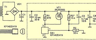
The integrated circuit (IC) KR142EN12A (Fig. 1) is an adjustable voltage stabilizer of the compensation type in the KT-28-2 package, which allows you to power devices with a current of up to 1.5 A in the voltage range 1.2...37 V. This integrated stabilizer has thermally stable current protection and output short circuit protection.
Fig.1. IC KR142EN12A
Based on the KR142EN12A IC, you can build an adjustable power supply, the circuit of which (without a transformer and diode bridge) is shown in Fig. 2. The rectified input voltage is supplied from the diode bridge to capacitor C1. Transistor VT2 and chip DA1 should be located on the radiator. Heat sink flange DA1 is electrically connected to pin 2, so if DA1 and transistor VD2 are located on the same radiator, then they need to be isolated from each other. In the author's version, DA1 is installed on a separate small radiator, which is not galvanically connected to the radiator and transistor VT2.
How to test LM317?
Unlike transistors, this microcircuit cannot be checked with a multimeter. This method does not in any way guarantee correct operation due to the large number of internal elements not connected to the terminals. Therefore, if one of them fails, then checking it with a multimeter will be problematic. The easiest way to test the operation of the LM317 is to create a simple stand on a breadboard, and it can be powered only by a battery.
This way, you can quickly verify that an item is in full working order, even if you need to check several pieces.
Application of LM317
The diagrams given above are only a small part, the basis, compared to what can be done with this stabilizer. It can be used in almost all circuits that require a constant power supply of up to 40 V. Here are some applications described in the official technical document of this chip:
- Personal computers
- Digital cameras
- ECG
- Internet switches
- Biometric sensors
- Electric motor drivers
- Portable chargers
- PoE
- RFID readers
- Appliances
- X-ray machines
As you can see, even the manufacturer himself expects the widest possible use of this element, to say nothing of home-made manufacturers who are ready to present the most unusual circuits using LM317.
Increasing the maximum output current
There are two ways to increase the maximum output current. If you need to get more than 1.5A, then you can either connect several chips in parallel, or connect a power transistor.
In the first case, it is enough to connect resistors with low resistance to the output of the stabilizers. They are needed to equalize currents.
However, it is not always rational to use several chips. Therefore, a transistor comes to our aid. In this case, it will be enough to add it and a resistor as a harness to it.
If the load draws a small current, it will pass through the chip without affecting the transistor. And when it increases, almost all the current will pass through the transistor, leaving a small part of it for the stabilizer. But when using this circuit, there is internal protection inside the LM317 from short circuit.
Schemes and calculations
The greatest use of ICs is found in power supplies for LEDs. Let's consider the simplest current stabilizer (driver) circuit, consisting of only two components: a microcircuit and a resistor.
The voltage of the power source is supplied to the input of the MI, the control contact is connected to the output contact through a resistor (R), and the output contact of the microcircuit is connected to the anode of the LED.
If we consider the most popular IM, Lm317t, then the resistor resistance is calculated using the formula: R=1.25/I (1), where I is the output current of the stabilizer, the value of which is regulated by the passport data on LM317 and should be in the range of 0.01-1 .5 A. It follows that the resistor resistance can be in the range of 0.8-120 Ohms. The power dissipated by the resistor is calculated by the formula: PR=I 2 ×R (2). Switching on and calculating IM lm350, lm338 are completely similar.
Fixed resistors are manufactured with a small variation in resistance value, so it is not always possible to obtain the desired output current value. For this purpose, an additional trimming resistor of appropriate power is installed in the circuit.
This slightly increases the cost of assembling the stabilizer, but ensures that the necessary current is obtained to power the LED. When the output current stabilizes at more than 20% of the maximum value, a lot of heat is generated on the microcircuit, so it must be equipped with a heatsink.
Read also: How to use a screwdriver with a battery indicator
Analogs LM317
What to do if it is not possible to use LM317? You can use its analogues. The twin brothers of this component are UPC317, GL317, ECG1900 and SG317. The domestic analogue is KP142EH12A, and there is also a KP142EN12 with a fixed voltage.
If the LM317 is not enough power for your project, then you can use more powerful options:
- LM350AT and LM350T – maximum output current 3A and power 25W
- LM350K – current 3 A and power 30 W
- LM338T and LM338K – current 5 A
All these microcircuits have the same pins, so the circuits do not have to be changed in any way.
What analogues exist
There are similar microcircuits developed by other companies in other countries. Complete analogues are:
- GL317;
- SG317;
- UPC317;
- ECG1900.
Stabilizers with improved electrical characteristics are also produced. More current can be produced by:
- LM338 – 5 A;
- LM138 – 5 A
- LM350 – 3 A.
If an adjustable voltage source with an upper limit of 60 V is required, stabilizers LM317HV, LM117HV must be used. The HV index means High Voltage - high voltage.
Of the domestic microcircuits, a complete analogue is KR142EN12, but it is produced only in the TO-220 package. This must be taken into account when developing printed circuit boards.
Safe operation of LM317
It is worth remembering the operational characteristics of the radio component and not using it in critical conditions. The power dissipation according to official information is 20 W, and the difference between the input and output voltages should not exceed 40 V. During soldering, the temperature should not exceed 260 C. It can be used at temperatures from 0C to 125C, and stored from -65C to 150C. All these are officially declared characteristics; in reality, they may differ from instance to instance and be underestimated.
You should not use the element at the maximum and minimum indicated values. With such operation, the level of stability and reliability will drop significantly. It is also highly advisable to use a radiator to remove heat, since otherwise the stated characteristics may not coincide with the real ones.