Preface
The goals, basic principles and procedure for carrying out work on interstate standardization are established by GOST 1.0-92 “Interstate standardization system. Basic provisions" and GOST 1.2-2009 "Interstate standardization system. Interstate standards, rules and recommendations for interstate standardization. Rules for development, adoption, application, updating and cancellation"
Standard information
- PREPARED by the Open Joint-Stock Company “All-Russian Scientific Research Institute of Certification” (JSC “VNIIS”);
- INTRODUCED by the Federal Agency for Technical Regulation and Metrology;
- ADOPTED by the Interstate Council for Standardization, Metrology and Certification (protocol dated September 30, 2014 N 70-P).
The following voted for the adoption of the standard:Short name of the country according to MK (ISO 3166) 004-97 Country code according to MK (ISO 3166) 004-97 Abbreviated name of the national standardization body Armenia A.M. Ministry of Economy of the Republic of Armenia Belarus BY State Standard of the Republic of Belarus Kazakhstan KZ Gosstandart of the Republic of Kazakhstan Kyrgyzstan KG Kyrgyzstandard Moldova M.D. Moldova-Standard Russia RU Rosstandart Ukraine U.A. Gospotrebstandart of Ukraine - By order of the Federal Agency for Technical Regulation and Metrology dated November 25, 2014 N 1745-st, the interstate standard GOST 29322-2014 was put into effect as a national standard of the Russian Federation on October 1, 2015;
- This standard is modified from the international standard IEC 60038:2009 IEC standard voltages.
At the same time, additional and amended provisions that take into account the needs of the national economy of the above states are highlighted in the text in italics, as well as a vertical line located in the margins of this text. The international standard was developed by the International Electrotechnical Commission (IEC). - INSTEAD GOST 29322-92
Information on changes to this standard is published in the annual information index “National Standards”, and the text of changes and amendments is published in the monthly information index “National Standards”. In case of revision (replacement) or cancellation of this standard, the corresponding notice will be published in the monthly information index “National Standards”. Relevant information, notifications and texts are also posted in the public information system - on the official website of the Federal Agency for Technical Regulation and Metrology on the Internet.
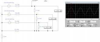
How to measure
You can measure such a system with a multimeter or using physical formulas.
Measuring Network Connectivity
LN is calculated using the Kirchhoff formula: ∑ Ik = 0. Here the current strength is zero in all parts of the electrical circuit, that is, k = 1. Ohm's law is also used: I=U/R. By applying both formulas, you can calculate the parameters of the brand or electrical network.
In a system of several lines, you will need to find the voltage between 0 and phase IL = IF. The IL and IF values are not constant and change with different connection variations. Therefore, the linear parameters are exactly the same as the phase ones.
Phase
In order to obtain phase connection readings, you will need special equipment, for example, a multimeter, voltmeter. In order to measure currents and voltages in three-phase circuits, it is usually enough to know the data of one linear current and one linear current.
Phase imbalance
FN is measured when the linear sag (falls). The square root of three is taken from linear quantities. The resulting indicator is the parameters of the physical function.
Introduction
This standard specifies voltage ratings for a.c. and d.c. electrical systems, networks, circuits and equipment used in member countries of the International Electrotechnical Commission.
This standard fully complies with the IEC 60038:2009 standard in its construction, sequence of requirements, numbering of sections and subsections. Compared to IEC 60038:2009, this standard has been updated with updated references to international standards and definitions of terms.
The lowest usable voltage in Table A.1 of Annex A of this standard is specified for a maximum voltage drop between the user's electrical installation input and the electrical equipment, which is 4%. This maximum voltage drop in the electrical circuits of an electrical installation was specified in the previous standard IEC 60364-5-52:2001. In Table G.52.1 of the currently valid standard for electrical installations connected to public electrical networks IEC 60364-5-52:2009, different values for the maximum voltage drop are established:
- for electric lamps - 3%;
- for other electrical receivers - 5%.
conclusions
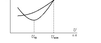
The cable voltage should first of all be selected based on the maximum voltage in the system. The maximum voltage for which the cable is rated must be greater than or equal to the maximum system voltage
Um.cable ≥ Um.network
Next, you need to understand the operating mode of the network. If the network operates with an isolated neutral (like most 6-35 kV networks), then it is necessary to determine the length of time during which the system can operate in single-phase earth fault mode.
Next, according to Table 1, U0 of the cable is selected, corresponding to the network operating mode. If the network in terms of operating mode belongs to category C, then a cable with a higher U0 value is required. This is explained by the fact that in the mode of a single-phase ground fault in a network with an isolated neutral, the voltage between the grounded parts of the equipment (screen) and the undamaged phases becomes equal to the line voltage of the network
U0.network.emergency.r = Ul.network
If for a network of category C you use a cable with a U0 value similar to that for networks of categories A and B, an instantaneous breakdown of the cable insulation during a single-phase ground fault will not occur (in the absence of dangerous overvoltages). However, the service life of such a cable is reduced.
As for cables with a rated voltage of 35 kV, unfortunately, they are not described in the IEC 60183 and IEC 60502-2 standards. But the approach to their selection should remain the same.
Literature
- IEC 60183 Selection Guide for High Voltage AC Cables
- IEC 60502-2. Revision 2.0 2005-03. Power cables with extruded insulation and fittings for rated voltages from 1 kV (Um = 1.2 kV) to 30 kV (Um = 36 kV) Part 2: Cables for rated voltages from 6 kV (Um = 7.2 kV) to 30 kV (Um = 36 kV)
Alexey Bobkov
Author of the article, design engineer of relay protection systems for stations and substations
Application area
This standard applies to :
- on alternating current electrical systems with a rated voltage of more than 100 V and a standard frequency of 50 Hz or 60 Hz, used for the transmission, distribution and consumption of electricity, and electrical equipment used in such systems;
- for AC and DC traction systems;
- for alternating current electrical equipment with a rated voltage of less than 120 V and a frequency (usually, but not exclusively) 50 or 60 Hz, direct current electrical equipment with a rated voltage of less than 750 V. Such equipment includes batteries (from cells or accumulators), other power sources AC or DC, electrical equipment (including industrial and communications) and household electrical appliances.
This standard does not apply to voltages used for receiving and transmitting signals or for measurements. The standard does not apply to standard voltages of components or parts used in electrical devices or electrical equipment.
This standard specifies standard voltage values that are intended to be used as:
- preferred values for the nominal voltage of electrical power systems;
- reference values for electrical equipment and designed electrical systems.
Notes
- Two main reasons led to the values specified in this standard:
- The rated voltage values (or highest voltage for electrical equipment) specified in this standard are primarily based on the historical development of electrical power systems throughout the world, as these values have proven to be the most common and have received worldwide acceptance;
- The voltage ranges specified in this standard have been found to be the most suitable as a basis for the design and testing of electrical equipment and systems.
- However, the determination of appropriate test values, test conditions and acceptance criteria is the task of standards systems and product standards.
Differences
The specificity of the LN is an indicator by which currents and other quantities of a three-phase circuit are calculated. This scheme allows you to connect single- and three-phase contacts. The nominal value is 380V and changes with changes in a limited network, for example, due to surges.
The most popular is a circuit with a neutral and grounding. Connection in such a system is made according to the following scheme:
- Single-phase wires are connected to phase wires;
- to 3-phase - 3-phase.
Types of connections
The breadth of use of LN is determined by its safety and the convenience of branching the circuit. In this case, the equipment is connected to the phase output, and only this is not safe.
Calculation of the system is simple; standard physical formulas apply. The parameters of the LN network are measured with a multimeter, and the FN parameters are measured with special devices, for example, a voltmeter, a current sensor, or a tester.
Network characteristics:
- The wiring of such wiring does not require the use of professional equipment. Screwdrivers that have indicators are sufficient.
- The risk of electric shock is very low. This is explained by the free neutral present in the circuit. The connection of conductors does not require connecting the 0th pin.
- The circuit is suitable for all types of current.
You may be interested in this Connecting conductors
Important! A 1-phase circuit can be connected to a 3-phase circuit. The opposite cannot be done.
Inclusion of electrical energy receivers into a three-phase circuit
- This connection scheme is suitable for many devices that require high power to operate. LN allows you to increase engine efficiency by 33%.
When switching the generator windings to a triangle from a star, it causes an increase in the value of LN by 1.73 times.
Connections in three-phase circuits
Important! The difficulty of detecting damage in a linear connection is an important disadvantage of the circuit, since this can result in a fire.
The difference between LN and FN is the difference in the connected winding wires. To control the parameters of LN and FN, you will need a pulse stabilizer, or, in other words, a linear stabilizer. This device makes it possible, while maintaining the indicator at the same level, to normalize the voltage if it has increased sharply. The device can be connected to the contacts of electrical equipment, a regular outlet.
Terms and Definitions
The following terms with corresponding definitions are used in this standard. For AC voltages, the effective values are shown below.
2.1 nominal system voltage : A corresponding approximation of voltage used to designate or identify a system.
2.2 highest voltage of a system (excluding transient or abnormal conditions): The highest value of operating voltage that occurs under normal operating conditions at any time and at any point in the electrical system.
Note: This definition excludes transient overvoltages, for example due to switching operations, and temporary voltage fluctuations.
2.3 Lowest voltage of a system (excluding transient or abnormal conditions): The lowest value of operating voltage that occurs under normal operating conditions at any time and at any point in the electrical system.
Note: This definition excludes transient overvoltages, for example due to switching operations, and temporary voltage fluctuations.
2.4 terminals : A point in a transmission or distribution electrical network, designated as such and specified by contract, at which parties to the contract exchange electrical energy.
2.5 voltage : Voltage between phases or voltage between phase and neutral at the supply terminals.
Note: The equivalent definition is line-to-line voltage or line-to-neutral voltage at the supply terminals.
2.6 voltage range : Voltage range at the supply terminals.
2.7 Utilization voltage : The voltage between phases or the voltage between phase and neutral at socket outlets or at points in fixed electrical installations to which electrical receivers are to be connected.
Note: Equivalent definition: voltage between lines or voltage between line and neutral at socket outlets or at points in fixed electrical installations to which electrical receivers are to be connected.
2.8 Utilization voltage range : The range of voltage at socket outlets or at fixed installation points to which electrical receivers are to be connected.
Note: In some electrical standards (eg IEC 60335-1 and IEC 60071), the term "voltage range" has a different meaning.
2.9 highest voltage for equipment highest voltage for which electrical equipment is rated with respect to: a) insulation; b) other characteristics that may be associated with this highest voltage in the relevant electrical equipment recommendations.
Note: Electrical equipment can only be used on electrical systems having a highest voltage that is less than or equal to its highest voltage for the electrical equipment.
2.10 voltage : The voltage between two phase conductors at a given point in an electrical circuit.
2.11 neutral voltage : The voltage between the phase and neutral conductors at a given point in an electrical circuit.
2.12 Line conductor : A conductor that is energized under normal conditions and used to transmit electrical energy, but is not a neutral conductor or middle conductor.
2.13 Neutral conductor : A conductor electrically connected to a neutral and used to transmit electrical energy.
2.14 phase conductor : Line conductor used in an alternating current electrical circuit.
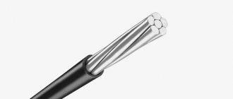
Elements of the home electrical network. Wires. Cords. CablesI present to your attention several chapters from the book “Home Electrician's Handbook”. The author of the book is S. L. Koryakin-Chernyak.
Comparison of conductor materials
Aluminum
is one of the most common materials in the manufacture of wires and cables.
Its conductivity is approximately 62% that of copper
, but due to aluminum's low density, the conductivity per unit mass is twice that of copper.
However, compared to copper, aluminum has low mechanical strength and reduced contact properties. One of the negative properties of aluminum is rapid oxidation
upon contact with air and the formation of a refractory (with a melting point of about 2000°C) oxide film on its surface.
The oxide film
does not conduct electric current well and therefore prevents the creation of good contact.
In addition, when aluminum-copper contact
a “galvanic couple” is formed, in which aluminum, subjected to electrocorrosion, is destroyed.
This leads to poor connection. Rubber
and
plastic
are used as electrical insulation . In order to save scarce wires with copper conductors, currently wires and cables with aluminum conductors are mainly used for electrical wiring.
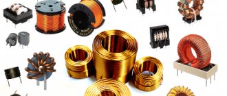
Conductor Product Differences
The available range of wires, cords and cables is extremely diverse. They differ:
- material of conductive conductors (copper, aluminum, aluminum-copper);
- cross-section of cores (from 0.75 to 800 mm);
- number of cores (single-core and multi-core, from 1 to 37 cores);
- insulation (rubber, paper, yarn, plastic);
- shells (rubber, plastic, metal),
- covers, etc.
Operating and test voltage
Each wire, cable, cord has an operating (nominal) and test voltage. These values for wires and cables characterize the electrical strength of their insulation.
Operating voltage
- this is the highest network voltage at which a wire, cable, cord can be operated.
Example.
With an operating voltage of the wire of 380 V, it is suitable for networks of 380, 220, 127, 42, 12 V. But a cord whose operating voltage is 220 V cannot be used in networks of 380 V and higher. In residential buildings, wires and cables are used for voltages of 660, 380 and 220 V. Inscriptions 660/660; 380/380 and 220/220 refer to stranded wires; they indicate the permissible voltage between adjacent conductors.
Test voltage
— determines the electrical strength margin of the applied insulation. It is significantly higher than the worker.
Influence of connected load
The installation wires must match the load being connected. For the same brand and the same cross-section of wire, loads of different magnitudes are allowed, which depend on the laying conditions and, therefore, the possibility of cooling.
Example.
Wires or cables laid openly are cooled better than those laid in pipes or hidden under plaster.
The cross-section of the current-carrying conductors is selected based on the maximum permissible heating of the conductors, at which the insulation of the wires is not damaged. The permissible values of long-term load currents for wires, cords and cables are calculated and given in the Installation Rules (PUE).
The permissible load (all other things being equal) with increasing cross-section does not increase in proportion to the cross-section, but more slowly.
Example.
With a cross section of 1 mm2, a current of 17 A is allowed. With a cross section of 1.5 mm2 - not 25.5 A, but only 23 A.
When several wires are located in a common pipe, in a hidden wiring channel, under the condition of their cooling
deteriorate, they also heat each other, so the permissible current for them must be reduced by 10...20%.
Operating temperature of wires
and cords in rubber insulation should not exceed +65°C, in plastic - +70°C. Therefore, at room temperature +25°C, the permissible overheating should not exceed a temperature of +40...45°C.
Insulation of wires and cables
Wires are manufactured with insulation for voltages of 380, 660 and 3000 V AC, cables for all voltages. In an insulated wire, the conductor is enclosed in an insulating sheath made of rubber, polyvinyl chloride or vinyl plastic.
To protect against mechanical damage and environmental influences, the insulation of some brands of wires is covered on the outside with a cotton braid impregnated with an anti-rot compound. The insulation of wires intended for laying in places where there is an increased risk of damage due to mechanical stress is additionally protected by a braid of galvanized steel wire.
You can get acquainted with certain types of cables, wires and cords produced by Russian manufacturers in the 5th issue of the magazine “I am an electrician!”
Calculation of core cross-section
Core cross-section
approximately determined by its diameter (S = 0.785d2), where d is the diameter of the core. The diameter can be measured with a caliper.
If you don’t have a caliper at hand, you can find out the diameter in the following way. 10...20 turns of the wire stripped of insulation should be wound on a thick nail, screwdriver or other rod, tightly compress the turns of the wire and measure the length of the spiral with a regular ruler. By dividing this length by the number of turns, the required diameter of the core is found.
To determine the cross-section of multi-core wires and cords, you should measure the diameter of one core, calculate its cross-section, then multiply the cross-section by the number of wires in the wire.
The exact cross-section of wires and cables with voltages up to 1000 V is determined based on two conditions.
First condition.
According to the condition of heating with a long-term design current: Iadd > Iр,
where Iadd is the long-term permissible current for the accepted cross-section of the wire or cable and the conditions for its installation. Data are provided in the PUE or reference literature; Iр - design current, A.
Second condition.
According to the condition of compliance of the wire cross-section with the protection class: Iadd > Кз x In.pl.,
where Kz is the protection factor; In.pl - rated current of the fuse link, A.
Kz = 1.25 when protecting conductors with rubber and plastic insulation in explosive and fire hazardous areas, commercial areas, etc. indoor fuses and circuit breakers; when protecting the same conductors in non-explosion and non-fire hazardous areas, Kc = 1.0.
Lighting wiring is additionally designed for voltage loss. Permissible long-term current loads on wires and cables, as well as the selection of starting and protective equipment, wires and cables for separately installed electric motors are found in reference books.
Range of standard core sections
The range of standard core sections is large: from 0.03 to 1000 mm2. We will be interested in sections from 0.35 (the minimum cross-section for connecting household electrical appliances) to 16 mm2. The cross-sections of the cores vary according to standard rows: 0.35; 0.5; 0.75; 1.0; 1.2 (copper only); 1.5; 2.0; 2.5; 3.0; 4.0; 5.0; 6.0; 8.0; 10.0; 16.0 mm2 - copper, aluminum and aluminium-copper conductors.
The rules for the construction of electrical installations (PUE) establish the minimum cross-sections of the conductors used
for buildings in mm2. They are:
- 1/2.5 mm2 - for group and distribution network lines;
- 2.5/4.0 mm2 - for the line to apartment panels with a settlement meter;
- 4.0/6.0 mm2 - for the supply network and risers.
Here the numerator indicates the cross-sections of copper conductors in mm2, and the denominator indicates the cross-sections of aluminum and aluminium-copper conductors.
According to the mechanical strength conditions of the PUE, the smallest sections S (or diameter d)
wires for branches from overhead lines to inputs into houses. They are equal: for copper wires, as well as for wires with a supporting cable of 4 mm2 in a span of up to 10 m or 6 mm2 in a span of up to 25 m. The diameter of steel and bimetallic wires should be 3 and 4 mm, respectively. The cross-section of wires made of aluminum and its alloys is 16 mm2.
At relatively low current values, the cross-section of the conductors is determined by the mechanical strength of the conductor, especially in screw contact terminals. Based on this, the cross-section of the copper core should not be less than 1 mm2, the aluminum core - 2 mm2.
Advice.
Using the cross-section of the wires, it is useful to check whether they are consistent with the maximum actual load, as well as the current of the protective fuses or circuit breaker. In this case, you need to know that the load should not exceed 1 kW per 1.57 mm2 cross-section of the core.
Connecting cords
Cord
- two or more insulated flexible or especially flexible conductors with a cross-section of up to 1.5 mm2, twisted or laid in parallel, on top of which, depending on the operating conditions, a non-metallic sheath and protective coatings can be applied.
The cords are designed to connect electrical household appliances to the electrical network (for example, table lamps, vacuum cleaners, electric shavers). Lived
Multi-wire must be used; in addition, the cord cores are connected to each other by twisting or a common braid.
Connecting cords for household electrical appliances and lamps are very diverse. They can have two, three or four copper cores with a cross-section from 0.35 to 4.0 mm2, either normal or increased flexibility.
Twin cords
used if the housing of the device (luminaire) does not require protective grounding (grounding). If grounding is required, then use a three-wire cord. The cross section depends on the current strength of the connected device (lamp).
Example.
Sections of cords used with various groups of electrical appliances:
- 0.35 mm2 - used for cords for electric shavers;
- 0.5mm2 - for table lamps, fans, TVs;
- 0.75 mm2 - for irons with a power of up to 500 W, refrigerators, vacuum cleaners.
The most common cords are:
- heat-resistant for irons and electric stoves;
- in a waterproof shell;
- in a golden and silver-colored shell for lamps with crystal elements.
Cords can be white, gray, brown, red, blue, light blue, black, yellow, ivory. The length of the cords is standardized:
- 2m - for refrigerators, irons and razors;
- 3.5 m - for washing machines;
- 6m - for floor polishers and vacuum cleaners.
Cords can be cut at one end or at both ends, and also reinforced with permanent plugs and appliance sockets.
How to choose the right wire or cable
The cross-section of the cores, depending on the load and material (copper, aluminum), is selected in accordance with the “Rules for Electrical Installations”.
Let's consider the issue of replacing wires if there is no exactly required version of the wire, cable, or cord.
Taking into account the rated voltage
You need to pay attention to the rated voltage of the wire proposed for replacement: it must be no less than the mains voltage.
Examples.
- If the wires do not extend beyond the apartment, then the rated voltage of the wire must be at least 220 V.
- If the wires go outside the apartment, then the rated voltage of the wire should not be lower than 380 V.
Accounting for core material
You need to pay attention to the material of the cores, keeping in mind that aluminum and aluminum-copper wires can always be replaced with copper ones. Copper wires cannot be replaced with aluminum and aluminum-copper wires in the following cases:
- if flexibility is required (flexible wires must be copper);
- if the wires are connected by soldering and not by screw terminals.
Accounting for core cross-section
You need to pay attention to the cross-section of the veins. It must correspond to the load in amperes, i.e. be no less than the values specified in the PUE. On the other hand, the cross-section should not be too large, otherwise the wire cannot be securely connected to switches and sockets.
But the cross-section should not be too small, since it is difficult to clamp a thin wire: it will dangle. Therefore, the smallest cross-sections of conductors for connection to screw terminals have been established: 1 mm2 for copper and 2 mm2 for aluminum wires. With a cross section of 0.75 mm2, you need to place a washer. According to the mechanical strength conditions, the cross-section of wires for air entry into the building must be no less than that indicated above.
Taking into account additional conditions
Single-wire wires can always be replaced with multi-wire (flexible) ones. In addition, it is necessary to pay attention to the compliance of the type of insulation with the installation conditions. Thus, wires intended for laying in damp rooms can be laid in dry ones, but in no case should wires intended only for dry rooms be laid in damp rooms.
Heat-resistant wires, for example, PRKA brand wire, intended for internal installation of electric stoves, cannot be replaced with “regular” wires: their insulation in the stove will simply burn.
The article uses materials from the book Koryakin-Chernyak S.L. “Home Electrician's Handbook”.
See also:
Collection of articles “Installation of electrical wiring, switches, sockets. Electrician's secrets"