Reduced (low voltage)
One of the electrical safety measures is the use of reduced voltage, taking into account the possible operation of equipment, devices, equipment. Thus, when operating all lighting equipment, a voltage of no higher than 127/220 V is used. And when working with portable power tools, as well as with hand-held portable lamps, the voltage is 36 or 42 V. In rooms with increased electrical safety, particularly dangerous and fire-explosion hazardous rooms, the voltage should not exceed 12 V.
Low voltage sources (12, 24, 36 and 42V) can be batteries, step-down transformers, frequency converters.
At the same time, the use of autotransformers and rheostats to reduce voltage is prohibited due to the connection of low- and high-voltage networks.
To reduce the danger of using step-down transformers, the secondary winding and the transformer housing are grounded or grounded.
Protective grounding, grounding
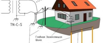
Safe work with electrical installations is ensured by grounding, grounding (in networks up to 1000V) and protective deflection.
Application area
According to GOST 12.1. 013-80 and GOST 12.1.030-80 “Electrical safety. Protective grounding, grounding", GOST 12.1.019-79 "Electrical safety. General requirements and nomenclature of types of protection,” grounding or zeroing should be performed:
- at a rated voltage of 380V and above alternating current, 440V and above direct current in electrical installation networks in any premises (including premises without increased danger);
- at a rated voltage of 36V and higher (according to GOST 12.1.013-80), 42V and higher (according to GOST 12.1.030-81) alternating current and 110V and higher direct current of electrical installations in high-risk premises and especially hazardous premises, in outdoor electrical installations;
- at any rated voltage of alternating and direct current electrical installations in all explosive conditions.
Parts of electrical installations that are subject to grounding or grounding:
— metal housings of electrical machines, transformers, apparatus, lamps, mobile electrical installations, portable electrical installations;
— frames, control panels, control rooms and cabinets, as well as removable or opening parts, if electrical equipment with a voltage higher than 42V AC or a voltage higher than 110V DC is installed on them;
— drives of electrical devices;
— secondary windings of instrument transformers;
-metal switchgear, metal small structures, metal couplings, metal sheaths and armor of control and power cables, metal sheaths of wires, electrical wiring pipes, etc.;
— reinforced concrete power transmission line supports.
Grounding of electrical equipment
According to its functional purpose, grounding is divided into three types - working, protective, lightning protection grounding.
Working grounding includes grounding of the neutrals of power transformers and generators, dead or through an arc suppression reactor.
Protective grounding is performed to ensure the safety, first of all, of people.
Lightning protection grounding serves to drain lightning current into the ground from protective arresters and lightning rods (rod or cable).
Protective grounding must fulfill its purpose throughout the year, while grounding and lightning protection - only during thunderstorms.
Purpose of protective grounding
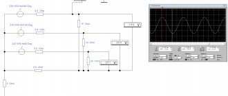
. Protective grounding is intended to eliminate the risk of electric shock to people when they come into contact with metal parts of electrical equipment that are energized. The operating principle of protective grounding is to reduce touch and step voltages caused by a short circuit to the body of electrical equipment to a safe level. This is achieved by reducing the potential of the grounded equipment due to the low resistance of the ground electrode, as well as by equalizing the potentials of the base on which the person is located and the grounded equipment by raising the potential of the base to the level of the potential of the grounded equipment.
Protective grounding is a parallel connection to the electrical circuit of a grounding conductor with a significantly lower resistance Rз
(Fig. 3.3.4.6)
In networks with voltages up to 1000V, the resistance of the grounding device should be no more than 4 ohms, for voltages above 1000V - no more than 0.5 ohms.
With this inclusion in the electrical circuit, the current passing through the person will be equal to:
(3.4.21)
where, Rr
– human body resistance, Ohm
Itot —
total passing current through two ground electrodes (human body and ground electrode), Ohm;
Rtotal –
total resistance of grounding conductors, Ohm.
Fig. 3.4.6 Protective grounding: a – grounding diagram of the electrical equipment housing; b-equivalent electrical circuit
(3.4.22)
(3.4.23)
After substituting the values of Rtot
and
Itot
into formula / 3.4.21/ we get
(3.4.24)
Example.
Determine the magnitude of the damaging current when a person is single-phase connected to a three-phase network with an isolated neutral.
Let's assume that the resistance of the floor and shoes: Rп = Rоb = 0 Ru = 3000 Ohm
In the absence of grounding, the damage current:
A
If there is a protective ground:
A
As you can see, the damage current in the presence of a grounding device is significantly less than the holding one.
Protective grounding is used in electrical installations with voltages up to 1000V AC with an isolated neutral or with an isolated output of a single-phase current source, as well as electrical installations with voltages up to 1000V in DC networks with an isolated midpoint.
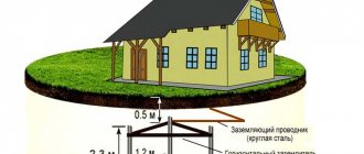
Grounding of installations consists of connecting their metal parts (normally not energized) to the ground with a ground electrode having low resistance to current flow.
The grounding device consists of grounding conductors, grounding bars and wires connecting the housings of electrical installations with grounding conductors.
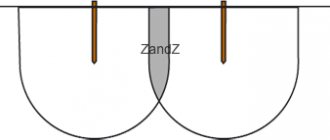
Depending on the location of the grounding conductors relative to the grounded equipment, grounding devices are divided into remote and loop (Figure 3.4.7). External grounding switches
the grounding device is placed at some distance from the grounded equipment.
A loop grounding
device provides a higher degree of protection, since grounding conductors are located along the contour of all grounded equipment.
Fig. 3.4.7 Remote (a) and loop (b) grounding:
1-electrodes (grounding electrodes); 2 currents (buses); 3-electrical installations
In practice, grounding is carried out in the following order:
— a grounding device (artificial or natural) is selected;
— the grounding device is calculated;
-separate electrodes (grounding electrodes) are combined into one common grounding device;
— electrical installation housings are connected to a grounding device;
- documentation is drawn up for acceptance of the grounding device into operation.
When choosing a grounding device, natural grounding conductors are often used, which are pipelines laid in the ground and having good contact with the ground, steel pipes of electrical wires. During the construction of industrial buildings, metal building frames can be used as natural grounding conductors.
Pipelines for flammable liquids and explosive gases must not be used as grounding conductors. Metal and reinforced concrete structures, when used as grounding devices, must form a continuous electrical circuit through the metal (in reinforced concrete structures, embedded parts must be provided for connecting electrical and technological equipment).
When using reinforced concrete foundations as grounding conductors, the current spreading resistance of the grounding device is determined by the formula
(3.4.25.)
where Qe is the specific equivalent electrical resistance of the earth, Ohm • m;
s is the area limited by the perimeter of the building, m2.
One of the electrical safety measures is the use of reduced voltage, taking into account the possible operation of equipment, devices, equipment. Thus, when operating all lighting equipment, a voltage of no higher than 127/220 V is used. And when working with portable power tools, as well as with hand-held portable lamps, the voltage is 36 or 42 V. In rooms with increased electrical safety, particularly dangerous and fire-explosion hazardous rooms, the voltage should not exceed 12 V.
Low voltage sources (12, 24, 36 and 42V) can be batteries, step-down transformers, frequency converters.
At the same time, the use of autotransformers and rheostats to reduce voltage is prohibited due to the connection of low- and high-voltage networks.
To reduce the danger of using step-down transformers, the secondary winding and the transformer housing are grounded or grounded.
Protective grounding, grounding
Safe work with electrical installations is ensured by grounding, grounding (in networks up to 1000V) and protective deflection.
Application area
According to GOST 12.1. 013-80 and GOST 12.1.030-80 “Electrical safety. Protective grounding, grounding", GOST 12.1.019-79 "Electrical safety. General requirements and nomenclature of types of protection,” grounding or zeroing should be performed:
- at a rated voltage of 380V and above alternating current, 440V and above direct current in electrical installation networks in any premises (including premises without increased danger);
- at a rated voltage of 36V and higher (according to GOST 12.1.013-80), 42V and higher (according to GOST 12.1.030-81) alternating current and 110V and higher direct current of electrical installations in high-risk premises and especially hazardous premises, in outdoor electrical installations;
- at any rated voltage of alternating and direct current electrical installations in all explosive conditions.
Parts of electrical installations that are subject to grounding or grounding:
— metal housings of electrical machines, transformers, apparatus, lamps, mobile electrical installations, portable electrical installations;
— frames, control panels, control rooms and cabinets, as well as removable or opening parts, if electrical equipment with a voltage higher than 42V AC or a voltage higher than 110V DC is installed on them;
— drives of electrical devices;
— secondary windings of instrument transformers;
-metal switchgear, metal small structures, metal couplings, metal sheaths and armor of control and power cables, metal sheaths of wires, electrical wiring pipes, etc.;
— reinforced concrete power transmission line supports.
Grounding of electrical equipment
According to its functional purpose, grounding is divided into three types - working, protective, lightning protection grounding.
Working grounding includes grounding of the neutrals of power transformers and generators, dead or through an arc suppression reactor.
Protective grounding is performed to ensure the safety, first of all, of people.
Lightning protection grounding serves to drain lightning current into the ground from protective arresters and lightning rods (rod or cable).
Protective grounding must fulfill its purpose throughout the year, while grounding and lightning protection - only during thunderstorms.
Purpose of protective grounding
. Protective grounding is intended to eliminate the risk of electric shock to people when they come into contact with metal parts of electrical equipment that are energized. The operating principle of protective grounding is to reduce touch and step voltages caused by a short circuit to the body of electrical equipment to a safe level. This is achieved by reducing the potential of the grounded equipment due to the low resistance of the ground electrode, as well as by equalizing the potentials of the base on which the person is located and the grounded equipment by raising the potential of the base to the level of the potential of the grounded equipment.
Protective grounding is a parallel connection to the electrical circuit of a grounding conductor with a significantly lower resistance Rз
(Fig. 3.3.4.6)
In networks with voltages up to 1000V, the resistance of the grounding device should be no more than 4 ohms, for voltages above 1000V - no more than 0.5 ohms.
With this inclusion in the electrical circuit, the current passing through the person will be equal to:
(3.4.21)
where, Rr
– human body resistance, Ohm
Itot —
total passing current through two ground electrodes (human body and ground electrode), Ohm;
Rtotal –
total resistance of grounding conductors, Ohm.
Fig. 3.4.6 Protective grounding: a – grounding diagram of the electrical equipment housing; b-equivalent electrical circuit
(3.4.22)
(3.4.23)
After substituting the values of Rtot
and
Itot
into formula / 3.4.21/ we get
(3.4.24)
Example.
Determine the magnitude of the damaging current when a person is single-phase connected to a three-phase network with an isolated neutral.
Let's assume that the resistance of the floor and shoes: Rп = Rоb = 0 Ru = 3000 Ohm
In the absence of grounding, the damage current:
A
If there is a protective ground:
A
As you can see, the damage current in the presence of a grounding device is significantly less than the holding one.
Protective grounding is used in electrical installations with voltages up to 1000V AC with an isolated neutral or with an isolated output of a single-phase current source, as well as electrical installations with voltages up to 1000V in DC networks with an isolated midpoint.
Grounding of installations consists of connecting their metal parts (normally not energized) to the ground with a ground electrode having low resistance to current flow.
The grounding device consists of grounding conductors, grounding bars and wires connecting the housings of electrical installations with grounding conductors.
Depending on the location of the grounding conductors relative to the grounded equipment, grounding devices are divided into remote and loop (Figure 3.4.7). External grounding switches
the grounding device is placed at some distance from the grounded equipment.
A loop grounding
device provides a higher degree of protection, since grounding conductors are located along the contour of all grounded equipment.
Fig. 3.4.7 Remote (a) and loop (b) grounding:
1-electrodes (grounding electrodes); 2 currents (buses); 3-electrical installations
In practice, grounding is carried out in the following order:
— a grounding device (artificial or natural) is selected;
— the grounding device is calculated;
-separate electrodes (grounding electrodes) are combined into one common grounding device;
— electrical installation housings are connected to a grounding device;
- documentation is drawn up for acceptance of the grounding device into operation.
When choosing a grounding device, natural grounding conductors are often used, which are pipelines laid in the ground and having good contact with the ground, steel pipes of electrical wires. During the construction of industrial buildings, metal building frames can be used as natural grounding conductors.
Pipelines for flammable liquids and explosive gases must not be used as grounding conductors. Metal and reinforced concrete structures, when used as grounding devices, must form a continuous electrical circuit through the metal (in reinforced concrete structures, embedded parts must be provided for connecting electrical and technological equipment).
When using reinforced concrete foundations as grounding conductors, the current spreading resistance of the grounding device is determined by the formula
(3.4.25.)
where Qe is the specific equivalent electrical resistance of the earth, Ohm • m;
s is the area limited by the perimeter of the building, m2.
Definition of the concept and classification of voltage classes
Note 1
Depending on the classification of electrical networks, the voltage classes will also change. Modernization of electrical networks by energy companies leads to an increase in voltage class. This is due to the desire to reduce costs and losses when transporting electrical energy directly to the consumer.
Are you an expert in this subject area? We invite you to become the author of the Directory Working Conditions
The transfer of electrical power (if the voltage is low) leads to large losses due to the high values of the flowing current. The formula $\Delta S=I^2R$ shows the power loss depending on the flowing current and line resistance. Reducing losses is facilitated by reducing the flowing current: for example, if you reduce the current by 2 times, power losses will decrease by 4 times.
The formula for total electrical power is written as follows:
$S=IU$
Transmitting the same power at a reduced current will require increasing the voltage by the same amount. It is therefore advisable to transmit large powers if the voltage is high. The construction of high-voltage networks, at the same time, is accompanied by many technical difficulties. Moreover, direct consumption of electrical energy at high voltage will be quite problematic for the end user.
This contributed to the division of networks into sections according to voltage class (i.e. level). Three-phase networks, whose task is to transmit large powers, have the following voltage classes:
Finished works on a similar topic
Course work Electrical voltage classes 480 ₽ Abstract Electrical voltage classes 260 ₽ Test work Electrical voltage classes 250 ₽
Receive completed work or specialist advice on your educational project Find out the cost
- over 750 kV (1150 and 1500) (class is considered ultra-high;
- below 750 kV (500 kV, 400 kV) (this is a European standard, the class itself is called ultra-high);
- 330 kV, 220 kV, 150 kV, 110 kV – high voltage class;
- 35 kV, 33 kV, 20 kV - medium first voltage class;
- 10 kV, 6 kV, 3 kV – medium second voltage class;
- 24 kV, 22 kV, 18 kV, 15.75 kV (considered the most common) - voltage class at generator terminals;
- 0.69 kV (European industrial standard), 0.4 kV (main standard), 0.23 kV, 110 V (old European standard) and below - low voltage class.