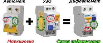
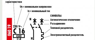
Identification of damaged components in electrical networks and systems is carried out using protection. Such protection has a selective effect. Thanks to this feature, reliable and long-term operation of electrical equipment is possible, as well as the safety of its maintenance by technical personnel.
Selectivity
Main tasks of selective protection
Selectivity is a process that means selection (selection). This term is applicable to different industries and areas of human activity. For example, in chemistry, when chemical reactions occur, they talk about the selectivity index. In this case, the selectivity of chemical transformations is considered.
As for a person, his perception of the world around him, the choice of information, as well as its memorization are selective.
What is selectivity in electrical engineering, and why is it needed?
The tasks of electrical selective protection include:
- guaranteeing the safety of equipment and operating personnel;
- instantly identifying the location of the fault and disconnecting only the faulty section;
- reducing the negative effects of the accident on other components and parts of electrical appliances;
- minimizing damage to the faulty area;
- guaranteeing maximum continuity of operation of the electrical system;
- achieving ease of operation of electrical equipment.
In addition, selectivity reduces the consequences of short circuits and the load on the device.
Main functions
So, the main functions of selective protection are:
- ensuring the safety of electrical appliances and employees;
- instant detection and shutdown of the power zone in which the breakdown occurred, without other shutdowns that will stop the supply of electricity in places where the equipment is stable;
- reducing the impact of negative consequences on other parts of electrical mechanisms;
- reducing the load on component installations and preventing breakdowns in the faulty area;
- ensuring the highest possible uninterrupted power supply of high quality;
- ensuring continuity of the work process;
- providing qualified support in the event that the protection responsible for the trip itself becomes faulty;
- support for optimal operation of the installation;
- ensuring ease of operation and cost-effectiveness.
Absolute and relative selectivity of protection
Considering in detail what selectivity is, there are two types of selective action.
Features of differential protection of power equipment
According to the degree of selectivity, protection is divided into:
- absolute;
- relative.
The blowing of fuses in the exact circuit where the short circuit occurred is called “absolute protection”.
The tripping of a circuit breaker close to where the fuse failed is called "relative protection".
Attention! We can say that absolute selective protection protects against internal (own) short circuits, and relative selective protection protects against external (neighboring) and internal short circuits at the same time.
Relative and absolute selectivity of protection
Scheme of operation of the machines
An idea of what selectivity is can be obtained by considering the operating diagram of a home electrical panel.
In the event of a short circuit in the kitchen or other room, only the protective device that belongs to this circuit should operate. The input machine will not turn off and will conduct electricity to other areas. If for some reason the kitchen switch does not work, then the input circuit breaker will control the fault, cutting off power to all electrical circuits.
Overcurrent selectivity
First of all, let’s define what supercurrents are. These are indicators of electric current that exceed the parameters of the rated current. This primarily concerns strength and tension.
Therefore, selectivity in this case coordinates the operation of several devices according to established indicators. This takes into account the fact that each device has its own response range. The rest do not respond to changes in network parameters. That is, the following scheme is obtained. There is a certain selectivity between two circuit breakers that are located in series in the circuit.
So, on the load side, the switch breaks the circuit. And on the current supply side it is in a closed state. That is, the latter provides current to all other sections of the circuit. This selectivity is called partial. It is this that ensures that the installation is not fully loaded if it is necessary to eliminate problems (short circuit or overload) in one area. At the same time, the rest are working as normal.
There is complete selectivity, this is when the circuit breaker at the input, that is, on the supply circuit, is triggered. In this case, the second switch located on the load does not turn off. In principle, this makes no sense, because the electrical circuit is completely turned off in this case.
But here it is necessary to clarify that there is a certain relationship between the rated current and the overload current. Full selectivity ensures any overcurrent value. But in the partial mode, the action of the two switches occurs completely differently. To do this, the selectivity of each switch is taken into account, which depends on the strength of the overcurrent. In this case, the current strength that turns off the circuit breaker (selective RCD) at the load should be less than at the power supply.
There are two main reasons why it is necessary to disconnect an electrical circuit:
- Network overload.
- Short circuit.
Firstly, the overload zone is larger and more frequent. Secondly, to protect against this cause, mainly thermal protection is installed in the circuit.
The short circuit zone is a range of current values that exceeds the rated current by eight to ten times. Therefore, in this case magnetic protection is used. Such an event is unlikely in electrical circuits that are assembled correctly. But, as they say, God protects those who are careful.
Types of selective connection schemes
Protective equipment is divided into several types based on selectivity. These include the following types of protection:
- full;
- partial;
- current;
- temporary;
- time-current;
- energy.
Overcurrent protection
Each of them needs to be discussed separately.
Full and partial protection
With such circuit protection, the devices are connected in series. In the event of an overcurrent, the circuit breaker that is closest to the fault will operate.
Important! Partial selective protection differs from full selectivity in that it operates only up to the set overcurrent value.
Current selectivity type
By arranging the magnitudes of currents from source to load in descending order, current selectivity is ensured. The main measure here is the limiting value of the current tag.
For example, starting from the power source or input, circuit breakers are installed in the sequence: 25A, 16A, 10A. All machines can have the same response time.
Important! There must be a high circuit resistance between the machines. Then they will have effective selectivity. They increase resistance by increasing the length of the line, including sections with a wire of smaller diameter or inserting a transformer winding.
Current selectivity
Time and time-current selectivity
What does time selective protection mean? A feature of this design of a relay protection circuit is that it is tied to the response time of each protective element. Automatic switches have the same current parameters, but have different time delays when triggered. The response time increases as you move away from the load. For example, the closest one is designed to operate after 0.2 s. If it fails after 0.5 s. the second one should work. The operation of the third circuit breaker is calculated after 1 second in case of failure of the first two.
Temporal selectivity
Time-current selectivity is considered very difficult. To organize it, you need to select devices from groups: A, B, C, D. Group A has the highest protection (used in electrical circuits). Each of these groups has an individual response to the magnitude of the electric current and the time delay.
Energy selectivity of machines
This protection is due to the properties of the switches provided by the manufacturer. Fast response - before short-circuit currents reach their maximum. Milliseconds count; it is very difficult to coordinate such selectivity.
Energy selectivity
What is zone selectivity
The determination of this coverage by selective network protection is related to the peculiarities of its construction. This is a rather expensive and complicated method. As a result of processing the signals coming from each switch, the fault zone is determined, and shutdown occurs only in it.
Information. To provide such protection, additional power is required. The signal from each switch is sent to the control center. Shutdowns are made by electronic releases.
It is most rational to use such circuits in industrial enterprises, where systems have high values of short-circuit currents and significant operating currents.
Example and graph of zone selectivity
What are time-current characteristics?
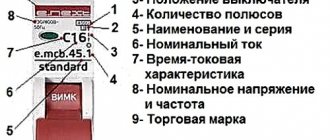
Hoping that the reader is prepared, I will be brief and talk only about what relates to the topic of the article. The letters B, C and D are the main characteristics of the electromagnetic release. The letter indicates the range of instantaneous tripping currents. At the beginning of this range, the EM release should not operate , within the range it may operate , and at an overcurrent equal to the upper end of the range (or more), it should operate . The range limits can be illustrated using simplified graphs for three AVs with the same rated current of 10 A, but with different shutdown characteristics:
Graphs for one rated current and different tripping characteristics
The thermal release graph, shown as a smooth thick line, is the same for all three circuit breakers. But the ranges of instantaneous tripping currents (shaded in blue) are different.
With an overcurrent of up to 11.3 A, our three switches should never turn off. As the current increases, the turn-off time decreases down to seconds, and when operating in the so-called short-circuit current zone, the turn-off time can be tens or even a few milliseconds. All currents that exceed the marked ranges shall result in instantaneous tripping.
Details about the time-current characteristics of circuit breakers can be found in GOST IEC 60898-1-2020.
Calculation of selectivity of machines
When considering the question of what selectivity is, it is necessary to have an idea of how it is calculated. Calculations come down to the correct selection of a protective device, in particular an automatic machine.
Selectivity for machines located close to the power source must satisfy the following condition:
Is.o.last ≥ Kn.o.* Ik. previous,
Here:
- Is.o.last – the value of the current that triggers the protection;
- Kn.o. – shutdown reliability coefficient;
- I part previous – short-circuit current at the end of the protection section.
In the case of time dependence, the following formula is used to calculate selectivity:
Ts.o.last ≥ Tk.prev.+ ∆T,
Where:
- Tс.о.last and Тк.prev. – time intervals through which cut-off switches operate;
- ∆T – selectivity time point.
The selection of automatic switches for calculations is carried out according to the tables.
Machine selectivity table
Determination of selectivity of circuit breakers
The definition of "selectivity" implies a protective mechanism and smooth functioning of certain devices consisting of individual parts connected in series with each other. Often, such devices are various types of circuit breakers, fuses, RCDs, etc. The result of their work is to prevent the combustion of electrical mechanisms in the event of threats.
What does the device look like?
Note! The advantage of this system is its ability to turn off only the necessary areas, while the rest of the system remains in working order. The only condition is that the protective devices are consistent with each other.
Zone defense scheme
Principle of logic
To implement circuits using this principle, digital relays are needed. The relays are connected to each other by a twisted pair line, a fiber optic cable, or via a telephone line (using a modem). With the help of such lines, information is received (transmitted) to the dispatch console from different objects and between the relays themselves.
The principle of logic in a radial network
The given Picture 9 explains the principle of operation of the logic. Each of the 4 digital relays uses a current setting equal to the most recent sensitive stage. This stage has an operating time of 0.2 s. Logical selectivity implies the possibility of blocking the relay with a LO (logical standby) signal. This signal is supplied through the channel from the previous protection relay. Each of the relays can transmit such signals in transit.
As can be seen from the figure, during a short circuit at point K1, all other relays, from the LO signal supplied by relay K1, will be on hold. Relay K1 will operate and shut down. In the event of a short circuit at point 2, relay K4 will operate in the same way.
Such schemes for constructing logical control are demanding on the reliability of communication lines between elements.
Current selectivity
This type of selective protection is installed in each electrical circuit at its beginning. If a short circuit occurs in an electrical network consisting of these circuits, the current increases according to its impedance. In this case, the inductance limits the rate of current rise and there is a certain minimum value. This value is the protection threshold.
At the same time, protective devices can operate at slightly lower current values, if necessary. But the magnitude of the triggering current must be in the range of current values, which will be greater than in the case of a short circuit outside the protection coverage area. An example of current protection for a circuit with a transformer connected between cable power lines is shown in the image below:
The advantage of current selectivity is the ability to respond only to faults within the protected area and in connection with the consumer, excluding accidents outside the protected area. It is characterized by fast response, low cost and circuit simplicity. This is its advantage. The disadvantage is the difficulty of adjusting the selectivity of sequentially installed protection devices when they are located in neighboring areas due to the similarity of process parameters determined by emergency situations.
Directional principle
The arrangement of the machines and the further sequence of their operation are guided by the direction of the current. To do this, using the voltage vector, a point is specified, relative to which this vector receives a phase shift. According to this principle, the relay will be sensitive to both current and voltage. Such a circuit can be installed in both a switchable zone and a zone that cannot be switched off.
RCDs and switches are connected according to the directional principle
Important! To implement such circuits, voltage transformers are needed to use them to determine the direction of the current.
In the above figure, you can see that the protective device D1 and the circuit breaker it controls will respond to a short circuit at point 1, but not to a short circuit at point 2.
What is the current limit in selectivity?
Modular circuit breakers have a parameter called current limit class, which actually reflects the speed of the electromagnetic release. It would seem that the faster the better, but for selectivity it makes sense to install a group machine with a slower response, so that during a short circuit on any outgoing line it does not work together with the machine of this line.
Overload zone
Although there is no guarantee that a machine with a lower current limit class will work slower than one with a higher one. It is unlikely that all manufacturers adhere to the same standards for this parameter. But if you can install a machine with a higher current limit class on the output line, then it’s worth doing.
You might be interested in Calculating cross-sectional area
Principle of differentiation
It is used where circuits with high power consumers are used. These consumers include:
- electric motors and generators;
- power cables;
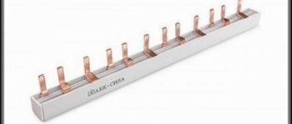
- bus assemblies;
- transformers and other converters.
In this solution, deviations of the phase and amplitude parameters of the current at various points are used. A deviation of such values at point A and point B, in section AB, is considered an emergency, and the equipment shuts down. The use of current transformers allows filtering from various extraneous electromagnetic processes.
The protection is triggered only in the AB section if IA>IB.
Differential selective protection of powerful equipment
Protection created according to the differential principle can be of two types: longitudinal and transverse.
CS-CS.Net: Laboratory of the Electroshaman
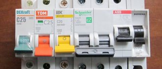
ABB module layouts
I’m making a small note, because it’s high time for it to appear: I got carried away telling the same thing in the comments. And I’ll warn you right away: I’m learning myself (and I’m happy to do this all my life, exploring the world), so I haven’t yet deeply understood how it all works. But I understood enough to explain to myself and everyone on the fingers why in some cases the machines will operate simultaneously during a short circuit, and not one after another. The science, the field of calculations and the very property of ensuring that in emergency situations only the lower-level machine in the shield is cut off is called selectivity. You can say “selectivity is observed”, or you can “calculate selectivity”, or you can say “selective machine”.
What I want to explain is actually simple and stupid. But for some reason many people stumble at this point. We are interested in why in the panel version “a 50A input circuit breaker and a 16A circuit breaker in the panel” only the small 16A circuit breaker will not always be switched off (for example, when there is a short circuit in the socket), but often also the entire input circuit breaker. There is also all sorts of mysticism around this, like around an RCD. On the forums they also fight on the topic “But I have 50A at the input and everything works well” or “And I have 32A at the input and also knocks out 16A first, that’s because I have an IEC” or “And I have 50A knocks out and 10A knocks out at the same time and I'm tired of choosing manufacturers so that it doesn't knock out; I installed another 40A circuit breaker in the apartment switchboard for input - so now it knocks out all three.” And because of this, people begin to think in a slightly wrong direction. For example, he wants to put a circuit breaker of category D on input (here you can remember about these letters), but it didn’t work. And he doesn’t understand that such a machine will not be able to cut off the input cable of the shield if something happens.
But in fact, everything revolves around one simple thing: SHORT CIRCUIT CURRENT. It is precisely because of this that we sometimes maintain selectivity, sometimes we don’t, and sometimes all the machines in the chain work, sometimes only the group one. Or even the group one may not work if it is chosen incorrectly. Let's try to figure it out? For those who are interested even more closely, I found the ABB handbook on selectivity. Here it is: ABB_SelectivityGuide.pdf (3.5 MB).
Let's remember simple physics from high school. If anyone remembers, there were all sorts of boring problems like “In a circuit with a 12-volt power supply there are three resistances with nominal values of 10, 3 and 8 ohms. Calculate the current in the circuit and the voltage at each resistance.” All these problems were boring because they were abstract. In general, abstract learning is an ass. It is believed that it should develop breadth and associative thinking, but in reality it kills them: why the hell remember something if you don’t understand why you remember it? But when they explain it to you with an example, and then say “act on the same principle,” then learning is a hundred times easier and more interesting.
So let's try to figure out what we will have in the circuit if a short circuit occurs. First we need to understand what this “chain” is for us and what it is like. And this is where the most interesting thing lies, which everyone forgets about. The fact that the power supply circuit of our outlet starts from the power substation (TP - transformer substation or some type of fool)! Here's what it might look like:
Power supply diagram for a socket from a substation
If you understand all this, then you will immediately dismiss a bunch of idiots who, for example, force two machines to be installed in the entrance panel of a country house: one before the meter, and the other after. And they explain this as “well, when there is a short circuit, the current will not reach the meter, this machine, which is located after the meter, will turn it off and will not allow it to continue.” This is all complete nonsense and insanity. This is how the current will flow: from the substation, along the cable that powers the house, through the panel room of the house, through the floor riser, through the floor panel, the input circuit breaker there, through the cable to the apartment switchboard, through its wires, through the circuit breaker in it, through the socket cable - and to the outlet itself and to the point of short circuit.
Short circuit current path (from substation)
So we got our physics problem. After all, the cables have internal resistance, and the substation is capable of delivering a very large current (imagine - a powerful transformer in it, which powers several houses, is short-circuited). And this current flows through all the cables and wires, and is limited only by the internal resistance of these cables.
What does physics tell us about serial connection? She says that the total resistance of the circuit will be equal to the sum of the individual resistances, and the current... but the current will be the SAME in all sections of this circuit! That is, we get this: the current that will flow from the substation to the outlet (through all the switchboards and machines in them) will depend on:
- Substation power: the larger it is, the lower the resistance of the transformer windings themselves and the greater the TKZ.
- Cross-sections of supply cables: the larger the cross-section of the cable (and it depends on the current that we will drive through it), the lower its resistance and, again, the greater the TKZ.
- Cable lengths. The larger it is, the greater the resistance of the cables and the less TKZ.
There are certain methods for calculating all this. And in some cases (for all kinds of offices and industrial garbage) this TKZ MUST be considered. I haven’t studied this point and I want to take a lesson from comrade Alexiy someday. In any case, for this calculation you need to either get to the head of the building’s engineer, who must pull up the design of this building and pull out the data from there. And if he’s too lazy, can’t do it, or doesn’t have it, then he has to upload all the data to the cables, to the model of the transformer in the substation, and calculate everything himself.
TKZ value and breaking capacity.
First, let's chat about this moment. Everyone knows that there are some numbers in the square on the machine. Usually this is “6000” or “4500” for budget series. This is the number of short circuit current in amperes (our same TKZ), which the machine can normally and regularly turn off many, many times. Can you imagine how interesting and cool: a small machine 17.5 mm wide can extinguish hellish plasma with a current of up to 6000 amperes!
Moreover, it turns out that there is a rated breaking capacity and a limiting capacity. The circuit breaker must turn off the current rated breaking capacity three times in a minute and at the same time must continue to operate as usual. And at the limit, you don’t have to turn it off three times in a minute and continue to work. This knowledge led me to an interesting thought: in some forums about IEK and similar Chinese machines they wrote that they turn off the circuit three times and then break down. So, isn’t someone cheating with these parameters and passing off the maximum ability as the nominal one?
Let's return to TKZ. So in some cases it can be such a bummer. For example, we rent a room in some old factory. The substation there is powerful, because it is designed for a bunch of infernal machines. Let's say we were allocated a 50A machine. BUT our line is long (for example, 100 meters from the switchboard shop), and instead of a cable with a cross-section of 10..16 squares, we must lay a cable with a cross-section of 35 squares, so that due to the long line we do not have voltage losses (these sections are taken from the bulldozer for an example).
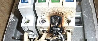
And because of this, it may turn out that due to the large cross-section of the cable we get a large TKZ. And sometimes an ordinary module may EVEN not be enough: it simply will not pass the breaking capacity. That is, an ordinary 50A circuit breaker will simply EXPLODE when shorted, and will not turn off the input. In this case, we will need circuit breakers with greater breaking capacity. For example, there are machines of the S200P series, which have 10 kA (or difautomatic machines of the DS202C series, also 10 kA) or the S800 series (10..25 kA). And in some cases it will be necessary to install a machine in a molded case (20..100 or higher kA), for example TMax and TMax XT.
Here, too, there is a cunning idea from the manufacturers: for example, you simply cannot stuff the cable from our example with 35 square meters into a regular 6 kA module. And you don’t need to cut the cable cores for this! It’s better to think about why it doesn’t fit there: maybe it was done for a reason? Therefore, when we assembled the board in CITY, even though we needed a 40A input circuit breaker, the cable we had was 70 square meters long. And that’s why, for reinsurance (because the data about TKZ could not be extracted from anyone), a machine with a high breaking capacity was installed. Wow!
Why is selectivity not always observed when closing?
Well, now let's return to our chain of machines. Let us have an introductory circuit breaker for 63A (let’s put in MORE, hehe, THE SHOP DIDN’T KNOCK OUT) and a circuit breaker for the 16A outlet. Let's apply our knowledge that the TKZ depends on all, all circuits, starting from the substation, and that at the moment of closing the TKZ will be the same EVERYWHERE (the circuit is sequential!).
Again. Due to the fact that we have a series circuit, the TKZ at the moment of closure is the same EVERYWHERE: in the substation transformer, in the riser wires, and in the wires to the outlet.
What happens? I don’t know exactly which TKZ are in which houses, but I know that in some, during a short circuit, both the 16A circuit breaker and the 63A input are cut, and in some – not. Therefore, let’s take the value from the bullshit so that the example fits. Let TKZ be equal to 600A . This means that 600A went through our 63A input circuit breaker and through the circuit breaker to the 16A outlet.
Short circuit current values and circuit breakers
Attention, now there will be a trick! In a series circuit, the current is the same everywhere. This means that at the same second 600A passed through the 16A circuit breaker. And he is absolutely guaranteed to turn off the line (even if it is D16, then at currents of 160..320A it will work). And at the same moment in time, the same 600A goes through the input machine at 63A. C63 will operate in the range of 315..630A, and our current of 600A falls within these limits. And therefore, the 63A input circuit breaker also, quite honestly, MUST work.
Moreover, if you plug in group circuit breakers of category B, then nothing may change: the current still flows simultaneously through the entire chain of two machines, and that’s all. The maximum we can count on is that the external machine will have time to operate faster, open the circuit, and the input machine will not have time to complete its operation. Or maybe he will have time.
That's how this trick works. Just? Yes, it’s terribly simple and logical. But it was hard for even me to understand. More precisely, it was difficult for me to explain to others. I repeat once again: in some cases, the TKZ is so large that it is enough for both machines to work. Let's collect conclusions and different options:
- We must select the input machine according to the allocated power and the cross-section of the input cable. We won't be able to install it BIGGER: the input cable won't hold it.
- We may not be able to replace the category of the input machine (for example, plug in D): there is a risk that such a machine will simply not turn off when the input is actually closed - there is not enough TKZ value for this.
- If the riser is rotten, the wires are weak and the substation is old (or just the line is very long), then in some cases the TKZ may be very low (yes, at least 100-150 A), and it simply will not be enough to trigger a category C machine. And then It is necessary to install machine guns of category B so that they can work. Or they gave me such hope =)
I have not yet figured out how to design, take into account and calculate all this, as I already wrote. There are special programs that can build response curves for each specific machine and superimpose them on each other. If these curves overlap each other, then the machines can operate simultaneously. And if they don’t overlap, then everything will be fine with selectivity. And in the module catalogs there are special tables that show at which TKZ which machines can be selective with each other. In the example below, I took a machine gun on C63A (red curve), B16 (blue curve), C16 (pink dotted curve).
ABB Curves program for drawing curves
And it seems like these graphs show that with TKZ up to ~500-600A (the scale is logarithmic), there will be selectivity. And with a TKZ of 1 kA, it won’t do a damn thing at all. This is how you can imagine it. This is something I still want to learn.
What to do?
Nothing! There are two options: one is complex, and the second is expensive, but brutal. A difficult option is to raise the document and calculate the TKZ on the line. And after that, see what can be plugged into the input so that the allocated power is not exceeded and selectivity is obtained. Or just buy an ABB S750DR . They got confused and specially developed a cunning series of machines that have a delay in operation to give time to the usual module to cut off.
These machines are 1.5 times larger than usual (here is a link to the post with photos) and they need to be left with more free space at the top and bottom of the rack. But if you take such a 16A circuit breaker and a regular 16A circuit breaker, then in case of a dead short circuit (two nails in the socket), the normal one will still work first. And if you shorten the line on the S750DR itself, it will work.
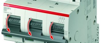
Selective automatic machine ABB S750 DR and conventional module
The main problem that happens is selectivity on a three-phase input with a 25A input circuit breaker - the same 15 kW of three-phase power. FUCK you will select it with a regular module. ONLY the S750DR will help here, and nothing else. And you need to decide what is better: running outside during a short circuit, or installing the S750DR, but being afraid that it might be stolen from a street billboard.
This is the method I came up with:
- I always assemble single-phase shields on UZOshkas and category B machines. On a high-rated input machine, this may result in an attempt to invent selectivity using the “B may have time to work before C” method, and on a weak riser (after all, single-phase input occurs in old houses with gas and rotten risers), a category C machine may not work at all.
- I almost always assemble three-phase shields on difavtomats (during the crisis I gave birth to a budget scheme, but diffs rule), and I use their category C, because on three phases the line is most often new, TKZ for C10..C16 is enough, and with this rating the input A category B machine gun won’t help at all anyway. Yes, and diffs and two-pole circuit breakers of category C are easier to obtain than diffs of category B.
- I try to create as few chains of slot machines as possible. This is also why I do not duplicate the input machine in the apartment switchboard, but put only a switch there, leaving the following chain: the input machine in the switchboard on a pole or in the floor switchboard and immediately the group breakers of the outgoing lines. And all sorts of sales freaks with “let’s put a machine before the meter and after the meter” ruin everything!
And remember that the chain “On stairs 63A, in apartment 50A” will hardly help. Only if you are lucky and the TKZ is on the border of the operation of these two machines. These are the pies!
Selectivity map and rules for its creation
The diagram of the approved sample, on which all current parameters of protective devices and devices are plotted, indicating the common power source, is carried out on a scale convenient for viewing. This is a selectivity map. It ensures maximum use of the protective qualities of circuit breakers. All processes possible during operation are displayed graphically.
The following must be included on the map:
- places of important calculation points;
- protective characteristics of automatic circuit breakers and possible short circuits, while their min and max values are indicated.
This map serves as the basis for compiling a table for the selection of protective devices. In addition, the map allows you to evaluate the overall protective selectivity and provides complete information about the mutually agreed upon settings of all machines.
The map is constructed along axes. The abscissa axis represents current values, and the ordinate axis represents time values.
For your information. Other types of characteristics can be applied to the axis. Each scheme includes the parameters of two or three machines. The construction of such maps can be done using a computer program.
An example of a selectivity map made using the program
Properly executed selective protection allows you to preserve equipment. When a specific section is turned off, it allows you to turn the power back on using an automatic transfer switch (ATS) and minimize equipment downtime and interruptions in the supply of electricity to consumers.
How to correctly calculate selectivity
Most often, ordinary circuit breakers are used as protective devices. Their selectivity is ensured through the correct selection and settings of parameters. The operating principle of such switches is subject to the following conditions:
- Is.o.last ≥ Kn.o. I c.pred., where: Ic.o.last - current at which the protection comes into effect; I k.pred. — short circuit current at the end of the protection zone;
- Kn.o. — reliability coefficient depending on the parameters.
Selectivity when controlling devices over time can be determined using the following formula: tс.о.last ≥ tк.prev.+ ∆t, where: tс.о.last and tк.prev. — time intervals at which the cutoffs of the machines are triggered, depending on the proximity to the power source; ∆t is the time step of selectivity.
Selectivity graphs
The VTX graphs that I provided to clearly demonstrate the selectivity zone relate only to two specific circuit breakers - C25 and B10. I propose to go further and build universal graphs that can be used to determine selectivity zones for any pairs of machines.
Graph of “mutual” selectivity for two machines of different ratings and characteristics. Graphs allow you to determine the selectivity zone
The orange zone on the graphs is the range of instantaneous tripping currents for characteristic “C”, the blue zone is for characteristic “B”. The chart is easy to use. For example, we choose the pair C25-B10 that we already know. On the graphs, red segments indicate their “unsteady zones”, up to which they should not operate during a short circuit, and after which they should . Between these zones we draw dotted lines, which will indicate the selectivity zone.
The graph is universal - it can be used to graphically determine the selectivity zone of a pair of machines of any denomination.
Selectivity table
Below is a selectivity table for circuit breakers. The selectivity of circuit breakers can be calculated using an online calculator. It is better to calculate it manually only by an experienced electrician, who will connect the fuses.
Selectivity table
Safe wiring cannot work without the selectivity of the machines. Thanks to this article, you can wisely select devices to create protection. For a safe connection, it is recommended to contact a specialist.
Graphical representation of selectivity
For reliable current protection of electrical wiring, a selectivity card is required. It represents a diagram of the time-current characteristics of devices installed alternately in the circuit. The scale is chosen so that the protective properties of the devices are visible at the boundary points. In practice, selectivity maps are mostly not used in projects, which is a big drawback and leads to power outages for users.
The nominal ratio must be at least 2.5 to ensure selectivity. But even they have common response zones, albeit small ones. Only with a ratio of 3.2 is their intersection not observed. But in this case, one of the ratings may turn out to be too high and you will have to install wiring of a larger cross-section after the machine.
In most cases, selectivity of protection is not required. It is needed only where serious consequences may arise.
If the calculation results in overestimated values of the machine's ratings, switches or load switches are installed at the input.
You can also use special selective automatic machines.
