Let us recall that a triac is usually called a modification of a thyristor that plays the role of a semiconductor switch with a nonlinear characteristic. Its main difference from the basic device is two-way conductivity when switching to the “open” operating mode, when current is supplied to the control electrode. Thanks to this property, triacs do not depend on voltage polarity, which allows them to be used effectively in circuits with alternating voltage.
In addition to the acquired feature, these devices have an important property of the base element - the ability to maintain conductivity when the control electrode is disconnected. In this case, the “closing” of the semiconductor switch occurs when there is no potential difference between the main terminals of the device. That is, when the alternating voltage crosses the zero point.
An additional bonus from this transition to the “closed” state is the reduction in the amount of interference during this phase of operation. Please note that a regulator that does not create interference can be created under the control of transistors.
Thanks to the properties listed above, it is possible to control the load power through phase control. That is, the triac opens every half-cycle and closes when crossing zero. The delay time for turning on the “open” mode, as it were, cuts off part of the half-cycle, as a result, the shape of the output signal will be sawtooth.
Signal shape at the output of the power regulator: A – 100%, B – 50%, C – 25%
In this case, the signal amplitude will remain the same, which is why it is incorrect to call such devices voltage regulators.
The principle of operation of the regulator on a triac
Let us recall that a triac is usually called a modification of a thyristor that plays the role of a semiconductor switch with a nonlinear characteristic. Its main difference from the basic device is two-way conductivity when switching to the “open” operating mode, when current is supplied to the control electrode. Thanks to this property, triacs do not depend on voltage polarity, which allows them to be used effectively in circuits with alternating voltage.
In addition to the acquired feature, these devices have an important property of the base element - the ability to maintain conductivity when the control electrode is disconnected. In this case, the “closing” of the semiconductor switch occurs when there is no potential difference between the main terminals of the device. That is, when the alternating voltage crosses the zero point.
An additional bonus from this transition to the “closed” state is the reduction in the amount of interference during this phase of operation. Please note that a regulator that does not create interference can be created under the control of transistors.
Thanks to the properties listed above, it is possible to control the load power through phase control. That is, the triac opens every half-cycle and closes when crossing zero. The delay time for turning on the “open” mode, as it were, cuts off part of the half-cycle, as a result, the shape of the output signal will be sawtooth.
Signal shape at the output of the power regulator: A – 100%, B – 50%, C – 25%
In this case, the signal amplitude will remain the same, which is why it is incorrect to call such devices voltage regulators.
Vacuum cleaner power regulator on a triac
Devices that allow you to control the operation of electrical appliances, adjusting them to optimal characteristics for the user, have become firmly established. One such device is a power regulator.
The use of such regulators is in demand when using electric heating and lighting devices and in devices with motors.
The circuit design of regulators is varied, so it can sometimes be difficult to choose the best option.
The simplest energy regulator
The first designs of devices that varied the power supplied to a load were based on Ohm's law: electrical power equals current times voltage or resistance times current squared. A device called a rheostat was designed on this principle. It is located both in series and in parallel with the connected load. By changing its resistance, the power is also adjusted.
The current entering the rheostat is divided between it and the load. When connected in series, the current and voltage are controlled, and when connected in parallel, only the value of the potential difference is controlled. Depending on the material from which the resistance is made, rheostats can be:
- metal;
- liquid;
- coal;
- ceramic.
According to the law of conservation of energy, the absorbed electrical energy cannot simply disappear, therefore, in resistors, power is converted into heat, and if its value is large, it must be removed from them. To ensure removal, cooling is used, which is performed by blowing or by immersing the rheostat in oil.
A rheostat is a fairly universal device . Its only, but significant, disadvantage is the generation of heat, which does not allow making a device with small dimensions if it is necessary to pass large amounts of power through it.
By controlling current and voltage, a rheostat is often used in low-power lines of household appliances. For example, in audio equipment to adjust the volume.
It is not at all difficult to make such a current regulator with your own hands; this applies to a greater extent to a wire rheostat.
To make it, you will need constant or nichrome wire, which is wound on a mandrel. Electrical power is regulated by changing the length of the wire.
Types of modern devices
The development of semiconductor technology has made it possible to control power using radioelements with an efficiency of eighty percent.
This made it possible to comfortably use them in a network with a voltage of 220 volts, without requiring large cooling systems.
And the advent of integrated circuits made it possible to achieve miniature sizes of the entire regulator as a whole.
Currently, production produces the following types of devices:
- Phase. Used to control the brightness of incandescent or halogen lamps. Another name for them is dimmers.
- Thyristor.
The operation is based on the use of a delay in switching on a thyristor switch during a half-cycle of alternating current. - Triac. Power is regulated by changing the number of voltage half-cycles that act on the load.
- Travel regulator. Allows you to smoothly change the electrical power supplied to the electric motor.
In this case, the adjustment occurs regardless of the shape of the input signal. Based on their location, control devices are divided into portable and stationary. They can be carried out either in an independent housing or integrated into the equipment. The main parameters characterizing electrical energy regulators include:
- smooth adjustment;
- operating and peak power input;
- range of input operating signal;
- Efficiency
Thus, a modern electrical power regulator is an electronic circuit, the use of which allows you to control the amount of energy passed through it.
Thyristor control device
The operating principle of such a device is not particularly complicated. Basically, a thyristor converter is used to control low-power devices. A typical circuit of a thyristor power regulator consists directly of the thyristor itself, bipolar transistors and resistors that set their operating point, and a capacitor.
Transistors, operating in switching mode, generate a pulse signal. As soon as the voltage value on the capacitor is compared with the operating voltage, the transistors open. The signal is supplied to the control output of the thyristor, opening it too. The capacitor is discharged and the key is locked. This repeats in a cycle. The longer the delay, the less power goes to the load.
The advantage of this type of regulator is that it does not require adjustment, but the disadvantage is that it generates excessive heat. To combat overheating of the thyristor, an active or passive cooling system is used.
This type of regulator is used to convert power supplied to both household appliances (soldering iron, electric heater, spiral lamp) and industrial ones (soft start of powerful power plants). Switching circuits can be single-phase or three-phase. The most used: ku202n, VT151, 10RIA40M.
Triac power converter
A triac is a semiconductor device intended for use in an alternating current circuit. A distinctive feature of the device is that its terminals are not divided into anode and cathode. Unlike a thyristor, which passes current in only one direction, a triac conducts current in both directions . That is why it is used in AC networks.
An important difference between triac circuits and thyristor circuits is that there is no need for a rectifier device.
The principle of operation is based on phase control, that is, on changing the opening moment of the triac relative to the transition of the alternating voltage through zero.
This device allows you to control heaters, incandescent lamps, and electric motor speeds. The signal at the output of the triac has a sawtooth shape with a controlled pulse duration.
Independent production of this type of device is easier than thyristor one. Medium power triacs of the following types have gained wide popularity: BT137–600E, MAC97A6, MCR 22−6. The power regulator circuit based on a triac using such elements is characterized by ease of manufacture and no need for configuration.
Regulator circuit options
Let's give a few examples of circuits that allow you to control load power using a triac, starting with the simplest.
Figure 2. Diagram of a simple triac power regulator powered by 220 V
Designations:
- Resistors: R1- 470 kOhm, R2 – 10 kOhm,
- Capacitor C1 – 0.1 µF x 400 V.
- Diodes: D1 – 1N4007, D2 – any indicator LED 2.10-2.40 V 20 mA.
- Dinistor DN1 – DB3.
- Triac DN2 - KU208G, you can install a more powerful analog BTA16 600.
With the help of dinistor DN1, the circuit D1-C1-DN1 is closed, which moves DN2 to the “open” position, in which it remains until the zero point (completion of the half-cycle). The moment of opening is determined by the time of accumulation on the capacitor of the threshold charge required to switch DN1 and DN2. The rate of charge C1 is controlled by the chain R1-R2, the total resistance of which determines the moment of “opening” of the triac. Accordingly, the load power is controlled through a variable resistor R1.
Despite the simplicity of the circuit, it is quite effective and can be used as a dimmer for filament lighting or a soldering iron power regulator.
Unfortunately, the above circuit does not have feedback, therefore, it is not suitable as a stabilized speed controller of a commutator electric motor.
Power regulator on triac BTA12-600
Today I will tell you about a very useful scheme that will be useful both in the laboratory and on the farm. The device in question is called a triac power regulator. The controller can be used to smoothly adjust the brightness of the lighting, the temperature of the soldering iron, and the speed of the electric motor (AC). My version of using the regulator is more interesting; I smoothly regulate the heating temperature of a 1 kW heating element in a moonshine still. Yes, yes, I am doing this noble work.
The circuit has a minimum of elements and starts up immediately. The load power for a triac regulator is determined by the triac current. The BTA12-600 triac is designed for a current of 12 Amps and a voltage of 600 Volts. The triac must be selected with a current reserve; I chose a double reserve. For example, a BTA12-600 triac with optimal cooling can pass a current of 8 Amps through itself in normal mode. If you need a more powerful regulator, use a triac BTA16-600 or BTA24-600.
The operation of the circuit is described in the article “DIY Dimmer”.
The operating temperature of the triac crystal is from -40 to +125 degrees Celsius. Good cooling is necessary. I have a load of 1 kW, respectively, the load current is about 5A, a radiator with an area of 200 cm2. Heats up from 85 to 90 degrees Celsius during long-term operation (up to 6 hours). I plan to increase the working area of the radiator to increase the reliability of the device.
The triac has a control terminal and two terminals through which the load current passes. These two conclusions can be swapped, nothing bad will happen.
For safety (so that the current does not click), the triac must be installed on the radiator through a dielectric gasket (polymer or mica) and a dielectric bushing.
Components.
Resistor 4.7 kOhm with a power of 0.25 W. The dinistor marked DB3 has no polarity, solder in either direction. A 100nF 400V film capacitor has no polarity.
LED of any color with a diameter of 3mm, reverse voltage 5V, current 25mA. In short, any 3mm LED. The LED gives an indication of the load; do not be alarmed if when you turn it on for the first time (of course without a load), it does not light up.
The first switch-on must be done briefly without load. If everything is normal, no elements heat up, nothing clicks, then turn it on without load for 15 seconds. Next, we connect a lamp with a voltage of 220V and a power of 60-200W, turn the variable resistor knob and enjoy the work.
For protection, I installed a 12A fuse in the break in the power cable (220V).
The power regulator we assembled on the BTA12-600 triac can be used to adjust the temperature of the soldering iron (by adjusting the power), thereby obtaining a soldering station for your workshop.
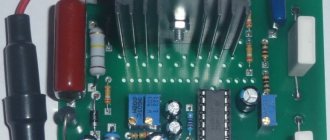
Printed circuit board for power regulator based on triac BTA12-600
Datasheet for BTA12-600
Feedback regulator circuit
Feedback is necessary to stabilize the speed of the electric motor, which can change under the influence of load. You can do this in two ways:
- Install a tachometer that measures the speed. This option allows for precise adjustment, but this increases the cost of implementing the solution.
- Monitor voltage changes on the electric motor and, depending on this, increase or decrease the “open” mode of the semiconductor switch.
The latter option is much easier to implement, but requires slight adjustment to the power of the electric machine used. Below is a diagram of such a device.
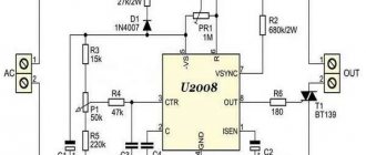
Power regulator with feedback
Designations:
- Resistors: R1 – 18 kOhm (2 W); R2 - 330 kOhm; R3 – 180 Ohm; R4 and R5 – 3.3 kOhm; R6 – must be selected as described below; R7 – 7.5 kOhm; R8 – 220 kOhm; R9 – 47 kOhm; R10 - 100 kOhm; R11 – 180 kOhm; R12 – 100 kOhm; R13 – 22 kOhm.
- Capacitors: C1 - 22 µF x 50 V; C2 - 15 nF; C3 – 4.7 µF x 50 V; C4 – 150 nF; C5 - 100 nF; C6 – 1 µF x 50 V..
- Diodes D1 – 1N4007; D2 – any 20 mA indicator LED.
- Triac T1 – BTA24-800.
- Microcircuit – U2010B.
This circuit ensures a smooth start of the electrical installation and protects it from overload. Three operating modes are allowed (set by switch S1):
- A – When overload occurs, LED D2 turns on, indicating overload, after which the engine reduces speed to minimum. To exit the mode, you must turn off and turn on the device.
- B - If there is an overload, LED D2 turns on, the motor is switched to work at minimum speed. To exit the mode, it is necessary to remove the load from the electric motor.
- C – Overload indication mode.
Setting up the circuit comes down to selecting resistance R6; it is calculated depending on the power of the electric motor using the following formula: . For example, if we need to control a 1500 W motor, then the calculation will be as follows: 0.25 / (1500 / 240) = 0.04 Ohm.
To make this resistance, it is best to use nichrome wire with a diameter of 0.80 or 1.0 mm. Below is a table that allows you to select the resistance R6 and R11, depending on the engine power.
Table for selecting resistance ratings depending on engine power
The above device can be used as a speed controller for motors of power tools, vacuum cleaners and other household equipment.
Power regulator on a triac: principle of operation, circuit options, how to do it yourself
To control some types of household appliances (for example, a power tool or a vacuum cleaner), a power regulator based on a triac is used. You can learn more about the operating principle of this semiconductor element from the materials posted on our website. In this publication we will consider a number of issues related to triac circuits for controlling load power. As always, let's start with theory.
The principle of operation of the regulator on a triac
Let us recall that a triac is usually called a modification of a thyristor that plays the role of a semiconductor switch with a nonlinear characteristic. Its main difference from the basic device is two-way conductivity when switching to the “open” operating mode, when current is supplied to the control electrode. Thanks to this property, triacs do not depend on voltage polarity, which allows them to be used effectively in circuits with alternating voltage.
In addition to the acquired feature, these devices have an important property of the base element - the ability to maintain conductivity when the control electrode is disconnected. In this case, the “closing” of the semiconductor switch occurs when there is no potential difference between the main terminals of the device. That is, when the alternating voltage crosses the zero point.
An additional bonus from this transition to the “closed” state is the reduction in the amount of interference during this phase of operation. Please note that a regulator that does not create interference can be created under the control of transistors.
Thanks to the properties listed above, it is possible to control the load power through phase control. That is, the triac opens every half-cycle and closes when crossing zero. The delay time for turning on the “open” mode, as it were, cuts off part of the half-cycle, as a result, the shape of the output signal will be sawtooth.
Signal shape at the output of the power regulator: A – 100%, B – 50%, C – 25%
In this case, the signal amplitude will remain the same, which is why it is incorrect to call such devices voltage regulators.
Regulator circuit options
Let's give a few examples of circuits that allow you to control load power using a triac, starting with the simplest.
Figure 2. Diagram of a simple triac power regulator powered by 220 V
Designations:
- Resistors: R1- 470 kOhm, R2 – 10 kOhm,
- Capacitor C1 – 0.1 µF x 400 V.
- Diodes: D1 – 1N4007, D2 – any indicator LED 2.10-2.40 V 20 mA.
- Dinistor DN1 – DB3.
- Triac DN2 - KU208G, you can install a more powerful analog BTA16 600.
With the help of dinistor DN1, the circuit D1-C1-DN1 is closed, which moves DN2 to the “open” position, in which it remains until the zero point (completion of the half-cycle). The moment of opening is determined by the time of accumulation on the capacitor of the threshold charge required to switch DN1 and DN2. The rate of charge C1 is controlled by the chain R1-R2, the total resistance of which determines the moment of “opening” of the triac. Accordingly, the load power is controlled through a variable resistor R1.
Despite the simplicity of the circuit, it is quite effective and can be used as a dimmer for filament lighting or a soldering iron power regulator.
Unfortunately, the above circuit does not have feedback, therefore, it is not suitable as a stabilized speed controller of a commutator electric motor.
Feedback regulator circuit
Feedback is necessary to stabilize the speed of the electric motor, which can change under the influence of load. You can do this in two ways:
- Install a tachometer that measures the speed. This option allows for precise adjustment, but this increases the cost of implementing the solution.
- Monitor voltage changes on the electric motor and, depending on this, increase or decrease the “open” mode of the semiconductor switch.
The latter option is much easier to implement, but requires slight adjustment to the power of the electric machine used. Below is a diagram of such a device.
Power regulator with feedback
Designations:
- Resistors: R1 – 18 kOhm (2 W); R2 – 330 kOhm; R3 – 180 Ohm; R4 and R5 – 3.3 kOhm; R6 – must be selected as described below; R7 – 7.5 kOhm; R8 – 220 kOhm; R9 – 47 kOhm; R10 – 100 kOhm; R11 – 180 kOhm; R12 – 100 kOhm; R13 – 22 kOhm.
- Capacitors: C1 – 22 µF x 50 V; C2 – 15 nF; C3 – 4.7 µF x 50 V; C4 – 150 nF; C5 – 100 nF; C6 – 1 µF x 50 V..
- Diodes D1 – 1N4007; D2 – any 20 mA indicator LED.
- Triac T1 – BTA24-800.
- Microcircuit – U2010B.
This circuit ensures a smooth start of the electrical installation and protects it from overload. Three operating modes are allowed (set by switch S1):
- A – When overload occurs, LED D2 turns on, indicating overload, after which the engine reduces speed to minimum. To exit the mode, you must turn off and turn on the device.
- B – If there is an overload, LED D2 turns on, the motor is switched to work at minimum speed. To exit the mode, it is necessary to remove the load from the electric motor.
- C – Overload indication mode.
Setting up the circuit comes down to selecting resistance R6; it is calculated depending on the power of the electric motor using the following formula: . For example, if we need to control a 1500 W motor, then the calculation will be as follows: 0.25 / (1500 / 240) = 0.04 Ohm.
To make this resistance, it is best to use nichrome wire with a diameter of 0.80 or 1.0 mm. Below is a table that allows you to select the resistance R6 and R11, depending on the engine power.
Table for selecting resistance ratings depending on engine power
The above device can be used as a speed controller for motors of power tools, vacuum cleaners and other household equipment.
Regulator for inductive load
Those who try to control an inductive load (for example, a welding machine transformer) using the above circuits will be disappointed. The devices will not work, and the triacs may fail. This is due to a phase shift, which is why during a short pulse the semiconductor switch does not have time to switch to the “open” mode.
There are two options to solve the problem:
- Supplying a series of similar pulses to the control electrode.
- Apply a constant signal to the control electrode until it passes through zero.
The first option is the most optimal. Here is a diagram where this solution is used.
Power regulator circuit for inductive load
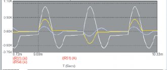
As can be seen from the following figure, which shows oscillograms of the main signals of the power regulator, a packet of pulses is used to open the triac.
Oscillograms of the input (A), control (B) and output signal (C) of the power regulator
This device makes it possible to use regulators on semiconductor switches to control an induction load.
A simple power regulator on a triac with your own hands
At the end of the article, we will give an example of a simple power regulator. In principle, you can assemble any of the above circuits (the most simplified version was shown in Figure 2). For this device it is not even necessary to make a printed circuit board; the device can be assembled by surface mounting. An example of such an implementation is shown in the figure below.
Homemade power regulator
This regulator can be used as a dimmer, and can also be used to control powerful electric heating devices. We recommend choosing a circuit in which a semiconductor switch with characteristics corresponding to the load current is used for control.
Regulator for inductive load
Those who try to control an inductive load (for example, a welding machine transformer) using the above circuits will be disappointed. The devices will not work, and the triacs may fail. This is due to a phase shift, which is why during a short pulse the semiconductor switch does not have time to switch to the “open” mode.
There are two options to solve the problem:
- Supplying a series of similar pulses to the control electrode.
- Apply a constant signal to the control electrode until it passes through zero.
The first option is the most optimal. Here is a diagram where this solution is used.
Power regulator circuit for inductive load
As can be seen from the following figure, which shows oscillograms of the main signals of the power regulator, a packet of pulses is used to open the triac.
Oscillograms of the input (A), control (B) and output signal (C) of the power regulator
This device makes it possible to use regulators on semiconductor switches to control an induction load.
A simple power regulator on a triac with your own hands
At the end of the article, we will give an example of a simple power regulator. In principle, you can assemble any of the above circuits (the most simplified version was shown in Figure 2). For this device it is not even necessary to make a printed circuit board; the device can be assembled by surface mounting. An example of such an implementation is shown in the figure below.
Homemade power regulator
This regulator can be used as a dimmer, and can also be used to control powerful electric heating devices. We recommend choosing a circuit in which a semiconductor switch with characteristics corresponding to the load current is used for control.
Can the vacuum cleaner's power regulator be used to charge batteries?
Disassembled the vacuum cleaner for cleaning. It has such a power regulator. Is it possible to remove it so that the motor can work at full power, because... the regulator at a lower speed; I don’t use a vacuum cleaner; it’s weak. How to connect the motor directly? And is it possible to use this regulator in a circuit for charging a car battery?
Comments 72
I have a good circuit, as simple as 3 kopecks. Trans, diode bridge, thyristor, transistor KT117, and wiring. Well, and an ammeter. If anyone needs it, I can send you the circuit.
What is it good for?, what does it give? Does it regulate voltage and current? Should the payment be sent?((
It regulates the current, the voltage at the output of the transformer should be 17 volts, naturally the diodes have a current within 8A, the thyristor is the most important component (if it is short it crashes, there is no protection circuit).
wladgorinov
I have a good circuit, as simple as 3 kopecks. Trans, diode bridge, thyristor, transistor KT117, and wiring. Well, and an ammeter. If anyone needs it, I can send you the circuit.
please send me a PM
Why bother suffering, the half-bridge circuit is 4.5 Amperes. It will take longer to charge, but it will be enough for recharging.
You can leave the vacuum cleaner without a regulator, it will thresh at maximum.
Can. if this regulator is connected from the mains side to a “brainless” charger on an iron transformer
Have you tried it yourself?
But you need to understand: it will allow you to regulate the current, but this will not make the charger automatic. Those. You still have to monitor the voltage/current
I also lick it when I charge it, because... no smart charging(
short-circuit
Can. if this regulator is connected from the mains side to a “brainless” charger on an iron transformer
This is the only one I have) An ampere-voltmeter arrived from China, I want to plug it in. Those. your answer is yes?! Will it regulate the current?
I made a basic charge for the battery by taking an 18-volt laptop charger and connecting it in series with a regular 12-volt lamp. 8 hours and the battery is charged))))
Yes, I did that, it works!)
buy a standard charger, because cutting it out leads to getting caught. I often saw discarded old TVs in landfills; you can also assemble a charger and a welding machine from them. There are diagrams on the Internet
I read the advice and laughed. Some comments are so ridiculous
And what’s interesting is that crazy ideas are getting a ton of comments
Google the offices in your city that sell spare parts for household appliances, and buy a normal motor for a vacuum cleaner there. It’s better to leave the idea with a dimmer for charging the battery