Often, when operating various equipment, it becomes necessary to control the speed of rotation of a DC electric motor. For this, special regulators or frequency converters are used. The simplest regulator can be made with your own hands.
During the operation of modern power tools and various equipment, it often becomes necessary to control the power and rotation speed of DC motors. To solve such problems, it is customary to use special regulators or frequency converters, which are now presented in a large variety on the electrical market. A correctly selected frequency converter allows you to smoothly reduce or increase the shaft speed and ensure long-term uninterrupted operation of the mechanisms.
To better understand the principle of operation of a DC motor speed controller, it is recommended to make it yourself. Even a person without deep knowledge and specialized skills in radio electronics can do this. To create a homemade device, you will definitely need a 12V or 24V regulator circuit that is optimally suited to the features and characteristics of your electric motor, operating from a regular 220-volt home power supply or intended for a three-phase network.
Areas of application and selection criteria for speed controller
Often, a rotation controller for electric motors is necessary for correct operation:
- industrial and household electric drives;
- electric welding machines;
- heating and air conditioning systems;
- electric furnaces;
- power supplies for computer equipment;
- voltage stabilizers;
- washing and sewing machines;
- vacuum cleaners and much more.
When choosing a DC motor speed controller, you need to pay attention to the features of the device and its recommended use:
- in commutator-type electric motors, vector regulators are more often used, but scalar ones are considered more reliable;
- the declared power of the controller must correspond to the rated characteristics of the power unit (even slightly exceed them to ensure more stable and safe operation of the system);
- voltage characteristics are selected within the permissible range;
- The rotation speed conversion parameters must meet the technical requirements of the equipment.
It is also important to take into account the overall dimensions, number of inputs/outputs, warranty period, etc.
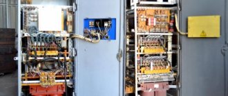
Generalized controller circuit
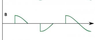
An example of a controller that implements the principle of controlling a motor without power loss is a thyristor converter. These are proportional-integral circuits with feedback, which provide strict control of characteristics, ranging from acceleration-braking to reverse. The most effective is pulse-phase control: the repetition rate of the unlocking pulses is synchronized with the network frequency. This allows you to maintain torque without increasing losses in the reactive component. The generalized diagram can be represented in several blocks:
- power controlled rectifier;
- rectifier control unit or pulse-phase control circuit;
- tachogenerator feedback;
- current control unit in the motor windings.
Before delving into a more precise device and principle of regulation, it is necessary to decide on the type of commutator motor. The control scheme for its performance characteristics will depend on this.
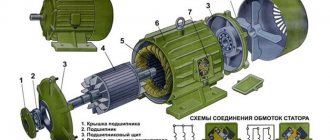
Design features and operating principle of the frequency converter
Electronic frequency converters are used to control the operation of electric motors in both a three-phase 380V and single-phase 220V power supply. Their work is based on changing the amplitude and frequency of the electrical signal, which allows you to smoothly change the parameters of the rotor speed of the power unit. The design of most such devices, as a rule, is based on semiconductor-type transistors with pulse-width modulators. Speed adjustment is carried out using a control unit installed on the microcontroller.
Frequently used in power tools and household appliances, commutator-type DC motors are distinguished by the fact that when directly connected to a 220-volt power supply, they begin to produce maximum speed. This increases the load on the drive and contributes to its rapid wear. In addition, at high rotor speeds, a lot of heat is generated, which leads to overheating of the working mechanisms, melting of windings and cables, and can also cause a short circuit. Therefore, it is highly recommended to install a power and frequency regulator here, even if control over the speed in the technical process and operation of the electrical installation is not provided.
Features of speed control
It is important to know that each motor, when rotating, consumes not only active, but also reactive power. In this case, the level of reactive power will be higher, which is due to the nature of the load. In this case, the task of designing devices for regulating the rotation speed of commutator motors is to reduce the difference between active and reactive powers. Therefore, such converters will be quite complex, and it is not easy to make them yourself.
You can construct only some semblance of a regulator with your own hands, but there is no point in talking about saving power. What is power? In electrical terms, it is the current drawn multiplied by the voltage. The result will give a certain value that includes active and reactive components. To isolate only the active one, that is, to reduce losses to zero, it is necessary to change the nature of the load to active. Only semiconductor resistors have these characteristics.
Using a homemade regulator
Previously, the most common type of engine governor was a mechanical one, which used a gear drive and a variator. But due to wear and tear of mechanical parts and the influence of external factors, they often failed and required repair. Electronic devices that allow you to increase the voltage smoothly or stepwise have proven themselves much better. In addition, they are distinguished by their compact size and the ability to more accurately adjust the operating parameters of the electrical installation.
Making a simple 12B DC motor controller with your own hands is not difficult, even if you have basic skills. To do this, it is enough to have the following components:
- switch for several positions;
- set of wirewound resistors;
- relay and control blocks.
With the help of resistors, the voltage from the power source changes, and therefore the speed of the electric motor. Such a homemade engine regulator accelerates it stepwise by setting the switch to the appropriate position. It can be effectively used to start asynchronous and contact type power units.
This device operates according to the following principle:
- voltage from the power source is applied to the capacitor, which is fully charged;
- the current is redirected to the outgoing wire and resistor;
- the thyristor electrode connected to the positive capacitor contact receives the load;
- after the voltage charge is transferred, the second semiconductor opens;
- the load coming from the capacitor is passed through the thyristor and the capacitor is discharged;
- the half-cycle cycle repeats.
If the regulator circuit additionally contains a triac or a device with a similar operating principle, then the change in voltage power proceeds smoothly. This means that the electric motor will pick up speed without jerking or noticeable vibrations, gradually reaching the required operating power. Also, to ensure better regulation, variable resistors can be included in the circuit.
Regulating the rotation speed of the NV DPT introducing additional resistance into the armature circuit
Additional resistance (rheostat rd) is included in the armature circuit in the same way as a starting rheostat (PR). However, unlike the latter, it must be designed for continuous current flow.
When resistance rd is included in the armature circuit, the frequency expression (29.5) takes the form
, (29.12)
where is the rotation speed in idle mode;
- change in rotation speed caused by a voltage drop in the armature circuit.
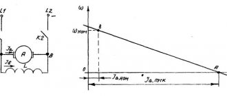
With increasing rd increases, which leads to a decrease in rotation speed. The dependence n = f(rd) is also illustrated by the mechanical characteristics of an independent excitation motor (Fig. 29.4, a
)
:
with increasing rd, the slope of the mechanical characteristics increases, and the rotation speed at a given load on the shaft (M = Mnom) decreases. This method provides smooth control of the rotation speed over a wide range (only towards a decrease in frequency from the nominal one), however, it is uneconomical due to significant losses of electricity in the control rheostat (I2a *rD), which increase rapidly with increasing engine power.
Rice. 29.4. Mechanical characteristics of parallel excitation motor:
A
- when introducing additional resistance into the armature circuit;
b
— when the main magnetic flux changes;
c - when the voltage in the armature circuit changes
Speed controller on a PWM transistor
The process of adjusting the speed of a low-power electric motor can be organized using a PWM transistor and series-connected resistors from a power source. This method is quite easy to implement on your own, but it has a low efficiency and does not allow you to smoothly increase or decrease the rotor speed.
A homemade PWM speed controller using transistors has the following features:
- modern pulse-width modulation transistors contain a 150-Hz sawtooth voltage generator;
- operational amplifiers are used as a comparator;
- The duration of the pulses is controlled by a variable resistor, as a result of which the speed is adjusted.
The amplitude of the transistor pulses corresponds to the voltage amplitude of the power source. It is smooth and constant. Thanks to this property, adjustment of the electric motor speed is possible even when a minimum voltage is supplied to the transformer winding. Such a PWM speed controller allows you to connect a microcontroller to the transistor and thus automate the setup and adjustment of the operation of the electric drive. You can also include other components in the circuit that expand the functionality and automation capabilities of the electrical installation.
Parts of electric motor rotation controllers
In these circuits, it is possible to use the following replacements of radio components: transistor KT817B - KT815, KT805; KT117A can be replaced with KT117B-G or 2N2646; Operational amplifier K140UD7 on K140UD6, KR544UD1, TL071, TL081; timer NE555 - S555, KR1006VI1; microcircuit TL074 - TL064, TL084, LM324.
When using a more powerful load, the KT817 key transistor can be replaced with a powerful field-effect transistor, for example, IRF3905 or similar.
Based on the powerful triac BT138-600, you can assemble a circuit for an AC motor speed controller. This circuit is designed to regulate the rotation speed of electric motors of drilling machines, fans, vacuum cleaners, grinders, etc. The motor speed can be adjusted by changing the resistance of potentiometer P1. Parameter P1 determines the phase of the trigger pulse, which opens the triac. The circuit also performs a stabilization function, which maintains engine speed even under heavy load.
For example, when the motor of a drilling machine slows down due to increased metal resistance, the EMF of the motor also decreases. This leads to an increase in voltage in R2-P1 and C3 causing the triac to open for a longer time, and the speed increases accordingly.
Thyristor control of electric motor speed
The thyristor regulator also allows you to change the speed of the power unit shaft. It is also called a dimmer or phase regulator. With this connection method, the electric motor is connected either to a break in the network cable, or behind a rectifier bridge that powers the anode thyristor circuit. This method of controlling the motor speed is considered quite reliable, provided that there are no violations of the integrity or order of contact connections in the load circuit. If you connect a commutator electric motor through a thyristor regulator, the brushes may begin to spark, since the load current will pulse.
Although, to control 12-volt DC motors of the collector type, you can adapt a thyristor regulator, which will have some features:
- the electric motor and power thyristor are connected to one of the diagonals of the rectifier bridge, and the voltage from the mains is supplied to the other diagonal;
- Thyristors are controlled not with short pulse signals, but with a wider range, which makes it possible to eliminate the detrimental effect on the operation of the regulator of short-term load drops characteristic of commutator electric motors.
The generator of short, up to several milliseconds, positive pulses is assembled on a unijunction transistor VT1. It is designed to operate the auxiliary thyristor VS1. The trapezoidal supply voltage is supplied to the generator by limiting the 100-Hz positive half-waves of the sinusoidal voltage by the zener diode VD1. Each such half-wave gradually charges capacitor C1 through the resistive chain R1-R3.
When the voltage required to open the transistor appears on the capacitor, a positive pulse is applied from resistor R5 to the electrode of the control trinistor VS1, as a result of which this trinistor opens, and the power trinistor VS2 receives a pulse signal that is longer than the control signal and Electric motor M1 receives power.
The rotation speed of the electric motor rotor is adjusted using a variable resistor R1, which is responsible for the opening moment of the power and control thyristors, and therefore for the load power. The anode of the VS2 thyristor in its circuit has an inductive load, so spontaneous opening is possible even without receiving a control signal. To prevent this from happening, a diode VD is mounted, connected in parallel with the excitation winding LB.
Design Features
The microcircuit is equipped with everything necessary for high-quality engine control in various speed modes, from braking to acceleration and rotation at maximum speed. Therefore, its use greatly simplifies the design, while simultaneously making the entire drive universal , since you can select any speed with a constant torque on the shaft and use it not only as a drive for a conveyor belt or drilling machine, but also for moving a table.
The characteristics of the microcircuit can be found on the official website. We will indicate the main features that will be required to construct the converter. These include: an integrated frequency-to-voltage conversion circuit, an acceleration generator, a soft starter, a Tacho signal processing unit, a current limiting module, etc. As you can see, the circuit is equipped with a number of protections that will ensure stable operation of the regulator in different modes.
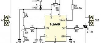
The figure below shows a typical circuit diagram for connecting a microcircuit.
The scheme is simple, so it is quite reproducible with your own hands. There are some features that include limit values and speed control method:
- The maximum current in the motor windings should not exceed 10 A (subject to the configuration shown in the diagram). If you use a triac with a large forward current, the power can be higher. Please note that you will need to change the resistance in the feedback circuit downward, as well as the inductance of the shunt.
- The maximum rotation speed is 3200 rpm. This characteristic depends on the type of engine. The circuit can control motors up to 16 thousand rpm.
- Acceleration time to maximum speed reaches 1 second.
- Normal acceleration is achieved in 10 seconds from 800 to 1300 rpm.
- The engine uses an 8-pole tachogenerator with a maximum output voltage of 30 V at 6000 rpm. That is, it should produce 8 mV per 1 rpm. At 15,000 rpm it should show 12 V.
- To control the motor, a 15A triac with a maximum voltage of 600 V is used.
If you need to organize a motor reverse, then for this you will have to supplement the circuit with a starter that will switch the direction of the excitation winding. You will also need a zero speed control circuit to give permission for reverse. Not shown in the picture.
Introduction of automation
The presence of modern microcontroller control in speed controllers and frequency converters makes it possible to improve the operating parameters of the drive, and the motor itself can operate in a fully automatic mode, when the controller used smoothly or stepwise changes the rotation speed of the rotor of the power unit. Today, microcontroller control uses processors that have different numbers of outputs and inputs. You can connect various kinds of electronic keys and buttons, various signal loss sensors, etc. to such a microcontroller.
The modern electrical market offers a wide range of converters and frequency controllers for any type of electric motor. But if you have even minimal skills in working with radio components and the ability to read electrical circuits, you can assemble a device with your own hands that will gradually or stepwise change the engine speed. Additionally, you can include a control triac rheostat and a resistor in the circuit, which will make it possible to smoothly change the speed, and the presence of microcontroller control completely automates the operation of the electric drive.
Scheme selection
Having found out all the conditions under which the motor will be used, you can begin to manufacture a speed controller for the commutator motor. You should start by choosing a suitable scheme that will provide you with all the necessary characteristics and capabilities. You should remember them:
- Speed regulation from 0 to maximum.
- Providing good torque at low speeds.
- Smooth speed control.
Looking at many schemes on the Internet, we can conclude that few people are creating such “units”. This is due to the complexity of the control principle, since it is necessary to organize the regulation of many parameters. Thyristor opening angle, control pulse duration, acceleration-deceleration time, torque rise rate. These functions are handled by a circuit on the controller that performs complex integral calculations and transformations. Let's consider one of the schemes, which is popular among self-taught craftsmen or those who simply want to put to good use an old motor from a washing machine.
How to make it yourself?
There are various options for adjustment schemes. Let us present one of them in more detail.
Here is how it works:
Initially, this device was developed to adjust the commutator motor in electric vehicles. We were talking about one where the supply voltage is 24 V, but this design is also applicable to other engines.
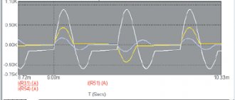
The weak point of the circuit, which was identified during testing of its operation, is its poor suitability at very high current values. This is due to some slowdown in the operation of the transistor elements of the circuit.
It is recommended that the current be no more than 70 A. There is no current or temperature protection in this circuit, so it is recommended to build in an ammeter and monitor the current visually. The switching frequency will be 5 kHz, it is determined by capacitor C2 with a capacity of 20 nf.
As the current changes, this frequency can change between 3 kHz and 5 kHz. Variable resistor R2 is used to regulate the current. When using an electric motor at home, it is recommended to use a standard type regulator.
At the same time, it is recommended to select the value of R1 in such a way as to correctly configure the operation of the regulator. From the output of the microcircuit, the control pulse goes to a push-pull amplifier using transistors KT815 and KT816, and then goes to the transistors.
The printed circuit board has a size of 50 by 50 mm and is made of single-sided fiberglass:
This diagram additionally shows 2 45 ohm resistors. This is done for the possible connection of a regular computer fan to cool the device. When using an electric motor as a load, it is necessary to block the circuit with a blocking (damper) diode, which in its characteristics corresponds to twice the load current and twice the supply voltage.
Operating the device in the absence of such a diode may lead to failure due to possible overheating.
In this case, the diode will need to be placed on the heat sink. To do this, you can use a metal plate that has an area of 30 cm2.
Regulating switches work in such a way that the power losses on them are quite small. IN
In the original design, a standard computer fan was used. To connect it, a limiting resistance of 100 Ohms and a supply voltage of 24 V were used.
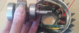
The assembled device looks like this:
When manufacturing a power unit (in the lower figure), the wires must be connected in such a way that there is a minimum of bending of those conductors through which large currents pass. We see that the manufacture of such a device requires certain professional knowledge and skills. Perhaps in some cases it makes sense to use a purchased device.