General information, device, scope of application
One of the reasons for the interest in BD is the increased need for high-speed micromotors with precise positioning. The internal structure of such drives is shown in Figure 2.
Rice. 2. Brushless motor design
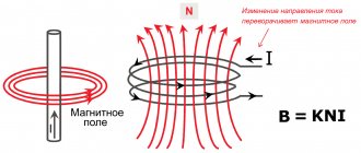
As you can see, the design consists of a rotor (armature) and a stator, the first has a permanent magnet (or several magnets arranged in a certain order), and the second is equipped with coils (B) to create a magnetic field.
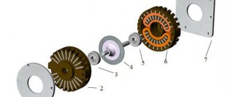
It is noteworthy that these electromagnetic mechanisms can be either with an internal armature (this type of design can be seen in Figure 2) or external (see Figure 3).
Rice. 3. Outrunner design
Accordingly, each of the designs has a specific scope of application. Devices with an internal armature have a high rotation speed, so they are used in cooling systems, as power plants for drones, etc. External rotor actuators are used where precise positioning and torque resistance are required (robotics, medical equipment, CNC machines, etc.).
Brushless motor in a computer disk drive
Engine design options
The motor winding can have different designs. The winding of the classical design is wound on a steel core. Another winding design option is a winding without a steel core. The conductors of this winding are evenly distributed along the circumference of the stator. The characteristics of the winding are different, which is reflected in the characteristics of the motor. In addition, the windings can be made for a different number of phases and with a different number of pole pairs.
Brushless motors can also have designs that differ in the relative position of the rotor and stator. The most common design is when the rotor is covered by the stator from the outside - motors with an internal rotor. But it is also possible, and found in practice, to have a design in which the rotor is located outside the stator - motors with an external rotor. The third option is that the stator is located parallel to the rotor and both are located perpendicular to the axis of rotation of the engine. Such motors are called motors of axial design.
The position sensor, which measures the angular position of the motor rotor, is an important part of the drive system built on a brushless motor. This sensor can be very different both in type and principle of operation. The type of sensors traditionally used for this purpose are Hall sensors with logical output, installed on each motor phase. The output signals of these sensors make it possible to determine the position of the rotor with an accuracy of up to 60° - sufficient to implement the simplest methods of controlling the windings. To implement motor control methods that involve the formation of a sinusoidal voltage system on the motor windings using PWM, a more accurate sensor, for example, an encoder, is required. Incremental encoders, very widely used in modern electric drives, can only provide sufficient information about the rotor position when used in conjunction with Hall sensors. If the brushless motor is equipped with an absolute position sensor - an absolute encoder or resolver (ASKVT), then Hall sensors are no longer needed, since any of these sensors provides complete information about the position of the rotor.
You can control a brushless motor without using a rotor position sensor - sensorless commutation. In this case, information about the rotor position is restored based on the readings of other sensors, for example, motor phase current sensors or voltage sensors. This control method often entails a number of disadvantages (limited speed range, high sensitivity to engine parameters, special start procedure), which limits its spread.
Principle of operation
Unlike other drives, for example, an AC asynchronous machine, the BD requires a special controller to operate, which turns on the windings in such a way that the vectors of the magnetic fields of the armature and stator are orthogonal to each other. That is, in essence, the driver device regulates the torque acting on the DB armature. This process is clearly demonstrated in Figure 4.
Phases of operation of a brushless drive
As you can see, for each movement of the armature it is necessary to perform a certain commutation in the stator winding of a brushless type motor. This principle of operation does not allow smooth control of rotation, but makes it possible to quickly gain momentum.
Controller settings
To enter the settings of the regulators, we need a special program BLHeliSuite32. Download it, install it and launch it. The brain of the quadcopter itself acts as an adapter. After all the manipulations, we connect the brain to the computer and connect the battery to the quadcopter. In the window, select the com port we need and click connect. To read the settings of the regulators, click Read setup.
A window pops up about the firmware versions of each controller and that everything is in order with them.
We press ok and we are informed that the settings of 1 controller have been read, we press ok and we can start configuring if necessary.
Among the interesting things, I would highlight the thermal protection of each regulator and current protection, that is, the regulator will not consume more than the specified ampere value.
Differences between brushed and brushless motors
The collector-type drive differs from the BD both in design features (see Fig. 5.) and in the principle of operation.
Rice. 5. A – brushed motor, B – brushless
Let's look at the design differences. From Figure 5 it can be seen that the rotor (1 in Fig. 5) of a commutator type motor, unlike a brushless one, has coils with a simple winding circuit, and permanent magnets (usually two) are installed on the stator (2 in Fig. 5 ). In addition, a commutator is installed on the shaft, to which brushes are connected, supplying voltage to the armature windings.
Let's briefly talk about the operating principle of collector machines. When voltage is applied to one of the coils, it is excited and a magnetic field is formed. It interacts with permanent magnets, this causes the armature and the collector placed on it to rotate. As a result, power is supplied to the other winding and the cycle repeats.
The rotation frequency of an armature of this design directly depends on the intensity of the magnetic field, which, in turn, is directly proportional to the voltage. That is, to increase or decrease the speed, it is enough to increase or decrease the power level. And to reverse it is necessary to switch the polarity. This control method does not require a special controller, since the speed controller can be made based on a variable resistor, and a regular switch will work as an inverter.
We discussed the design features of brushless motors in the previous section. As you remember, connecting them requires a special controller, without which they simply will not work. For the same reason, these engines cannot be used as a generator.
It is also worth noting that in some drives of this type, for more efficient control, the rotor positions are monitored using Hall sensors. This significantly improves the characteristics of brushless motors, but increases the cost of an already expensive design.
Let's start inspecting the parcel and contents.
The regulator arrives in a simple bubble mailer envelope. Inside there is a regulator in an antistatic bag, a bag with 4 PCB spacers and instructions with pinouts.
Let's first inspect the bottom side of the board. As you can see, the soldering is good, each regulator has its own individual current sensor (from which we can receive data). Also striking is a large number of capacitors; according to the manufacturer, there are enough of them soldered, so installing additional. no capacitors needed.
A strange and controversial decision regarding the exposed areas of the board. It is not clear why this was done, but let’s leave it out.
We see 4 32-bit STM processors on the board. Marking - f051k86
Then there are 4 key drivers. Marking – fortior fd6288q
Let's turn the board over and inspect its other side. As you can see, all the mosfets are collected in one place. My opinion is that this is only better since at least the tracks need to be routed along the board, it looks more aesthetically pleasing, there is more space directly for outputting the tracks to which the motor wires will be soldered. Mosfets marking - QN3109 721 03Q
Now let's look at the tracks!
As you can see, they have become larger. It is also clear that the path does not end with the bare part, there is a supply of more on the sides! Looks impressive.
If you look at a cross-section of the board, there is a feeling that the tracks are approximately recessed to the floor of the board. Unfortunately, the camera could not show this clearly, and I could be wrong. But this controller flies and there are no problems with the tracks, more on that later.
The capacitors located on the edge of the board cause a little concern. But I screwed a plastic nut onto the bolt and everything fit perfectly with a reserve.
Installation photo
I tried to make it as clear as possible
Let's take a look at the instructions. What I would like to pay attention to is that the operating voltage in the instructions is 3-4s and on the website it is 3-6s! Personally, I've only flown 4s.
What I was very happy about was that they added a telemetry output to the connector!!! Now everything is connected with one “cable” and there is no additional soldering. But! If you need Airbot left dimes (SWC) on the board with telemetry output
General plan of pinout and numbering of parts on the board.
How to start a brushless motor?
To make drives of this type work, you will need a special controller (see Fig. 6). Without it, launching is impossible.
Rice. 6. Brushless motor controllers for modeling
There is no point in assembling such a device yourself; it will be cheaper and more reliable to purchase a ready-made one. You can select it based on the following characteristics characteristic of PWM channel drivers:
- The maximum permissible current strength, this characteristic is given for the normal operation of the device. Quite often, manufacturers indicate this parameter in the model name (for example, Phoenix-18). In some cases, a value is given for a peak mode that the controller can maintain for several seconds.
- Maximum nominal voltage for continuous operation.
- Resistance of the internal circuits of the controller.
- The permissible speed is indicated in rpm. Beyond this value, the controller will not allow increasing rotation (the limitation is implemented at the software level). Please note that the speed is always given for two-pole drives. If there are more pole pairs, divide the value by their number. For example, the number 60000 rpm is indicated, therefore, for a 6-magnetic motor the rotation speed will be 60000/3=20000 prm.
- The frequency of the generated pulses, for most controllers this parameter ranges from 7 to 8 kHz; more expensive models allow you to reprogram the parameter, increasing it to 16 or 32 kHz.
Please note that the first three characteristics determine the power of the database.
Connection diagram
As mentioned above, a brushless motor requires a special controller to operate. On Aliexpress you can find both sets of motor and controller, and separately. The controller is also called ESC Motor or Electric Speed Controller. They are selected according to the current supplied to the load.
Usually, connecting an electric motor to a controller is straightforward and understandable even for dummies. The main thing you need to know is that to change the direction of rotation you need to change the connection of any two phases, in fact, the same as in three-phase asynchronous or synchronous electric motors.
There are a number of technical solutions and schemes online, both complex and for dummies, which you can see below.
In this video, the author explains how to connect a BC motor with an Arduino.
And in this video you will learn about different ways to connect to different regulators and how you can do it yourself. The author demonstrates this using the example of a motor from an HDD, and a couple of powerful specimens - an inrunner and an outrunner.
By the way, we also attach the diagram from the video for repetition:
Three-phase brushless DC motor
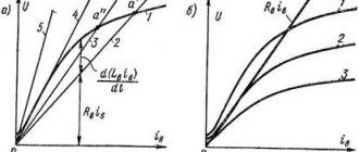
Most databases are implemented in three-phase design. To control such a drive, the controller has a DC-to-three-phase pulse converter (see Fig. 7).
Figure 7. OBD voltage diagrams
To explain how such a valve motor works, together with Figure 7, you should consider Figure 4, which shows in turn all the stages of the drive’s operation. Let's write them down:
- A positive impulse is applied to coils “A”, while a negative impulse is applied to “B”, as a result the armature moves. Sensors will record its movement and send a signal for the next switching.
- Coil “A” is turned off, and a positive pulse goes to “C” (“B” remains unchanged), then a signal is sent to the next set of pulses.
- “C” is positive, “A” is negative.
- A pair of “B” and “A” works, which receive positive and negative impulses.
- A positive pulse is re-applied to “B”, and a negative pulse to “C”.
- Coils “A” are turned on (+ is supplied) and the negative pulse on “C” is repeated. Then the cycle repeats.
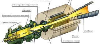
In the apparent simplicity of control there are a lot of difficulties. It is necessary not only to monitor the position of the armature in order to produce the next series of pulses, but also to control the rotation speed by adjusting the current in the coils. In addition, you should select the most optimal parameters for acceleration and braking. It is also worth remembering that the controller must be equipped with a unit that allows you to control its operation. The appearance of such a multifunctional device can be seen in Figure 8.
Rice. 8. Multi-function brushless motor control controller
Motor control circuit via Arduino
To remove the motor from the HDD case, simply unscrew all the screws. Some screws may be hidden under the label.
Attention! There is a ribbon connected to the drive, do not pull it because there are very thin wires inside that are connected to the motor coils. We suggest soldering additional wires, as seen in the photo.
Then solder the extension wires. We connect to Arduino according to the following scheme:
You need 3 digital contacts to send a signal, here contacts 2, 3, 4.
Advantages and disadvantages
The electric brushless motor has many advantages, namely:
- The service life is significantly longer than that of conventional collector analogues.
- High efficiency.
- Quickly set maximum rotation speed.
- It is more powerful than CD.
- The absence of sparks during operation allows the drive to be used in fire hazardous conditions.
- No additional cooling required.
- Easy to use.
Now let's look at the cons. A significant drawback that limits the use of databases is their relatively high cost (including the price of the driver). Among the inconveniences is the inability to use the database without a driver, even for short-term activation, for example, to check its functionality. Problematic repairs, especially if rewinding is required.
Scope of application of BLDC
BDTPs are widely used for small household appliances, audio, video devices, as well as PC and laptop components, such as hard drives, players, drives, batteries and batteries.
They are also used for gadgets and devices for entertainment and work, such as radio-controlled devices. Industrial machines and professional factory equipment cannot do without BDTP.
Brushless motors are required to equip the wheels of modern electrical equipment, such as scooters, motorcycles, bicycles and Segways. Eco-friendly new cars are no exception.
As you can see, the area of the BDTP is incredibly huge, since the absence of the collector itself allows the device to be used in places with an increased risk of emergency situations, too high humidity, and sudden temperature changes.
It has come to the point that BDTPs are used in space production, which cannot but please observers of technological progress.