Self-excitation of a parallel excitation generator
Self-excitation of the parallel excitation generator occurs when the following conditions are met: 1) the presence of residual magnetic flux of the poles; 2) correct connection of the ends of the field winding or the correct direction of rotation. In addition, the resistance of the excitation circuit Rв at a given rotation speed n must be below a certain critical value, or the rotation speed at a given Rв must be higher than a certain critical value.
For self-excitation, it is enough that the residual flow is 2 - 3% of the nominal one. A residual flow of this value is almost always present in a machine that has already been running. A newly manufactured machine or a machine that has become demagnetized for some reason must be magnetized by passing current from an external source through the field winding.
If the necessary conditions are met, the self-excitation process proceeds as follows. A small electromotive force (emf), induced in the armature by the residual magnetic flux, causes a small current iв in the field winding. This current causes an increase in the flux of poles, and therefore an increase in e. d.s., which causes a further increase in iв, and so on. This avalanche-like self-excitation process continues until the generator voltage reaches a steady value.
If the connection of the ends of the field winding or the direction of rotation is incorrect, then a current i in the opposite direction occurs, causing a weakening of the residual flux and a decrease in e. d.s., as a result of which self-excitation is impossible. Then it is necessary to switch the ends of the field winding or change the direction of rotation. You can verify that these conditions are met by monitoring the armature voltage with a voltmeter with a small measurement limit when closing and opening the excitation circuit.
The polarity of the generator terminals during self-excitation is determined by the polarity of the residual flow. If, for a given direction of rotation, the polarity of the generator needs to be changed, then the machine should be remagnetized by supplying current to the field winding from an external source.
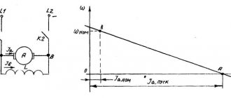
Figure 1. Self-excitation of a parallel excitation generator at different excitation circuit resistances (a) and at different rotation speeds (b)
Let's take a closer look at the process of self-excitation at idle. In Figure 1, a, curve 1 represents the idle speed characteristic (x. x. x.), and straight line 2 is the so-called excitation circuit characteristic or the dependence Uв = Rв × iв, where Rв = const is the resistance of the excitation circuit, including the resistance of the adjusting rheostat.
During the process of self-excitation iв ≠ const and the voltage at the ends of the excitation circuit
where Lв is the inductance of the excitation circuit.
Armature voltage at no-load (I = 0)
Uа = Eа – iв × Rа
is depicted in Figure 1, and curve 1. Since the current iв is small, then practically Ua = Ea.
But in a parallel excitation generator (see Figure 1, b, in the article “General information about direct current generators”) Uа = Uв. Therefore, the difference between the ordinates of curve 1 and straight line 2 in Figure 1, a is d(Lвiв)/dt and characterizes the speed and direction of change of iв. If line 2 passes below curve 1, then
iв grows and the machine self-excites to the voltage corresponding in Figure 1, and the point of intersection of curve 1 and straight line 2, at which
and the growth of iв therefore stops.
From an examination of Figure 1, a, it follows that the increase in iв and, therefore, Ua occurs slowly at first, then accelerates and slows down again towards the end of the process. The self-excitation process that has begun stops or is limited at point a' due to the curvilinearity of x. X. X. In the absence of saturation, Ua would theoretically increase to Ua = ∞.
In general, any self-excitation processes - electrical, and others, observed in various devices - are limited only by the nonlinearity of the system characteristics.
| Figure 2. Magnetic saturation bridges in a magnetic circuit |
If Rв is increased, then instead of straight line 2 we get straight line 3 (Figure 1, a). In this case, the self-excitation process slows down and the machine voltage, determined by point a'', will be less. With a further increase in Rv, we obtain straight line 4, tangent to curve 1. In this case, the machine will be on the verge of self-excitation: with small changes in n or Rv (for example, due to heating), the machine can develop a small voltage or lose it. The value of Rв, corresponding to line 4, is called the critical resistance of the excitation circuit (Rв.кр). When Rв > Rв.кр (straight line 5), self-excitation is impossible and the machine voltage is determined by the residual flux.
From the above it follows that the parallel excitation generator can only operate if there is a certain saturation of the magnetic circuit. By changing Rв you can adjust U to the value U = Umin, corresponding to the beginning of the knee of the x curve. X. X. In conventional machines Umin. = (0.65 – 0.75)Un.
E.m.f. Ea ∼ n, and for different values n1 > n2 > n3 we obtain x. X. x., shown in Figure 1, b by curves 1, 2, 3. From this figure it is clear that with a small value of Rв in the case of curve 1 there is stable self-excitation, with curve 2 the machine is on the verge of self-excitation and with curve 3 self-excitation is impossible. Therefore, for each given value of Rв there is such a value of rotation speed n = ncr. (curve 2 in Figure 1, b), below which self-excitation is impossible. This value is n = ncr. called the critical rotation speed .
| Figure 3. Parallel excitation generator no-load characteristics |
In some cases, it is required that U of the parallel excitation generator can be adjusted within wide limits, for example Un: Umin. = 5 : 1 or even U : Umin. = 10:1 (synchronous machine exciters). Then the curve x. X. X. should be bent already in its initial part. For this purpose, if necessary, sections with a weakened cross-section (magnetic saturation bridges) are made in the magnetic circuit in the form of slots in the sheets of the pole cores (Figure 2, a), protrusions in the upper part of these sheets (Figure 2, b) and the like. In such bridges, the magnetic flux is concentrated, and their saturation occurs even at low fluxes.
Condition for self-excitation of DC machines
In synchronous generators, including hydrogen generators, the principle of self-excitation
(Fig. 19.2,
a),
when the alternating current energy required for excitation
supply, is taken from the stator winding of the synchronous generator and, through a step-down transformer and a rectifying semiconductor converter (SC), is converted into direct current energy.
The principle of self-excitation is based on the fact that the initial excitation of the generator occurs due to the residual magnetism of the machine's magnetic circuit . In Fig. 19.2, b
presents a block
diagram of an automatic self-excitation system
of a synchronous generator (SG) with a rectifier transformer (VT) and a thyristor converter (TC), through which alternating current electricity from the stator circuit of the SG, after conversion to direct current, is supplied to the excitation winding. The thyristor converter is controlled by means of an automatic excitation regulator ARV, the input of which receives voltage signals at the output of the SG (through the voltage transformer TN) and the load current of the SG (from the current transformer CT). The circuit contains a protection block BZ, which provides protection for the excitation winding and thyristor converter TP from overvoltage and current overload.
, thyristor exciter devices are used for excitation
included in the alternating current network and automatically controlling the excitation current in all possible engine operating modes, including transient ones. This method of excitation is the most reliable and economical, since the efficiency of thyristor exciter devices is higher than that of direct current generators. The industry produces thyristor exciter devices for various excitation voltages with a permissible direct current value of 320 A.
The most widely used in modern series of synchronous motors are exciter thyristor devices of the types TE8-320/48 (excitation voltage 48 V) and TE8-320/75 (excitation voltage 75 V).
Self-excitation conditions:
1. The presence of a residual magnetic field at the poles of the machine;
2. A certain polarity of connecting the field winding to the armature winding;
3. Specified field winding resistance:
21. Armature reaction in DC machines.
When the machine is operating in idle mode. there is practically no current in the armature winding, and therefore only the MMF of the excitation winding acts in the machine. The magnetic field of the machine in this case is symmetrical relative to the pole axis (Fig. 26.4, a).
The distribution graph of magnetic induction in the air gap is a curve close to a trapezoid.
If the machine is loaded, then a current will appear in the armature winding, which will create an MMF of the armature Ra in the magnetic system of the machine.
Let us assume that the excitation MMF is zero and only the armature MMF acts in the machine.
Then the magnetic field created by this MMF will have the form shown in Fig. 26.4, b.
From this figure it is clear that the MMF of the armature winding is directed along the line of the brushes (in this case, along the geometric neutral). Despite the fact that the armature rotates, the spatial position of the MMF of the armature winding remains unchanged, since the direction of this MMF is determined by the position of the brushes.
The greatest value of the MMF of the armature is on the brush line (Fig. 26.4, b,
curve 7), and along the pole axis this MMF is equal to zero.
However, the distribution of magnetic induction in the gap from the armature flux coincides with the MMF graph only within the pole pieces. In the interpolar space, magnetic induction is sharply weakened (Fig. 26.4, b,
curve 2).
This is explained by an increase in magnetic resistance to armature flow in the interpolar space. The MMF of the armature winding per pair of poles is proportional to the number of conductors in the winding N
and the armature current
1a:
Let us introduce the concept of linear load
(A/m), which is the total armature current per unit length of its circumference along the outer diameter of the armature
Oa:
Thus, in a loaded DC machine there are two MMFs: excitation Рm
and the anchors
of Ra.
The effect of the MMF of the armature winding on the magnetic field of the machine is called the armature reaction.
The armature reaction distorts the magnetic field
machine, makes it asymmetrical relative to the axis of the poles.
In Fig. 26.4, in
shows the distribution of magnetic field lines of the resulting field of a machine operating in generator mode when the armature rotates clockwise.
The same distribution of magnetic lines corresponds to the operation of the machine in engine mode, but when the armature rotates counterclockwise. If we assume that the magnetic system of the machine is not saturated, then the reaction of the armature will only distort the resulting magnetic flux without changing its value: the edge of the pole and the toothed layer of the armature located underneath it, where the MMF of the armature coincides in direction with the MMF of the excitation, are magnetized;
the other edge of the pole and the toothed layer of the armature, where the MMF is directed against the excitation MMF,
are demagnetized.
In this case, the resulting magnetic flux seems to rotate the flow without changing its value: the edge of the pole and the toothed layer of the armature located under it, where the MMF of the armature coincides in direction with the MMF of the excitation,
are magnetized;
the other edge of the pole and the toothed layer of the armature, where the MMF is directed against the excitation MMF,
are demagnetized.
In this case, the resulting magnetic flux seems to rotate relative to the axis of the main poles by a certain angle, and the physical neutral
mt'
(the line passing through the points on the armature at which the induction is zero) is shifted relative to the geometric neutral
nm'
by an angle a.
The greater the machine load, the greater the distortion of the resulting field, and therefore, the greater the angle of displacement of the physical neutral. When the machine operates in generator mode, the physical neutral shifts in the direction of armature rotation, and when the engine operates, it moves against the rotation of the armature.
Distortion of the resulting field of the machine adversely affects its operating properties. Firstly, the shift of the physical neutral relative to the geometric one leads to more difficult operating conditions for the brush contact and can cause increased sparking on the commutator. Secondly, the distortion of the resulting field of the machine entails a redistribution of magnetic induction in the air gap of the machine. In Fig. 26.4, in
shows a graph of the distribution of the resulting field in the gap, obtained by combining the curves shown in Fig.
26.4, a, b.
From this graph it follows that the magnetic induction in the gap of the machine is distributed asymmetrically relative to the axis of the poles, increasing sharply under the magnetized edges of the poles.
This leads to the fact that the instantaneous values of the EMF of the armature winding sections at the moments when their groove sides enter the zones of maximum values of magnetic induction (under the magnetized edges of the pole pieces) increase sharply. As a result, the voltage between adjacent collector plates increases .
Under significant machine loads, the
IR
may exceed the permissible limits (see § 25.5) and the micanite gasket between adjacent plates will be blocked by an electric arc. Graphite particles present on the collector will contribute to the development of an electric arc, which will lead to
a powerful electric arc that covers the entire collector or a significant part of it is an extremely dangerous phenomenon
Rice. 26.5. Decomposition of the MMF of the armature winding into longitudinal and transverse components
These are the consequences of the influence of the armature reaction on a machine with an unsaturated magnetic system. If the magnetic system of the machine is saturated, which is the case with most electric machines, then the magnetization of one edge of the pole piece and the toothed layer of the armature located underneath occurs to a lesser extent than the demagnetization of the other edge and
underneath
tooth layer of the anchor. This has a beneficial effect on the distribution of magnetic induction in the gap, which becomes more uniform, since the maximum value of induction under the magnetized edge of the pole piece decreases by an amount determined by the height of the area 1
in Fig.
26.4, c.
However, the resulting magnetic flux of the machine decreases. Thus, the armature reaction in a machine with a saturated magnetic system demagnetizes the machine (just like in a synchronous machine with a resistive load). As a result, the operating properties of the machine deteriorate: the emf of generators decreases, and the torque of engines decreases.
In synchronous generators, including hydrogen generators, the principle of self-excitation
(Fig. 19.2,
a),
when the alternating current energy required for excitation
is taken from the stator winding of a synchronous generator and is converted into direct current energy through a step-down transformer and a rectifying semiconductor converter (SC).
The principle of self-excitation is based on the fact that the initial excitation of the generator occurs due to the residual magnetism of the machine's magnetic circuit . In Fig. 19.2, b
presents a block
diagram of an automatic self-excitation system
of a synchronous generator (SG) with a rectifier transformer (VT) and a thyristor converter (TC), through which alternating current electricity from the stator circuit of the SG, after conversion to direct current, is supplied to the excitation winding. The thyristor converter is controlled by means of an automatic excitation regulator ARV, the input of which receives voltage signals at the output of the SG (through the voltage transformer TN) and the load current of the SG (from the current transformer CT). The circuit contains a protection block BZ, which provides protection for the excitation winding and thyristor converter TP from overvoltage and current overload.
, thyristor exciter devices are used for excitation
included in the alternating current network and automatically controlling the excitation current in all possible engine operating modes, including transient ones. This method of excitation is the most reliable and economical, since the efficiency of thyristor exciter devices is higher than that of direct current generators. The industry produces thyristor exciter devices for various excitation voltages with a permissible direct current value of 320 A.
The most widely used in modern series of synchronous motors are exciter thyristor devices of the types TE8-320/48 (excitation voltage 48 V) and TE8-320/75 (excitation voltage 75 V).
Self-excitation conditions:
1. The presence of a residual magnetic field at the poles of the machine;
2. A certain polarity of connecting the field winding to the armature winding;
3. Specified field winding resistance:
21. Armature reaction in DC machines.
When the machine is operating in idle mode. there is practically no current in the armature winding, and therefore only the MMF of the excitation winding acts in the machine. The magnetic field of the machine in this case is symmetrical relative to the pole axis (Fig. 26.4, a).
The distribution graph of magnetic induction in the air gap is a curve close to a trapezoid.
If the machine is loaded, then a current will appear in the armature winding, which will create an MMF of the armature Ra in the magnetic system of the machine.
Let us assume that the excitation MMF is zero and only the armature MMF acts in the machine.
Then the magnetic field created by this MMF will have the form shown in Fig. 26.4, b.
From this figure it is clear that the MMF of the armature winding is directed along the line of the brushes (in this case, along the geometric neutral). Despite the fact that the armature rotates, the spatial position of the MMF of the armature winding remains unchanged, since the direction of this MMF is determined by the position of the brushes.
The greatest value of the MMF of the armature is on the brush line (Fig. 26.4, b,
curve 7), and along the pole axis this MMF is equal to zero.
However, the distribution of magnetic induction in the gap from the armature flux coincides with the MMF graph only within the pole pieces. In the interpolar space, magnetic induction is sharply weakened (Fig. 26.4, b,
curve 2).
This is explained by an increase in magnetic resistance to armature flow in the interpolar space. The MMF of the armature winding per pair of poles is proportional to the number of conductors in the winding N
and the armature current
1a:
Let us introduce the concept of linear load
(A/m), which is the total armature current per unit length of its circumference along the outer diameter of the armature
Oa:
Thus, in a loaded DC machine there are two MMFs: excitation Рm
and the anchors
of Ra.
The effect of the MMF of the armature winding on the magnetic field of the machine is called the armature reaction.
The armature reaction distorts the magnetic field
machine, makes it asymmetrical relative to the axis of the poles.
In Fig. 26.4, in
shows the distribution of magnetic field lines of the resulting field of a machine operating in generator mode when the armature rotates clockwise.
The same distribution of magnetic lines corresponds to the operation of the machine in engine mode, but when the armature rotates counterclockwise. If we assume that the magnetic system of the machine is not saturated, then the reaction of the armature will only distort the resulting magnetic flux without changing its value: the edge of the pole and the toothed layer of the armature located underneath it, where the MMF of the armature coincides in direction with the MMF of the excitation, are magnetized;
the other edge of the pole and the toothed layer of the armature, where the MMF is directed against the excitation MMF,
are demagnetized.
In this case, the resulting magnetic flux seems to rotate the flow without changing its value: the edge of the pole and the toothed layer of the armature located under it, where the MMF of the armature coincides in direction with the MMF of the excitation,
are magnetized;
the other edge of the pole and the toothed layer of the armature, where the MMF is directed against the excitation MMF,
are demagnetized.
In this case, the resulting magnetic flux seems to rotate relative to the axis of the main poles by a certain angle, and the physical neutral
mt'
(the line passing through the points on the armature at which the induction is zero) is shifted relative to the geometric neutral
nm'
by an angle a.
The greater the machine load, the greater the distortion of the resulting field, and therefore, the greater the angle of displacement of the physical neutral. When the machine operates in generator mode, the physical neutral shifts in the direction of armature rotation, and when the engine operates, it moves against the rotation of the armature.
Distortion of the resulting field of the machine adversely affects its operating properties. Firstly, the shift of the physical neutral relative to the geometric one leads to more difficult operating conditions for the brush contact and can cause increased sparking on the commutator. Secondly, the distortion of the resulting field of the machine entails a redistribution of magnetic induction in the air gap of the machine. In Fig. 26.4, in
shows a graph of the distribution of the resulting field in the gap, obtained by combining the curves shown in Fig.
26.4, a, b.
From this graph it follows that the magnetic induction in the gap of the machine is distributed asymmetrically relative to the axis of the poles, increasing sharply under the magnetized edges of the poles.
This leads to the fact that the instantaneous values of the EMF of the armature winding sections at the moments when their groove sides enter the zones of maximum values of magnetic induction (under the magnetized edges of the pole pieces) increase sharply. As a result, the voltage between adjacent collector plates increases .
Under significant machine loads, the
IR
may exceed the permissible limits (see § 25.5) and the micanite gasket between adjacent plates will be blocked by an electric arc. Graphite particles present on the collector will contribute to the development of an electric arc, which will lead to
a powerful electric arc that covers the entire collector or a significant part of it is an extremely dangerous phenomenon
Rice. 26.5. Decomposition of the MMF of the armature winding into longitudinal and transverse components
These are the consequences of the influence of the armature reaction on a machine with an unsaturated magnetic system. If the magnetic system of the machine is saturated, which is the case with most electric machines, then the magnetization of one edge of the pole piece and the toothed layer of the armature located underneath occurs to a lesser extent than the demagnetization of the other edge and
underneath
tooth layer of the anchor. This has a beneficial effect on the distribution of magnetic induction in the gap, which becomes more uniform, since the maximum value of induction under the magnetized edge of the pole piece decreases by an amount determined by the height of the area 1
in Fig.
26.4, c.
However, the resulting magnetic flux of the machine decreases. Thus, the armature reaction in a machine with a saturated magnetic system demagnetizes the machine (just like in a synchronous machine with a resistive load). As a result, the operating properties of the machine deteriorate: the emf of generators decreases, and the torque of engines decreases.
Short circuit characteristic
The short circuit characteristic I = f(iв) at U = 0 and n = const for a parallel excitation generator can only be removed when the excitation winding is powered from an external source, as for an independent excitation generator, since during self-excitation at U = 0 the circuit current excitation is also zero iв = 0.
External characteristics
The external characteristic U = f(I) of the parallel excitation generator is removed at Rв = const and n = const, that is, without regulation in the excitation circuit, under natural operating conditions. As a result, to the two reasons for the voltage drop indicated for the independent excitation generator (see the article “Independent Excitation Generators”), a third is added - a decrease in iв with a decrease in U. As a result, the external characteristic of the parallel excitation generator (Figure 4, curve 1) drops steeper than at the independent excitation generator (curve 2). Therefore, the nominal voltage change (see the definition in the article “Independent Excitation Generators”) for the parallel excitation generator is greater and is delta Un% = 10 – 20%.
| Figure 4. External characteristics of parallel (1) and independent (2) excitation generators |
A characteristic feature of the external characteristic of the parallel excitation generator is that at a certain maximum current value I = Imax. (point a in Figure 4) it makes a loop and comes to point b on the abscissa axis, which corresponds to the steady-state short circuit current. Current Ik.set is relatively small and is determined by the residual flow, since in this case U = 0, and therefore iв = 0. This behavior of the characteristic is explained as follows. As the current I increases, the voltage U drops first slowly, and then faster, since with a decrease in U and iв the flux Фδ falls, the magnetic circuit becomes less saturated and small decreases in iв will cause increasingly large decreases in Фδ and U (see Figure 3). Point a in Figure 4 corresponds to the transition of the x curve. x.x. from the bottom of the knee to a straight, unsaturated area. At the same time, starting from point a (Figure 4), a further decrease in the load resistance Rng. connected to the terminals of the machine not only does not cause an increase in I, but on the contrary, a decrease in I occurs, since U falls faster than Rng..
The operation of the machine on the ab branch of the characteristic is somewhat unstable and there is a tendency to spontaneously change I. Current Ik.set. in some cases it may be more than In.
Construction of the external characteristic of the parallel excitation generator using x. X. X. and the characteristic triangle is shown in Figure 5, where 1 is the x curve. X. X.; 2 – characteristic of the excitation circuit Uв = Rв × iв at a given Rв = const and 3 – constructed curve of the external characteristic.
At I = 0, the value of U is determined by the intersection of curve 1 and line 2. To obtain the value of U at I = In, we place the characteristic triangle for the rated current so that its vertices a and b are located on curve 1 and line 2. Then point b will determine the desired value U, which can be proven using similar reasoning set out in the article “Generators of independent excitation”, in the case of constructing the external characteristic of an independent excitation generator. For other current values, between 1 and 2, it is possible to draw inclined straight segments parallel to a, which represent the hypotenuses of the new characteristic triangles. The lower points of these segments in', in'', etc. determine U at currents
By transferring all these points to the left quadrant of the diagram in Figure 5 and connecting them with a smooth curve, we obtain the desired characteristic 3. Taking into account the nonlinear dependence of the leg ab of the triangle on I, the experimental dependence U = f(I) has the character shown in Figure 5 on the left by the dashed line.
| Figure 5. Construction of the external characteristic of the parallel excitation generator using the no-load characteristic and the characteristic triangle |
Although the steady-state short-circuit current of a parallel excitation generator is small, a sudden short circuit at the terminals of this generator is almost as dangerous as that of an independent excitation generator. This is explained by the fact that due to the high inductance of the excitation winding and the induction of eddy currents in massive parts of the magnetic circuit, the decrease in the magnetic flux of the poles occurs slowly. Therefore, the rapidly increasing armature current reaches the values Iк = (5 – 15)In.
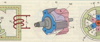
Generator circuit
In order to be able to excite the generator at the right time, without using a battery, you should carefully study the diagram and operating principle of various modifications of the units. An important point is to understand why it is needed in general and exactly what functions it performs.
In simple terms, a generator is a device that serves to convert mechanical energy into electrical energy. It provides power to all electrical consumers in the car and recharges the battery while the engine is running. It is located in the front part of the engine, and operates via a crank shaft. On hybrids, the generator is used as a starter. However, such a scheme is sometimes found on cars with an internal combustion engine that have a stop-start system.
Based on this, we can conclude that generators come in two types, differing in design. Their main difference is how the rectifier unit, drive pulley and fan are located. In addition, generators with different circuits also differ in overall dimensions. The main parameters, regardless of the type, remain the same - they all have a rotor (inductor), stator, etc. in their design.
Below is a diagram of a domestically produced generator. It is found on almost all car models of our production.
And this is a more modern scheme, often found on VAZ from “eight” and above.
Now let's look at the generator connection diagram and how it works.
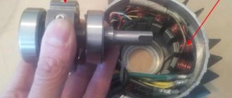
The main task performed by the generator rotor is to create a magnetic field. For these purposes, the shaft has an exciter winding (or VO). It is located on the protrusions of the “plus” halves. The shaft also has a contact group, which consists of two copper rims. Voltage passes through them to the excitation winding; for this they are soldered to the VO contacts.
Important! Sometimes there are rings made of other metals, such as brass or steel.
In addition, the fan impeller is also installed on the shaft. The drive pulley (VPD) is also attached there. Another important rotor component is the bearing.
Regarding the functions of the stator, it converts direct voltage into alternating voltage and consists of a metal core made up of plates and windings. The stator has 46 special slots into which the winding is placed. It allows you to accommodate three windings, so you can get a three-phase connection.
The rectifier unit is used to convert the current produced by the generator from alternating to direct for its subsequent supply to consumers. The block consists of six semiconductor diodes, two for each phase - plus and minus of the generator.
Brushes are needed to transfer the generated current to the exciter rings. They consist of a graphite element, brushes, springs for holding and pressing. On modern generators this unit is combined with the regulator into a single unit.
“Chocolate” is necessary to maintain generator currents at specified values. Today you can find electronic or hybrid regulators. In the hybrid design, the circuit contains radio components and electrical appliances. Electronic parts are made using TMT technologies.
The generator drive operates thanks to the rotation of a belt drive. This gives the same rotation speed to the inductor, which is required for its normal operation.
Hence, in most generator models, the excitation winding is connected by a separate group, which consists of two semiconductor diodes. The diode circuit is more often called a rectifier, and prevents current from flowing from the battery back through the circuit to the generator when the engine is stationary.
Worth knowing. When connecting the winding with a star circuit, two additional power diodes are installed on the zero terminal, this allows you to increase the generator power by 15%. The rectifier unit is installed on the generator using soldering or fixed mechanically.
The regulator is an extremely important part in the generator circuit; it is responsible for stabilizing the voltage when the crankshaft rotation speed changes. This process is completely automatic and occurs by acting on the excitation winding. That is, the regulator is responsible for the voltage frequency and pulse duration.
Interesting. The regulator changes the current supplied to the battery due to thermal voltage compensation. Simply put, the warmer it is, the less current flows to the battery.
Adjustment and load characteristics
The control characteristic iв = f(I) at U = const and n = const and the load characteristic U = f(iв) at I = const and n = const are removed in the same way as for the independent excitation generator. Since iв and Ra × iв are small, the voltage drop from iв in the armature circuit has practically no effect on the voltage at the generator terminals. Therefore, the indicated characteristics are almost the same as those of the independent excitation generator. Constructing these characteristics using x. X. X. and the characteristic triangle are also produced in a similar way.
In conclusion, it can be noted that the characteristics and properties of independent and parallel excitation generators differ little from each other. The only noticeable difference is a slight discrepancy in external characteristics ranging from I = 0 to I = In. The greater discrepancy between these characteristics when I is much larger than In does not matter, since machines, as a rule, do not operate in such operating conditions.
Source: Woldek A.I., “Electrical machines. Textbook for technical schools" - 3rd edition, revised - Leningrad: Energy, 1978 - 832 p.