Author: Evgeny Zhivoglyadov. Date of publication: January 29, 2013. Category: Articles.
The properties of generators are analyzed using characteristics that establish dependencies between the main quantities that determine the operation of generators. These basic quantities are: 1) terminal voltage U, 2) excitation current iв, 3) armature current Ia or load current I, 4) rotation speed n.
Typically generators operate at n = const. Therefore, the main characteristics of generators are determined at n = nn = const.
There are five main characteristics of generators: 1) no-load, 2) short circuit, 3) external, 4) regulation, 5) load.
All characteristics can be determined both experimentally and by calculation.
Let's consider the main characteristics of an independent excitation generator.
Idle characteristics
The no-load characteristic (x. x. x.) U = f (iв) at I = 0 and n = const determines the dependence of the voltage or electromotive force (emf) of the armature Ea on the excitation current during no-load (I = 0, P2 = 0). The characteristic is measured experimentally according to the diagram in Figure 1, and with the switch turned off.
Figure 1. Schemes of generators and motors of independent (a), parallel (b), series (c), mixed (d) excitation (solid arrows - current directions in generator mode, dashed - in motor mode)
| Figure 2. Idle characteristics of the independent excitation generator |
It is advisable to start taking the characteristics from the maximum value of the excitation current and the maximum voltage U = (1.15 – 1.25) Un (point a of the curve in Figure 2). As iв decreases, the voltage decreases along the descending branch of the ab characteristic, first slowly due to saturation of the magnetic circuit, and then faster. At iв = 0, the generator develops a certain voltage U00 = Vol (Figure 2), usually equal to 2 - 3% of Un, due to the residual magnetization of the poles and the yoke of the inductor. If you then change the excitation polarity and increase iв in the opposite direction, starting from iв = 0, then at some iв < 0 the voltage will drop to zero (point c, Figure 2), and then U will change sign and increase in absolute value along the вг branch X. X. X. When the current iв and voltage U reach the same absolute value at point g as at point a, we reduce the current iв to zero (point e), change its polarity and increase it again, starting from iв = 0. In this case, U changes along the branch dea x. X. X. As a result, let's return to point a characteristics. H. x. X. has the appearance of a narrow hysteresis loop due to the phenomenon of hysteresis in the magnetic circuit of the inductor.
When removing x. X. X. The current iв must be changed only in the direction indicated by the arrows in Figure 2, since otherwise the points will not fall on this hysteresis loop, but will be scattered.
Middle dashed x. X. X. in Figure 2 represents the calculated x. X. x., which on a certain scale repeats the magnetic characteristic of the generator, and from it the saturation coefficient of the machine kμ can be determined.
The idle speed characteristic makes it possible to judge the saturation of the machine’s magnetic circuit at rated voltage, to check the compliance of the calculated data with the experimental ones, and forms the basis for studying the operational properties of the machine.
Details about the operating algorithm
The operating principle of the generator is based on a simple physical phenomenon called electromagnetic induction . The bottom line is this: If a magnetic field is applied to a multi-turn winding made of copper wire, changing direction with a certain frequency, then an alternating current of the same frequency will appear at the output of the coil. All that remains is to create the mentioned field around the stator windings that generate voltage.
In practice, electricity generation occurs according to the following algorithm:
- The source of the alternating magnetic field of a car electric generator is a self-exciting winding located on the rotor. To initially magnetize the wedge-shaped bushings, a low-power impulse from the battery is applied to them.
- After starting the engine and reaching a certain crankshaft speed, the stator windings release alternating current, rectified by power diodes. From this moment on, the rotor winding is powered by the generator itself, that is, self-excitation occurs. An external power supply is no longer required.
- Direct current from the diode bridge is supplied to the relay-regulator unit. Since the voltage value “jumps” along with engine speed, the task of the electronics is to stabilize the differences in the range from 13.8 to 14.7 V.
- In addition, voltage is supplied to recharge the battery and the vehicle's on-board network.
The voltage regulator relay can be part of the generator set or used as a separate unit.
The current in the stator windings arises as a result of the rotation of the alternating magnetic field created by the rotor coil . The faster the shaft rotates, the higher the output voltage and frequency. Conversion to DC is provided by semiconductors (diodes) mounted on the heatsink plate and driven by a fan drive.
brushless generator circuit allows you to power the stator winding without an external power source. The magnetization of steel bushings begins at low shaft rotation speeds due to the special design of the rotor and additional coil . Therefore, when starting a car with a discharged battery from the pusher, the crankshaft revolutions are enough for the electric generator to start working.
Short circuit characteristic
| Figure 3. Short circuit characteristics of the independent excitation generator |
The short circuit characteristic (short circuit) I = f (iв) at U = 0 and n = const is removed when the output terminals of the generator armature circuit are short-circuited. Since U = 0, then, according to the expression
(voltage equation U at the generator terminals), Ea = Ia × Ra and since Ra is small, then under the experimental conditions e. d.s. Ea should also be small. Therefore, it is necessary to exercise caution and begin removing x. k.z. from the minimum values of iв so that the armature current does not receive an unacceptably large value. Usually they remove x. k.z. up to I = (1.25 – 1.5) In. Since when removing x. k.z. the electromotive force is small and therefore the flow is small and the machine is not saturated, then the dependence I = f (iв) is almost linear (Figure 3). When iв = 0, due to the presence of residual magnetic flux, the current I is not equal to 0 and in large machines is close to the rated value and even greater than it. Therefore, before removing x. k.z. It is advisable to demagnetize such a machine by feeding the excitation winding at idle speed with such an excitation current in the opposite direction, at which U = 0. In a demagnetized machine x. k.z. starts from zero (dashed line in Figure 3) If x. k.z. removed without first demagnetizing the machine (solid line in Figure 3), then it is also advisable to move it parallel to itself to the origin of coordinates (dashed line in Figure 3).
Terminal markings on the housing
When performing self-diagnosis with a multimeter, the owner needs information about how the terminals on the generator box are marked.
There is no single designation, but all manufacturers adhere to general principles:
- from the rectifier there is a “plus”, designated “+”, 30, V, B+ and BAT, a “minus”, designated “-”, 31, D-, B-, E, M or GRD;
- terminal 67, W, F, DF, E, EXC, FLD comes from the field winding;
- the “positive” wire from the additional rectifier to the control lamp is marked D+, D, WL, L, 61, IND;
- the phase can be recognized by a wavy line, the letters R, W or STA;
- the zero point of the stator winding is designated as “0” or MP;
- the regulator relay terminal for connection to the “plus” of the on-board network (usually to the battery) is designated 15, V or S;
- the ignition switch wire must be connected to the voltage regulator terminal marked IG;
- The on-board computer is connected to the regulator relay output marked F or FR.
There are no other symbols, and the ones listed above are absent on the entire generator body, as they are found on all existing modifications of electrical appliances.
Characteristic (reactive) triangle
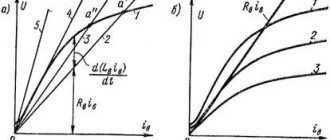
The characteristic (reaction) triangle determines the reaction of the armature and the voltage drop in the armature circuit. It is constructed to find the armature reaction from experimental data and is also used to construct some characteristics of the machine if they cannot be determined experimentally. The characteristic triangle can be constructed from experimental data using x. X. X. and any other main characteristics of the machine, as well as according to calculated data. Let us consider here its construction using x. X. X. their. k.z., for which we turn to Figure 4, where x is shown. k.z. I = f (iв) (straight line 1) and the initial, straight-line part x. X. X. U = f (iв) (line 2), passing through the origin.
Let's construct a characteristic triangle for the rated current of the machine Ia = I = In, which is x. k.z. corresponds to point a and point b on the abscissa axis (Figure 4, a). Let's construct a segment bv on straight line ab, equal on the scale of line 2 to the voltage drop in the armature circuit Iн × Ra, and connect a point in the horizontal line with point r on x. X. X. Then triangle bvg will be a characteristic triangle. The horizontal leg rg of this triangle represents the magnetizing force of the armature reaction on the scale of the excitation current, which can be proven as follows.
| Figure 4. Construction of the characteristic triangle in the case of demagnetizing (a) and magnetizing (b) armature reaction |
Section 0b in Figure 4, a is equal to the current iв required to obtain current I = In during a short circuit. In this case, e must be induced in the armature. d.s. Ea = Iн × Ra, equal to the segment gd, which requires an excitation current 0d = iе at no-load. Thus, the difference 0b - 0d = db = iva between the actual current iv = 0b during a short circuit and the current iе = 0d during no-load can only be due to the influence of the current in the armature and should therefore express the magnetizing reaction force of the armature on the scale of the excitation current iв .
Figure 4, a corresponds to the case of a demagnetizing reaction of the armature (iа is greater than 0), and Figure 4, b – to the case of a magnetizing reaction of the armature (iа is less than 0). In the latter case x. the short circuit, naturally, should rise steeper. For other values of armature currents (I ≠ Iн), the legs of the triangle bvg change almost proportionally to the armature current, since the nonlinearity of the brush contact resistance has little effect.
Since under the conditions of removing x. k.z. Since the magnetic circuit of the machine is not saturated, the characteristic triangle constructed in this way takes into account only the longitudinal reaction of the armature, caused by a random or deliberate shift of the brushes from the geometric neutral and the deviation of the commutation from the rectilinear one. When installing brushes on a geometric neutral, the leg of the triangle iva = db is equal to the magnetizing force of the switching reaction of the armature (on a scale iv) and characterizes the quality of commutation (in Figure 4, a - slow commutation and in Figure 4, b - accelerated). When the brushes are in neutral and the commutation is rectilinear, iva = db = 0 and the triangle bvg degenerates into a vertical straight line.
To construct a characteristic triangle taking into account the influence of the transverse reaction of the armature, you can use x. X. X. and external, adjustment or load characteristics. Usually the load characteristic is used.
How does an electric generator work?
The main part of the device is the housing , consisting of two covers and made of aluminum alloy , which ensures effective removal of excess heat. The casing is equipped with a mounting flange or boss with a through hole for a long bolt (depending on the car brand). In general, the drive device looks like this:
- The front and rear covers of the housing are fastened with screws, and a stationary stator winding is attached to them on the inside.
- The ends of the covers have holes into which the rotor shaft bearings are pressed. There are also ventilation holes on the sides that serve to cool the inside of the generator.
- The rotor, rotating inside the housing on bearings, is a shaft with a second winding and two metal bushings with wedge-shaped notches. From the side of the front cover, the drive pulley is screwed to the shaft using a nut.
- Outside the back cover there are copper slip rings and graphite brushes inserted into special sockets - brush holders. Nearby, on a horseshoe-shaped board, there is a rectifier circuit using diodes (otherwise known as a diode bridge).
- The current-transmitting elements of the rotor (brushes, rings) and the diode circuit are covered from the outside with a protective casing with numerous holes for cooling. An impeller is attached to the rear end of the shaft (below the housing), which forces air through the unit housing.
The design of the electric current generator has changed little since its invention. Designed to convert rotational energy into electricity, this unit features a sophisticated design and high efficiency. The efficiency of the device is 98-99%.
Since current-carrying sliding contacts (brushes) are the weak link of the structure and wear out quickly, most modern generators use a brushless method of current transmission. The technological process involves a sprocket mounted on the shaft and an additional winding connected from the inside to the end of the tail cover.
Despite the apparent complexity of the design of a car electric generator , disassembling it is quite simple. To remove the rotor, simply unscrew the casing and the screws holding the 2 covers together, after first removing the drive pulley.
External characteristics of the generator
The external characteristic of the independent excitation generator U = f (I) with iв = const and n = const (Figure 5) determines the dependence of the generator voltage on its load under natural conditions, when the excitation current is not regulated. As I increases, the voltage U drops slightly for two reasons: due to the voltage drop in the armature circuit I × Ra and a decrease in e. d.s. Ea due to a decrease in flow under the influence of the transverse reaction of the armature (with brushes at the geometric neutral). With a further increase in I, the voltage will begin to fall faster, since under the influence of the armature reaction the flux decreases and the operating point shifts to a steeper falling section of the machine’s magnetization curve.
| Figure 5. External characteristics of the independent excitation generator |
It is recommended to take the external characteristic at such an excitation (iв = iвн), when at I = Iн also U = Un (nominal mode). When switching to idle (I = 0), in this case the voltage increases by a very specific amount ΔUn (Figure 5), which is called the nominal change in generator voltage . In independent excitation generators
The external characteristic (in the left quadrant of Figure 6) can also be constructed using x. X. X. (in the right quadrant of Figure 6) and the characteristic triangle. To do this, let us draw a vertical straight line ab in Figure 6, corresponding to the given current iв = const. Then ab =0b represents U at I = 0 and determines the starting point of the external characteristic.
Let us then place in Figure 6 the characteristic triangle where, constructed on the appropriate scales for I = In, so that its vertex r lies on x. X. x., and leg de – on straight ab. Then the segment ae = zhz will be equal to U for I = In, which can be proven as follows. If U = ae, then Ea = U + In × Ra = ae + ed = ad = ur and to create such an e. d.s. at idle, the excitation current required is ive = 0u. When under load, the excitation current must be increased by the amount iva = gd = ia to compensate for the demagnetizing reaction of the armature. The required total excitation current in this case iв = iе + iа = 0у + яа = 0а exactly corresponds to the given one, which was what needed to be proven.
If we accept that the legs, and therefore the hypotenuse of the characteristic triangle, change in proportion to I, then to obtain other points of the external characteristic it is enough to draw in Figure 6 between x. X. X. and straight line ab inclined segments of straight lines (hypotenuse of new characteristic triangles), parallel to the hypotenuse ge. Then the lower points of these segments (on straight line ab) will determine the value of U at currents
and so on.
By moving these points horizontally to the left quadrant of Figure 6 for the corresponding values of I and connecting them with a smooth curve, we obtain the desired external characteristic U = f (I).
| Figure 6. Construction of the external characteristic of an independent excitation generator using the no-load characteristic and the characteristic triangle |
In fact, the horizontal leg of the characteristic triangle does not grow in proportion to I as U decreases. Therefore, the real external characteristic deviates somewhat to the side from the constructed one, as shown in the left quadrant of Figure 6 by the dashed line.
The external characteristic point with U = 0 determines the value of the short circuit current of the machine when fully excited. Since Ra is small, this current is 5–15 times higher than In. Such a short circuit is very dangerous, as a circular fire occurs, as well as large mechanical forces and torques. Therefore, under operating conditions, generators and engines of medium and high power are protected by high-speed automatic switches in the armature circuit, which limit the duration of the short circuit and disconnect the machine from the network within 0.01 - 0.05 s after the start of a sudden short circuit. However, these switches do not protect the machine if there is a short circuit inside the machine.
If there are experienced x. X. X. and external characteristic and if Ra is known, then by constructing in Figure 6 in the reverse order, one can obtain characteristic triangles taking into account real saturation conditions for any values of U and Ea.
Possible faults
A car generator is a highly reliable device. Possible reasons for its inoperability are divided into two groups, according to the source of the problem.
Mechanical
The cause of malfunctions belonging to this group is mechanical wear as a result of operation. Mechanical faults are detected quickly, as they are accompanied by knocking or other noise.
To eliminate the malfunction, worn parts are replaced with working ones.
Generator parts whose wear leads to mechanical failures:
- pulley;
- friction bearing;
- copper-graphite brushes;
- drive belt.
Regulating characteristic
The regulation characteristic iв = f (I) with U = const and n = const shows how the excitation current needs to be adjusted so that the generator voltage does not change when the load changes (Figure 7). With an increase in I, the current iв must be increased slightly in order to compensate for the influence of the voltage drop Ia × Ra and the armature reaction.
| Figure 7. Regulating characteristic of an independent excitation generator |
When moving from no-load with U = Un to the rated load I = In, the increase in excitation current is 15 - 25%.
The construction of the control characteristic (the lower quadrant of the figure according to x. x. x. (the upper quadrant of the figure and the characteristic triangle) is carried out as follows. For a given U = 0a = vb = const, the value of iв at I = 0 is determined by point b. The characteristic triangle where for the rated current Let us arrange it so that its vertices r and e are respectively on x.x.x. and straight line abe.Then the segment 0zh = ae determines the value of iв for I = In, which can be proven in the same way as was done in the case of constructing an external characteristic. To obtain other points of the characteristic, it is enough to draw line segments parallel to the hypotenuse r between the curve x. x. hypotenuse ge, as in the previous case. By moving these points vertically down, to the lower quadrant of Figure 8, to the level of the corresponding values of I, we obtain the points of the adjustment characteristic. Taking into account the changing saturation conditions, the actual experimental control characteristic will have the form shown in the lower quadrant of Figure 8 with a dashed line.
| Figure 8. Construction of the regulating characteristic of an independent excitation generator using the idle characteristic and the characteristic triangle |
By inverse construction, if x is given. X. X. and the adjustment characteristic, a characteristic triangle can be obtained.
Kinds
There are two main types of car generators:
- Constant, voltage of a certain polarity is created directly on the windings;
- Alternating current, since a constant voltage is still required, the generator is equipped with an internal solid-state rectifier.
Currently, only the second type is used, since it has undeniable advantages; in addition, its windings produce three-phase voltage, which makes it easier to smooth out waves and allows more efficient use of the weight and dimensions of the device.
Load characteristic
The load characteristic U = f (iв) with I = const and n = const (curve 2 in Figure 9) is similar in appearance to x. X. X. (curve 1 in Figure 9) and passes slightly below x. X. X. due to the voltage drop in the armature circuit and the influence of the armature reaction. H. x. X. represents the limiting case of the load characteristic when I = 0. Usually the load characteristic is taken at I = In.
Let us explain how, using characteristics 1 and 2 of Figure 9, you can construct a characteristic triangle. Let 0a correspond to the value U for which it is desirable to construct a triangle (for example, U = Un). Then we draw a horizontal line ab and from point b on the load characteristic we plot upward the segment bv = I × Ra, where I is the current at which the load characteristic is removed. Drawing from a point to a horizontal segment of a straight line until it intersects at point z with x. X. x., we obtain the horizontal leg gv of the desired triangle gvb. The proof of the validity of such a construction can be developed by analogy with the proof of the construction of an external characteristic (see Figure 6).
| Figure 9. Load characteristic of the independent excitation generator |
If the characteristic triangle constructed in this or that way is moved in Figure 9 parallel to itself so that its vertex r slides along x. X. x., then its vertex b will outline the load characteristic (dashed curve in Figure 9). This characteristic will diverge somewhat from experimental characteristic 2, since the size of the core leg will change due to changes in saturation conditions.
Point d in Figure 9 corresponds to a generator short circuit.
All characteristics of generators can be depicted both in absolute values and in relative units. In the latter case, the characteristics of machines of the same type, even if of different power, built in relative units, differ little from each other.
| Figure 10. Shift of brushes from neutral in the presence of additional poles |
Effect of brush shift
The shift of the brushes from the geometric neutral affects the fact that a longitudinal reaction of the armature occurs, changing the flux of the poles. The flux of additional poles will induce e. d.s. not in the switched sections, but in the working sections of the parallel armature branches. When turning the brushes against the direction of rotation of the armature (Figure 10), this will cause an increase in e. d.s. anchor, and with a shift in the direction of rotation - a decrease in e. d.s. In the first case, the external characteristic (see Figure 5) will fall more steeply with increasing I. In the presence of additional poles, a commutation disorder occurs in both cases.
The effect of brush displacement on other characteristics can easily be analyzed in a similar way.
Source: Woldek A.I., “Electrical machines. Textbook for technical schools" - 3rd edition, revised - Leningrad: Energy, 1978 - 832 p.