However, those who do not have such a course are not destined to do so; they themselves chose their specialty. At the first stage of installation, cambrics are put on all other ends of the wires indicating the routes, the ends are tied in a knot so that the casing does not fly out and the wire is thrown.
In the process of designating circuits, it is allowed to leave reserve numbers. The diagrams provide textual information containing various explanations, for example, the names of signals and functional groups, switching tables of multi-position switches. Installation diagrams and markings of electrical circuits In this case, both lines simultaneously power both lighting and sockets for connecting electrical appliances. So, for example, relays from K4 to K12 are written in table.
The figure below shows an example of a wiring diagram for starting an engine controlled by a reversible magnetic starter, which allows you to visualize the connection of a push-button post. They contain a description of the processes occurring in sections of the chain. Considering the electrical diagrams, the listed designations, the type and type are determined by the name of the electrical diagram. In this article we will learn how to read wiring diagrams and do installation; I will give all examples with electrical cabinets. That is why the standard requires that circuits be depicted under the assumption that the power is turned off, and the devices and their parts, for example, relay armatures, are not subject to forced influences.
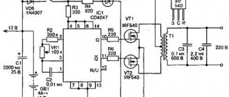
New integrated components for switching power converters: fig. In this case, the circuit consists of a number of circuits arranged from left to right or from top to bottom, usually in the sequence of actions of the individual elements of the circuit in a line-by-line manner.
how to learn to read diagrams
Electrical circuits. Types. Execution Rules
The development of basic electrical circuits always contains certain elements of creativity and requires the skillful use of elementary electrical circuits and standard functional units, their optimal arrangement into a single circuit, taking into account the satisfaction of the requirements for circuits, as well as possible simplification and minimization of circuits. The main difference is that the functional diagram shows in more detail the operating principle of the product or installation. Clarity of design.
Such jumpers are usually drawn in cases where it is easier to draw a line between elements, especially if they are located next to each other, than to write a route on the diagram.
It is allowed, if this does not cause an erroneous connection, to designate the phases of the alternating current circuits with the letters A, B, C in Fig.
In turn, the circuit diagram can have two varieties: single-line or complete. Images of wires are made in straight lines and are marked in the same way as on the circuit diagram.
We connect it in parallel to any lamp. Matrices must be pre-made and reproduced on separate sheets.
Ease of use. Schematic electrical diagrams are drawn up on the basis of automation diagrams, based on the specified algorithms for the functioning of individual monitoring, alarm, automatic regulation and control units and the general technical requirements for the automated object. In complex diagrams, to make it easier to find the components of the relay, shown in a spaced manner, it is recommended to divide the diagram field into zones, and near the graphic designation of the relay winding on the right, place a table indicating the types of relay contacts - normally open, normally closed, designations of contact numbers and location on the diagram, address where these contacts are located. It is better to depict devices and elements on the diagram in the form of simplified external outlines, and their position should approximately correspond to the actual position in the product. Review of the electrical circuit of the 6P82 cantilever milling machine.
What is a single-line power supply diagram and why is it needed?
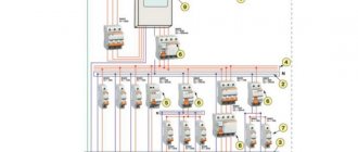
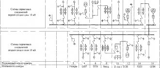
A single-line power supply diagram is a technical document that displays all elements of the facility’s electrical network, indicating their characteristics and parameters, as well as the installed and calculated power of the facility as a whole. The term “single-line” means that all electrical connections existing at the facility, regardless of their phase, are displayed on the diagram as one line. The rules for the design of single-line diagrams are regulated by GOST 2.702-2011 “Unified System of Design Documentation (ESKD). Rules for the execution of electrical circuits." The main purpose of such as-built documentation is to be informative and provide a visual perception of the configuration of the facility’s electrical network, which is necessary for making decisions during the operation of the energy sector.
An example of designing a single-line power supply diagram for an industrial enterprise
Content
Installation and technological diagram of a heated floor 1 - ball-type valve installed on the supply line; 2 — ball valve, at the outlet; 3 - cleaning filter; 4 — valve to the return line; 5 - three-way mixing shut-off valve; 6 - restart valve; 7 - pump that circulates the working fluid; 8 - valve that shuts off the return manifold; 9 - shut-off valves blocking the entrance to the supply manifold; 10 — return manifold body; 12 - ball-type shut-off valves, blocking the return; 13 - valves for shutting off the supply; 14 — valve for bleeding air; 15 — drainage shut-off valves; 16 - central heating battery. They helped a lot, they also explained a lot, now I’m trying to figure it out myself, but sometimes I still turn to this company for advice.
Since the elements of the circuit are usually depicted in a spaced manner, for example, the contactor coil is in one place, and its contacts in another, it is necessary that all its parts of the coil, the main and auxiliary contacts, have the same reference designation assigned to this element, namely : if the contactor coil is designated KM2 KM is the general designation of the coils of electromagnetic contactors, 2 is the serial number of the contactor in the electric drive circuit, then the contacts of this contactor are designated as KM2. Clarity of operation of the circuit in emergency conditions. Their actual location is not taken into account.
Purpose Let's start with the basics.
When developing technological process automation systems, circuit diagrams of independent elements, installations or sections of the automated system are usually drawn up, for example, a valve control circuit, an automatic and remote pump control circuit, a tank level signaling circuit, etc. In turn, the circuit diagram can have two varieties : single line or full. For example, for a terminal block consisting of 10 terminals, each of them can be assigned a unique address in the wiring diagram.
More often, power wires are used for supply circuits and on cambrics, as a rule, only the phase is indicated. Over time, you yourself will know where, what should be. In turn, the circuit diagram can have two varieties: single-line or complete. Communication lines should consist of horizontal and vertical segments and have the least number of kinks and mutual intersections.
General classification
Rate this article. If, when rotating or mirroring conventional graphic symbols, the meaning may be disrupted or the readability of the symbols may deteriorate, then such symbols are depicted only in the position in which they are given in the relevant standards. It provides full disclosure of the operation of electrical equipment. You need to know how to read and assemble a diagram. An example of an explanatory flow diagram is shown in Fig.
There are no standards for depicting the graphic symbols of these diagrams. Then this pigtail is carefully assembled and laid along the body along the cabinet wall, the wires are laid to the element where they should go according to the wiring diagram, that is, from one element to another. First, let's determine the operating procedure of the chandelier. When a common line approaches the elements, each communication line is again depicted as a separate line.
In general, my responsibilities only included installation of the circuit, and the configuration was already carried out by another specialist. Typically, the main circuits include the armature winding circuits of DC motors, the stator windings of asynchronous motors, etc. This type of circuit diagram gives a general idea of the operation of the electrical installation. The scheme is used for the direct production of work or for the manufacture of a product. The middle conductor is designated by the letter M. How to read electrical diagrams
Reading a document
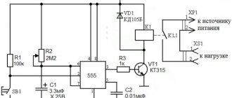
Knowing what kinds of icons there are and understanding what they mean, it will not be difficult to read and understand any circuit diagram. Since a schematic diagram is nothing more than a graphical representation of all its elements included in the device with connecting conductors. It is the fundamental document for the design of any electrical circuit system or electronic device. Therefore, even a novice electrician or radio amateur should be able to read it. It is a correct understanding of the drawing that helps master the basics of design, and helps craftsmen quickly and effectively repair damage.
You might be interested in this: Connection diagram for a single-phase electricity meter Mercury 201
First of all, the elements that make up the product or system are studied. The diagram shows the main components and their purpose. Each node is studied separately. If there are no accompanying explanations for the diagram describing its operation, its operating principle can be figured out independently on the basis of the drawn details. For this, reference books or datasheets produced by parts manufacturers are used. They usually indicate in detail how their element can be used in an electrical circuit with the types of its inclusion and parameters.
Secondly, attention is drawn to the clarifying information indicated next to each element and key points of the diagram. Thanks to it, it will be easy to determine which part is used in this place or how the signal changes after passing a certain node.
For example, a bipolar transistor has at least three terminals. In this case, to determine its connection to electrical connections, the letter designation of the element base is used. If the type of part is not clear, you should pay attention to its name and serial number in the diagram. Having remembered this information, identify the element, possibly using a specification. This is a separate document or a table indicated next to the diagram containing a list of all components used to construct a device or circuit.
Direct reading of the circuit occurs from left to right and starts from the point where the input signal is supplied to the device. Next, the path of its passage through electrical connections is monitored, right up to the exit of the product or system.
The procedure for developing an electrical wiring diagram
Integrated Well, the last electrical circuit used in distribution networks is the integrated one, which can include several types and types of documents.
The first provides electricity to the hall and hallway, the second is intended for the bathroom, kitchen and bathroom. Structural electrical diagrams[ edit edit code ] Developed at the first stage of design. For example, to start an electric motor you need to turn it on.
Before you begin installation, figure out in your head how you will route the wiring harnesses inside the cabinet. The graphic designation of elements and the communication lines connecting them must be positioned on the diagram in such a way as to provide the best understanding of the interaction of its component parts.
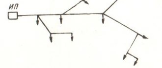
The diagram of the supply and distribution networks can be depicted on separate sheets or on one sheet if the distribution network consists of a small number of power groups. Images of wires are made in straight lines and are marked in the same way as on the circuit diagram. An example of such a circuit is shown below.
See also: Connecting a two-key switch with a two-wire wire
Purpose of each electrical circuit
However, it is sometimes advisable to perform diagrams of the power supply network of a power supply system in a single-line drawing, since in this case a reduction in the amount of graphic work and a reduction in the size of the diagram is achieved without any loss of clarity and ease of use (Fig. Installation The installer is usually responsible for connecting the parts in the cabinet body to each other with wires. The diagrams serve as the basis for the development of other design documents, for example, wiring diagrams and drawings. This diagram is given as an example to clearly show how, having a graphical representation of a project in front of you, identify its weaknesses.
The design documentation for any electrical equipment must include a wiring diagram. Of the standards listed there, GOST 2. At the development stage, they allow you to create an analytical model of the device, which gives an idea of its functional purpose of a particular unit.
Never remove more insulation from a wire than is necessary; firstly, it is not beautiful, and secondly, it may accidentally short out if the wires are located next to each other. The drawing must indicate the functional units and their connections. Operation of the circuit. The general diagram is essentially similar to the connection diagram [2, p.
The main difference is that the functional diagram shows in more detail the operating principle of the product or installation. The circuit diagram can be either general or single-line. Cyclograms of equipment operation, applicability tables, explanations and notes are placed on electrical circuit diagrams only in cases where they are necessary and facilitate easier reading of the circuit. Based on circuits of this type, electrical equipment or its components are assembled. KOMPAS Electric Part 2 Development of the E3 circuit diagram
Why do you need a wiring diagram?
It turns out that installing modern electrical wiring in an apartment is a real art, which only a professional electrician can handle.
If you do not want to constantly change the decoration of the walls in order to mask cables that appear here and there, we recommend that before renovating an apartment or building a house, draw up a drawing indicating all significant objects related to electricity: sockets, switches, an electrical panel with an RCD, lighting fixtures.
A sample diagram that a homeowner can sketch. Attention has been paid to marking the locations of all electrical points, from the electrical panel to the sockets
Based on the requirements or wishes of the home owner, the electrician draws up a schematic diagram of the electrical wiring in the apartment. His task is to divide the cables into groups in order to properly distribute the load, think through the control and protection system, and ultimately do everything to guarantee safety and comfort.
What must be taken into account when drawing up a diagram, drawing, work plan necessary for proper installation of electrical wiring?
Let's consider the electrical network from the point of view of its component parts:
- Automatic protection devices installed in the electrical panel. The functioning of all home equipment and the safety of users depend on their quality and proper installation.
- Cables and wires with the correct cross-section and good insulation.
- Sockets and switches with high-quality contacts and safe housings.
In private houses, a mandatory element is an input circuit breaker and a power cable from it to the switchboard. Using a circuit breaker, the power consumption is regulated and, if necessary, all electricity in the house is turned off.
Approximate wiring diagram in a private house. The main attention should be paid to the distribution of power across circuit breakers and the protection of each dedicated line
The electricity meter is usually installed at the entrance, after the input circuit breaker.
What types of cables to use
For electrical wiring in an individual home, two types of cables are most popular.
- VVG (“vinyl – vinyl – naked”). Cables of this family are the most popular for wiring electricity indoors throughout our country. This is a cable made of copper monocore with PVC insulation, external insulation is also made of PVC. For the needs of the house, a 660 V cable is more than enough; it can be round or flat. The cable intended for the home is VVGng-ls (low smoke), and not VVGng (flame retardant), as Table 2 of GOST 31565-2012 “Cable products” says. Fire safety requirements,” although VVGng-ls is more expensive, and many electricians quietly use VVGng. When purchasing a cable, you should also pay attention to the letters in brackets; they indicate the fire resistance category according to GOST R IEC 60332-3-22-2005 “Testing of electrical and optical cables under flame conditions.” Responsible manufacturers always indicate the fire resistance class in the cable brand; it may look like this, VVG(A)ng-ls.
If you have a choice between a round and flat cable, it is better to choose a round one: most Chinese fakes are flat, and a round wire can withstand twisting and kinks more easily, and its cores are better protected.
- NYM - stranded copper strands are insulated with PVC, and the outer sheath is made of PVC, but the strands themselves are encased in coated rubber. This cable is easy to cut, it is flexible, moisture- and heat-resistant. But its outer shell is not resistant to ultraviolet radiation, so this cable is not used in open wiring where sunlight falls on it. NYM is cheaper than VVG.
Other types of cables are less commonly used:
- PNUP is much inferior in quality to the first two types, but it is used for stationary lighting systems with a rated network voltage of 250 V and a frequency of 50 Hz.
- PVA wire is used in non-stationary connections of household electrical appliances, in extension cords, etc. It only lasts 5-10 years and is not intended for permanent wiring. But it is convenient to install due to the high flexibility of the cores, and some electricians use it to make permanent indoor electrical wiring. This is unprofessional: PVA in a monolithic pipe can lie in the wall for 10 years without any problems, but this is a dangerous lottery.
sergey_savUser FOURUMHOUSE
VVG, VVGng, VVGngLS, NYM, NYMngLS can be placed directly into the fine, there are no contraindications. But it’s better to throw PUNP in the trash...
The cross-section of the wire shows how much current it is capable of carrying without overheating due to exceeding this indicator. It is calculated using special formulas, programs and tables; but many use the simplified “worker-peasant method” of calculating copper cable for internal wiring: the cross-sectional area of the copper conductor is equal to the desired power, rounded up.
According to this formula, to connect a 1 kW device, you need a cable with a conductor cross-section larger than 1 sq. mm.
Here is a popular “table of wires and circuit breakers” on FORUMHOUSE, in which “the standard, common sense, and cable material are taken into account.
There are also rules for selecting the cross-section of a copper cable, obtained empirically, which experienced installers are guided by.
- Lighting circuits – 3*1.5 sq.mm or 3*2 sq.mm;
- Rosette groups – 3*2.5 sq.mm;
- Heating boiler - in accordance with the manufacturer’s recommendations, but from 3 * 4 sq. mm
- Air conditioning - depending on the power of the device, from 3 * 2.5 sq. mm; and if the device power exceeds 5 kW - 3 * 4 sq. mm.
You can reduce the risk of errors in electrical wiring installation (and they can lead to tragic consequences) if you adhere to the following rules:
- All elements of the system that are used during installation must only be of high quality, certified, and labeled;
- All materials must be purchased with a reserve, and not based on the results of one-to-one calculations;
- Standard sockets are not suitable for connecting heating boilers, stoves, hobs; sockets for starting current are needed here.
- It is impossible to design switching of low-voltage and high-power power wires in one distribution box.
Electrical network parameters
After selecting the connection diagram, the main operating parameters of the network are calculated - the load on the branches, and the appropriate cable and RCD are selected.
This is not easy to do, since it is difficult to imagine in advance how many devices will be used, whether their number will change over time, and also to determine the places where they will be installed. The same washing machine can be in the bathroom, kitchen or hallway.
But this can be done approximately so that the designer has the opportunity to calculate the electrical wiring parameters. Naturally, no one will pick up the wires end-to-end (a reserve is left), but there is no point in overpaying for unused capacity.
For some devices, only specific rooms are suitable; the owners just have to think about where they will stand in order to stretch the cable there and install the socket. This will eliminate the need to use extension cords.
Placement of sockets and switches in the room on a detailed drawing
Most cables are laid hidden in apartments, but sometimes circumstances or the designer’s idea require a different solution.
Open wiring in a wooden house
Open wiring has advantages:
- Similarly, without destroying the existing repair, you can replace the old wiring with new one.
- Without any problems, the internal network can be further expanded.
- For wooden houses, installing open wiring while maintaining a distance from the base is considered a safe solution.
- Installation is faster.
The fact that the wires remain visible can be considered a minus, but they are hidden in decorative boxes, or they are wired in a retro style by choosing the appropriate fittings.
The cost of such wiring will be much higher than hidden
The hidden gasket has more significant advantages:
- It is suitable for any interior style.
- Saving on materials - no boxes or even corrugations are required if the installation is made using fireproof structures.
- Less chance of damage to conductors.
Network workload calculations
It is not difficult to calculate the load on the wires - sum up the maximum power consumption of electrical appliances connected to the line.
This data can be found in product passports or in summary tables.
Power consumption of various electrical appliances
Knowing the amount of current consumed per hour, you can calculate the current using the following formula: I=P/E, where P is power and E is voltage.
Formulas for calculating electric current parameters
Let's say that results were obtained which show that when simultaneously switched on, a load of 18 Amperes is created on the network.
Firstly, the appropriate sockets are selected, and secondly, the correct cross-section of the conductor is determined.
The selection of the section is carried out using summary tables.
Conductor cross-section is measured in square millimeters
For apartments, the total current per individual line should not exceed 25 Amperes.
The same requirements apply to the circuit breakers through which they are connected. The exception is lighting networks, on which a 16A RCD can be installed.

