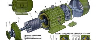
The main functions of a vector frequency generator and its scope of application
The main function of frequency converters (FCs) is to equalize the frequency of industrial current to that required by the motor. The main tasks of a directed emergency are interaction with the electric motor from the moment of starting to a complete stop, as well as protecting the mechanism and saving energy.
A vector frequency generator has the following advantages:
- the most complete accounting of the dynamics (torque, frequency, speed, angle of rotation) of an asynchronous motor with increased efficiency;
- stable control of torque on the electric motor shaft;
- quick response to load changes, can operate with instantaneous values;
- wide range of frequencies with which you can work. For example, with mechanisms at low speeds (slow speed) or at certain moments;
- copes with any work of a “scalar”.
Vector type frequency drivers are used in various mechanisms and industries:
- in fast-acting systems - roller machines, winches, elevators, special mechanisms, as well as in the production of machine tools;
- in compressors;
- in washing machines in industry;
- in metalworking (in equipment for running in);
- in extruders;
- in printing;
- in equipment for wire production;
- in injection molding machines for injection molding;
- in multi-level car parks.
Thanks to the vector orientation, we obtain stable operation at low rotation speeds.
If you need to perform complex and precise work with variable speed and torque, it is better to choose a vector frequency converter.
Scalar frequency generator: based on the law U/f=const
According to experts from vesper.ru, the simplest, most common and accessible are scalar frequency converters, which control the engine rotation speed using a linear law, which states that the ratio of voltage and frequency is a constant. As a result, the device controls the speed by changing the frequency. Features of scalar devices:
- Relatively low price
- Simplicity of the operating mechanism
- Mainly focused on the “pump” type of load.
Management methods
The vector type of torque control and control has two methods:
- The linear method works with PWM voltage. The regulator operates with averaged discrete values, and not with instantaneous ones. Most processes use space vector modulation. The linear method includes several subtypes:
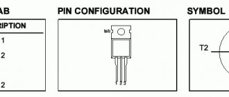
- field-oriented control;
- direct torque control with voltage FDA;
- direct torque control with the flow FDA.
- The nonlinear method is developed as a replacement for the linear method. The main advantages of the nonlinear method are ease of control, no conversion of coordinates and a rotor position sensor is required. This method achieves good dynamics.
Various variable speed control options improve the operation of the electric motor, for example, starting torque, reducing noise levels or torque pulsation.
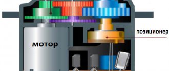
Vector motor control “on your fingers”
— What is vector control? — Keep the current at 90 degrees. The term “vector control” of electric motors is familiar to anyone who has been at least somewhat interested in the question of how to control an AC motor using a microcontroller. However, usually in any book on electric drives the chapter on vector control is somewhere near the end, consisting of a bunch of hairy formulas with references to all the other chapters of the book. Why don’t you want to understand this issue at all? And even the simplest explanations still go through differential equilibrium equations, vector diagrams and a bunch of other mathematics. Because of this, attempts like this appear to somehow turn on the engine without using the hardware. But in fact, vector control is very simple if you understand the principle of its operation “on your fingers”. And then it will be more fun to deal with formulas if necessary.
Let's consider the operating principle of the simplest AC motor - a permanent magnet synchronous machine. A convenient example is a compass: its magnetic needle is the rotor of a synchronous machine, and the Earth’s magnetic field is the magnetic field of the stator. Without an external load (and there is none in the compass, except for friction and fluid that dampens the oscillations of the needle), the rotor is always oriented along the stator field. If we hold a compass and rotate the Earth under it, the needle will spin along with it, doing work to mix the liquid inside the compass. But there is a slightly simpler way - you can take an external magnet, for example, in the form of a rod with poles at the ends, the field of which is much stronger than the Earth’s magnetic field, bring it to the compass from above and rotate the magnet. The arrow will move following the rotating magnetic field. In a real synchronous motor, the stator field is created by electromagnets - coils with current. The winding circuits there are complex, but the principle is the same - they create a magnetic field with the stator, directed in the desired direction and having the required amplitude. Let's look at the following figure (Figure 1). In the center there is a magnet - the rotor of a synchronous motor (the "arrow" of the compass), and on the sides there are two electromagnets - coils, each creating its own magnetic field, one in the vertical axis, the other in the horizontal.
Figure 1. Operating principle of a synchronous electric machine
The magnetic flux of the coil is proportional to the current in it (to a first approximation). We will be interested in the magnetic flux from the stator in the place where the rotor is located, i.e. in the center of the picture (we neglect edge effects, scattering and everything else). The magnetic fluxes of two perpendicularly located coils are added vectorially, forming one common flux for interaction with the rotor. But since the flux is proportional to the current in the coil, it is convenient to draw the current vectors directly, aligning them with the flux. The figure shows some currents Iα
and
Iβ
, creating magnetic fluxes along the α and β axes, respectively.
The total stator current vector Is
creates a codirectional stator magnetic flux.
Those. in fact, Is
symbolizes the external magnet that we brought to the compass, but created by electromagnets - coils with current.
In the figure, the rotor is located in an arbitrary position, but from this position the rotor will tend to rotate according to the stator magnetic flux, i.e. along the vector Is
(the position of the rotor in this case is shown by the dotted line).
Accordingly, if you apply current only to phase α
, say,
Iα
= 1A, the rotor will stand horizontally, and if in β, vertically, and if you apply
Iβ
= -1A, it will turn over 180 degrees.
If current Iα
according to the sine law, and
Iβ
according to the cosine law of time, then a rotating magnetic field will be created.
The rotor will follow it and spin (like a compass needle follows the rotation of a magnet by hand). This is the basic principle of operation of a synchronous machine, in this case a two-phase machine with one pair of pluses. Let's draw a graph of the motor torque depending on the angular position of the rotor shaft and the stator current vector Is
- the angular characteristic of a synchronous motor. This dependence is sinusoidal (Figure 2).
Figure 2. Angular characteristic of a synchronous machine (there is some historical confusion here with the signs of moment and angle, which is why the characteristic is often drawn inverted relative to the horizontal axis).
To obtain this graph in practice, you can put a torque sensor on the rotor shaft, then turn on any current vector, for example, simply apply current to phase α. The rotor will rotate to the appropriate position, which must be taken as zero. Then, through the torque sensor, you need to turn the rotor “by hand”, fixing the angle θ
, which was turned, and the moment that the sensor showed. Those. you need to stretch the “magnetic spring” of the engine through the torque sensor. The largest moment will be at an angle of 90 degrees from the current vector (from the beginning). The amplitude of the resulting maximum torque Mmax is proportional to the amplitude of the applied current vector. If 1A is applied, we get, say, Mmax = 1 N∙m (newton*meter, unit of measurement of torque), if we apply 2A, we get Mmax = 2 N∙m.
From this characteristic it follows that the motor develops the greatest torque when the rotor is at 90° to the current vector. Since, when creating a control system on a microcontroller, we want to obtain the highest torque from the motor with a minimum of losses, and losses, first of all, are the current in the windings, it is most rational to always set the current vector at 90° to the magnetic field of the rotor, i.e. perpendicular to the magnet in Figure 1. We need to change everything the other way around - the rotor does not move towards the current vector we set, but we always set the current vector at 90° to the rotor, no matter how it rotates there, i.e. “nail” the current vector to the rotor. We will regulate the motor torque by the amplitude of the current. The greater the amplitude, the higher the torque. But the rotation frequency, the frequency of the current in the windings is no longer “our” business - what happens, how the rotor rotates, so it will be - we control the torque on the shaft. Oddly enough, this is exactly what is called vector control - when we control the stator current vector so that it is at 90° to the rotor magnetic field. Although some textbooks give broader definitions, to the point that vector control generally refers to any control laws where “vectors” are involved, but usually vector control refers to precisely the above control method.
But how is vector control achieved in practice?
Obviously, first you need to know the position of the rotor so that you have something to measure 90° relative to. The easiest way to do this is by installing the position sensor itself on the rotor shaft. Then you need to figure out how to create a current vector, maintaining the desired currents in phases α
and
β
. We apply voltage to the motor, not current... But since we want to support something, we need to measure it. Therefore, for vector control you will need phase current sensors. Next, you need to assemble a vector control structure in the form of a program on a microcontroller that will do the rest. So that this explanation does not look like an instruction on “how to draw an owl,” let’s continue the dive. You can maintain the current with the microcontroller using a software PI (proportional-integral) current regulator and PWM. For example, a structure with a current regulator for one phase α is shown below (Figure 3).
Figure 3. Current-closed control structure for one phase
Here the current setting iα_back
– a certain constant, the current that we want to maintain for this phase, for example 1A.
The task is sent to the current regulator adder, the disclosed structure of which is shown above. If the reader does not know how the PI controller works, then alas. I can only recommend some of this. The output current regulator sets the phase voltage Uα
.
The voltage is supplied to the PWM unit, which calculates the duty cycle settings (comparison settings) for the PWM timers of the microcontroller, which generate PWM on a four-switch bridge inverter to generate this Uα
.
The algorithm can be different, for example, for positive voltage the PWM of the right rack is proportional to the voltage setting, the lower switch is closed on the left, for negative PWM the left one, the lower switch is closed on the right. Don't forget to add dead time! As a result, such a structure makes a software “current source” at the expense of a voltage source: we set the value iα_set
, and this structure implements it with a certain speed.
Further, perhaps some readers have already thought that the vector control structure is only a small matter away - you need to install two current regulators, one regulator for each phase, and form a task on them depending on the angle from the rotor position sensor (RPS), i.e. e. make something like this structure (Figure 4):
Figure 4. Incorrect (naive) vector control structure
You can't do that. When the rotor rotates, the variables iα_rear
and
iβ_back
will be sinusoidal, i.e. the task for the current regulators will change all the time. The speed of the controller is not infinite, so when the task changes, it does not immediately process it. If the task is constantly changed, then the regulator will always catch up with it, never reaching it. And as the engine rotation speed increases, the lag of the real current from the given one will become larger and larger, until the desired angle of 90° between the current and the rotor magnet ceases to be similar to it at all, and the vector control ceases to be so. That's why they do it differently. The correct structure is as follows (Figure 5):
Figure 5. Structure of vector sensor control for a two-phase synchronous machine.
Here two blocks have been added - BKP_1 and BKP_2: blocks of coordinate transformations. They do a very simple thing: they rotate the input vector by a given angle. Moreover, BOD_1 turns to + ϴ
, and BKP_2 on -
ϴ
.
That's all the difference between them. In foreign literature they are called Park transformations. BKP_2 makes a coordinate transformation for currents: from the stationary axes α
and
β
tied to the motor stator, to the rotating axes
d
and
q
tied to the motor rotor (using the rotor position angle
ϴ
).
And BKP_1 makes the reverse transformation, from setting the voltage along the d
and
q
, it makes the transition to the
α
and
β
.
I don’t provide any formulas for converting coordinates, but they are simple and very easy to find. Actually, there is nothing more complicated than school geometry (Figure 6): Figure 6. Coordinate transformations from the fixed axes α and β tied to the motor stator to the rotating axes d
and
q
axes tied to the rotor
That is, instead of “rotating” the settings of the regulators (as was the case in the previous structure), their inputs and outputs rotate, and the regulators themselves operate in static mode: currents d
,
q
and controller outputs in steady state are constant.
d
and
q
axes rotate together with the rotor (as they are rotated by a signal from the rotor position sensor), while the
q
regulates exactly the current that at the beginning of the article I called “perpendicular to the rotor field”, that is, it is a torque-forming current, and the current
d
is co-directed with the “rotor magnet”, so we don’t need it and we set it equal to zero. This structure is free from the disadvantage of the first structure - the current regulators do not even know that something is spinning somewhere. They work in a static mode: they have adjusted each of their currents, reached the specified voltage - and that’s it, like the rotor, don’t run away from them, they won’t even know about it: all the work of turning is done by coordinate transformation blocks.
To explain “on the fingers” you can give some analogy.
For linear traffic, let it be, for example, a city bus.
It constantly accelerates, then slows down, then goes backwards and generally behaves as it wants: it is an engine rotor. Also, you are in a car nearby, driving in parallel: your task is to be exactly in the middle of the bus: “keep 90°”, you are the current regulators. If the bus changes speed all the time, you should also change the speed accordingly and monitor it all the time. But now we’ll do “vector control” for you. You climbed inside the bus, stood in the middle and held on to the handrail - like the bus, don’t run away, you can easily cope with the task of “being in the middle of the bus.” Similarly, current regulators, “rolling” in the rotating axes d, q of the rotor, live an easy life. The above structure actually works and is used in modern electric drives.
Only it lacks a whole bunch of small “improvements”, without which it is no longer customary to make it, such as compensation for cross-connections, various restrictions, field weakening, etc. But this is the basic principle. And if you need to regulate not the drive torque, but still the speed (the correct angular speed, rotation frequency)? Well then we install another PI controller - a speed controller (RS). We apply a speed command to the input, and at the output we have a torque command. Since the q
is proportional to the torque, then, to simplify things, you can apply the output of the speed controller directly to the input of the
q-
, like this (Figure 7):
Figure 7. Speed controller for vector control Here the ZI, an intensity setter, smoothly changes its output so that the engine accelerates at the desired pace, and does not drive at full current until the speed is set. The current rotational speed ω
is taken from the rotor position sensor handler, since
ω
is the derivative of the angular position
ϴ
. Well, or you can simply measure the time between sensor pulses...
How to do the same for a three-phase motor? Well, actually, nothing special, we add another block and change the PWM module (Figure 8).
Figure 8. Vector sensor control structure for three-phase synchronous machine
Three-phase currents, just like two-phase ones, serve one purpose - to create the stator current vector Is
, directed in the desired direction and having the desired amplitude. Therefore, three-phase currents can simply be converted into two-phase, and then leave the same control system that has already been assembled for a two-phase machine. In English-language literature, such a “recalculation” is called Clarke transformation (Edith Clarke is her), in our country it is called phase transformations. In the structure in Figure 8, accordingly, this operation is performed by a phase transformation block. They are done again using the school geometry course (Figure 9):
Figure 9. Phase conversions - from three phases to two.
For convenience, we assume that the amplitude of the vector Is is equal to the amplitude of the current in the phase . I think no comments are needed. A few words about the current of phase C. There is no need to install a current sensor there, since the three phases of the motor are connected in a star, and according to Kirchhoff’s law, everything that flows through two phases must flow out of the third (unless, of course, there is a hole in your motor insulation, and half did not leak somewhere onto the housing), therefore the current of phase C is calculated as the scalar sum of the currents of phases A and B with a minus sign. Although a third sensor is sometimes installed to reduce measurement error.
A complete rework of the PWM module is also required. Typically, a three-phase six-switch inverter is used for three-phase motors. In the figure, the voltage command still arrives in two-phase axes. Inside the PWM module, using reverse phase transformations, this can be converted into voltages of phases A, B, C, which must be applied to the motor at this moment. But what to do next... Options are possible. A naive method is to set a duty cycle for each inverter rack proportional to the desired voltage plus 0.5. This is called sine wave PWM. This is exactly the method that the author used in habrahabr.ru/post/128407. Everything is good in this method, except that this method will underutilize the voltage inverter - i.e. the maximum voltage that will be obtained will be less than what you could get if you used a more advanced PWM method.
Let's do the math. Let you have a classic frequency converter, powered by an industrial three-phase network 380V 50Hz. Here 380V is the linear (between phases) effective voltage. Since the converter contains a rectifier, it will rectify this voltage and the DC bus will have a voltage equal to the amplitude linear voltage, i.e. 380∙√2=540V DC voltage (at least without load). If we apply a sinusoidal calculation algorithm in the PWM module, then the amplitude of the maximum phase voltage that we can achieve will be equal to half the voltage on the DC bus, i.e. 540/2=270V. Let's convert into effective phase: 270/√2=191V. And now to the current linear: 191∙√3=330V. Now we can compare: 380V came in, but 330V came out... And you can’t do anything else with this type of PWM. To correct this problem, the so-called vector type PWM is used. Its output will again be 380V (ideally, without taking into account all voltage drops). The vector PWM method has nothing to do with vector control of an electric motor. It's just that its rationale again uses a little school geometry, which is why it's called vector. However, his work cannot be explained on the fingers, so I will refer the reader to books (at the end of the article) or to Wikipedia. I can also give you a picture that slightly hints at the difference in the operation of sinusoidal and vector PWM (Figure 10):
Figure 10. Changing phase potentials for scalar and vector PWM By the way, what position sensors are used for vector control?
There are four types of sensors most commonly used. These are a quadrature incremental encoder, a Hall element-based encoder, an absolute position encoder, and a synchronous encoder. The quadrature encoder
does not give out the absolute position of the rotor - by its impulses it only allows you to determine how far you have traveled, but not where and from where (how the beginning and end are related to the location of the rotor magnet).
Therefore, it is not suitable for vector control of a synchronous machine. Its reference mark (index) saves the situation a little - there is only one per mechanical revolution, if you reach it, then the absolute position becomes known, and from it you can already count how much you have traveled using a quadrature signal. But how to get to this mark at the beginning of work? In general, this is not always convenient. The Hall element sensor
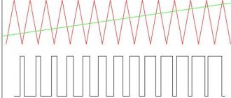
is a crude sensor. It produces only a few pulses per revolution (depending on the number of Hall elements; for three-phase motors there are usually three, i.e. six pulses), allowing you to know the position in absolute value, but with low accuracy. The precision is usually enough to keep the angle of the current vector so that the motor at least moves forward and not backward, but the torque and currents will pulsate. If the engine has accelerated, then you can start programmatically extrapolating the signal from the sensor over time - i.e. construct a linearly varying angle from a rough discrete angle. This is done based on the assumption that the motor rotates at approximately constant speed, something like this (Figure 11):
Figure 11. Operation of a Hall element position sensor for a three-phase machine and extrapolation of its signal
Often a combination of an encoder and a Hall effect sensor is used for servo motors. In this case, you can make a single software module for processing them, eliminating the disadvantages of both: do the angle extrapolation given above, but not by time, but by marks from the encoder. Those. An encoder operates inside the Hall sensor from edge to edge, and each Hall edge clearly initializes the current absolute angular position. In this case, only the first movement of the drive will be non-optimal (not at 90°), until it reaches some front of the Hall sensor. A separate problem in this case is the processing of non-idealities of both sensors - rarely does anyone arrange the Hall elements symmetrically and evenly...
Even more expensive applications use an absolute encoder
with a digital interface (absolute encoder), which immediately provides the absolute position and allows you to avoid the problems described above.
If the electric motor is very hot, and also when increased accuracy of angle measurement is required, use an “analog” synchro sensor
(resolver, rotating transformer).
This is a small electrical machine used as a sensor. Imagine that in the synchronous machine we considered in Figure 1, instead of magnets, there is another coil to which we apply a high-frequency signal. If the rotor is horizontal, then the signal will be induced only into the stator coil of phase α
, if vertically, then only into
β
, if you turn it 180, then the phase of the signal will change, and in intermediate positions it will be induced both here and there according to the sine/cosine law.
Accordingly, by measuring the signal amplitude in two coils, the position can also be determined from the ratio of this amplitude and the phase shift. By installing such a machine as a sensor to the main one, you can find out the position of the rotor. There are many more exotic position sensors, especially for ultra-high precision applications such as electronic chip making. There, any physical phenomena are used just to find out the position as accurately as possible. We will not consider them. As you understand, vector control is quite demanding - give it position sensors, current sensors, PWM vector control, and no microcontroller to calculate all this mathematics. Therefore, for simple applications it is simplified. To begin with, you can eliminate the position sensor by making sensorless vector control. To do this, use a little more mathematical magic, located in the yellow rectangle (Figure 12):
Figure 12. Structure of sensorless vector control
An observer is a block that receives information about the voltage applied to the motor (for example, from a job on the PWM module) and about the currents in the motor from sensors. Inside the observer there is a model of an electric motor, which, roughly speaking, tries to adjust its currents in the stator to those measured from a real motor. If she succeeded, then we can assume that the position of the rotor simulated inside the shaft also coincides with the real one and can be used for the needs of vector control. Well, this is, of course, completely simplified. There are countless types of observers like these. Every graduate student specializing in electric drives tries to invent his own, which is somehow better than others. The basic principle is monitoring the EMF of the electric motor. Therefore, most often, a sensorless control system is operational only at relatively high rotation speeds, where the EMF is large. It also has a number of disadvantages compared to the presence of a sensor: you need to know the engine parameters, the speed of the drive is limited (if the rotation speed changes sharply, the observer may not have time to track it and “lie” for some time, or even “fall apart” completely) , setting up an observer is a whole procedure; for its high-quality operation, you need to know exactly the voltage on the motor, accurately measure its currents, etc.
There is another simplification option. For example, you can do so-called “auto-switching”. In this case, for a three-phase motor, they abandon the complex PWM method, abandon the complex vector structure and begin to simply turn on the motor phases using a position sensor on Hall elements, even sometimes without any current limitation. The current in the phases is not sinusoidal, but trapezoidal, rectangular, or even more distorted. But they try to make sure that the average current vector is still at 90 degrees to the “rotor magnet” by choosing the moment when the phases are turned on. At the same time, turning on the phase under voltage, it is not known when the current will increase in the motor phase. At a low rotation speed it does this faster, at a high speed, where the EMF of the machine interferes, it does it more slowly; the rate of increase in current also depends on the inductance of the motor, etc. Therefore, even including the phases at exactly the right time, it is not at all a fact that the average current vector will be in the right place and with the right phase - it can either advance or lag relative to the optimal 90 degrees. Therefore, in such systems, a “switching advance” setting is introduced - essentially just the time, how much earlier voltage needs to be applied to the motor phase, so that in the end the phase of the current vector is closer to 90 degrees. Simply put, this is called “setting timings.” Since the current in an electric motor during autocommutation is not sinusoidal, then if you take the sinusoidal machine discussed above and control it in this way, the torque on the shaft will pulsate. Therefore, in motors designed for autocommutation, the magnetic geometry of the rotor and stator is often changed in a special way to make them more suitable for this type of control: the EMF of such machines is made trapezoidal, due to which they work better in autocommutation mode. Synchronous machines optimized for autocommutation are called brushless direct current motors (BLDC) or in English BLDC (Brushless Direct Current Motor). The auto-commutation mode is also often called the valve mode, and motors operating with it are valve-type. But these are all just different names that do not affect the essence in any way (but seasoned electric drive operators often suffer from CPGS in matters related to these names). There is a good video illustrating the principle of operation of such machines. It shows an inverted motor, with the rotor on the outside and the stator on the inside:
But here there is a course of articles on such engines and the hardware of the control system.
You can go for even greater simplification. Switch the windings so that one phase is always “free” and no PWM is applied to it. Then it is possible to measure the EMF (voltage induced in the phase coil), and when this voltage passes through zero, use this as a signal from the rotor position sensor, because the phase of this induced voltage depends precisely on the position of the rotor. This results in sensorless auto-commutation, which is widely used in various simple drives, for example, in “regulators” for aircraft model propellers. It must be remembered that the EMF of the machine appears only at a relatively high rotation speed, therefore, to start, such control systems simply slowly cycle through the phases, hoping that the motor rotor will follow the supplied current. As soon as the EMF appears, the auto-commutation mode is activated. Therefore, a sensorless system (so simple, and most often complex too) is not suitable for tasks where the engine must be able to develop torque at near-zero speeds, for example, for a traction drive of a car (or its model), a servo drive of some mechanism, etc. P. But the sensorless system is successfully suitable for pumps and fans, where it is used.
But sometimes they make even greater simplifications. You can completely abandon the microcontroller, keys, position sensors and other things by switching phases with a special mechanical switch (Figure 13):
Figure 13. Mechanical switch for switching windings
When rotating, the rotor itself switches its parts of the windings, changing the voltage applied to them, while an alternating current flows in the rotor. The commutator is positioned in such a way that the magnetic flux of the rotor and stator is again close to 90 degrees in order to achieve maximum torque. Such motors are naively called DC motors, but completely undeservedly: inside, after the collector, the current is still alternating!
All electric machines work in a similar way. In the theory of electric drives, there is even the concept of a “generalized electric machine”, to which the work of others is reduced. The “hands-on” explanations shown in the article can in no way serve as a practical guide to writing microcontroller code. The article discusses well if one percent of the information that is required to implement real vector control. To do something in practice, you need, firstly, to know the TAU, at least at the level of understanding how the PI controller works. Then you still need to study the mathematical description of both the synchronous machine and the synthesis of vector control. Also study vector PWM, find out what pole pairs are, get acquainted with the types of machine windings, etc. This can be done in the latest book “Anuchin A.S. Electric drive control systems. MPEI, 2015”, as well as in “Kalachev Yu. N. Vector regulation (practice notes)”. The reader should be warned against diving into the formulas of “old” textbooks on drives, where the main emphasis is on considering the characteristics of electric motors when powered directly from a three-phase industrial network, without any microcontrollers and position sensors. The behavior of the motors in this case is described by complex formulas and dependencies, but for the problem of vector control they are of almost no use (if only studied for self-development). You should be especially careful about the recommendations of old textbooks, where, for example, it is said that a synchronous machine should not operate at its maximum torque, since the operation there is unstable and threatens to tip over - all this is “bad advice” for vector control.
On which microcontroller you can make full-fledged vector control, read, for example, in our article New domestic motor-control microcontroller K1921VK01T JSC NIIET, and how to debug it in the article Methods for debugging microcontroller software in an electric drive. Also visit our website: in particular, there are two boring videos posted there, which show in practice how to set up a PI current controller, as well as how a current-closed and vector sensorless control structure works. In addition, you can purchase a debugging kit with a ready-made sensor vector control structure on a domestic microcontroller.
Continuation of the article, which talks about asynchronous motors here.
PS I apologize to the experts for the not entirely correct handling of some terms, in particular the terms “flow”, “flux linkage”, “magnetic field” and others - simplicity requires sacrifices...
Types of “vector” operating modes
Vector-directed frequency converters are used for accurate and high-precision calculations of speed and torque. To carry out such operations, the vector control unit contains a mathematical model (MM). Depending on the accuracy of the mathematical model of the engine, devices are distinguished:
Electric motors may or may not have feedback sensors. In the absence of a speed sensor, the frequency converter uses data from a mathematical model and the values it receives when measuring the rotor or stator current.
If a speed sensor is installed, the state of emergency additionally receives information about the speed of the rotor before the sensor, current.
It is the scope of application and equipment requirements that dictate the choice of frequency devices. For example, with a speed measurement range of 1:100 and accuracy within ±1.5%, sensorless vectorizers are used. If the measurement accuracy is high and the measurement speed is 1:10000, devices with feedback are used.
Option with frequency microcontroller
The current/voltage frequency converter is designed for smooth regulation of basic quantities, as well as other indicators of equipment operation. It functions as a "scalar" and a "vector" at the same time, using mathematical models programmed in the built-in microcontroller. The latter is mounted in a special panel and is one of the nodes of the information network of the automation system.
The block controller/frequency converter is the latest technology; in the circuit with them, inductors and EMC filters are used, which reduce the intensity of input noise. It should be noted that special attention is paid to this issue abroad. In domestic practice, the use of EMC filters still remains a weak link, since there is not even a sensible regulatory framework. We use the filters themselves more often where they are not needed, and where they are really needed, for some reason they are forgotten about.
Difference between scalar and vector NPs
The difference between the scalar method is in the control object, areas of application, as well as technological features. “Scalars” are used in pumps, fans, conveyors, various drives, in mills, and in packaging machines.
Features of the “scalar”:
- convenience and ease of operation and adjustment of mechanisms;
- reduction of additional drive devices;
- production automation, day-night adjustment possible;
- increasing equipment efficiency - adjusting positioning, speed, frequencies;
- Possibility of smooth starting and stopping of units.
Also, the difference between the two methods lies in the object of control and management. For a “scalar”, this is the magnetic field of the stator, and for vector-directed PEs, these are the magnetic fields of the stator and rotor, which interact with each other. This interaction optimizes torque at different speeds.
The “scalar” converter uses the output frequency and current, while the “vector” converter uses the output frequency, current and its phase.
Scalars do not control torque; for this, you can install a separate torque sensor. Also, in scalars you cannot control torque and speed at the same time.
Despite the above advantages of “vectors”, many buyers often choose between it and scalar PEs. Why is this happening?
- The price for a “vector book” is significantly higher than for a “scalar book”.
- Installation and maintenance of a scalar frequency generator is cheaper and clearer than that of a “vector”.
- “Skalyarnik” can control several electric motors at once, but “vectornik” cannot.
- With a constant load, the “vector” speed fluctuates more.
Therefore, before purchasing, you need to determine the characteristics of the equipment that will regulate the frequency converter.
The main disadvantage of the scalar volt-frequency characteristic
The linear and quadratic volt-frequency dependence, despite its simplicity and wide distribution, has a big disadvantage - a drop in power on the shaft, which means a drop in torque and engine speed. In this case, the so-called slip occurs when the rotor rotation speed lags behind the rotation frequency of the electromagnetic field.
To eliminate this effect, slip compensation is used to adjust the output frequency (engine speed) as the load torque increases. If the compensation value is selected correctly, the actual rotation speed under heavy load will be close to the idle speed.
In addition, most inverters with a linear volt-frequency characteristic have a torque compensation function at low speeds. This function is implemented by increasing the voltage at low frequencies and, if used incorrectly, can cause overheating of the motor.
Both compensation parameters have a constant (set during setup) value and do not depend on the load.
How to choose a frequency generator
When selecting converters, pay attention to the scope of application, the equipment on which the device will be installed, as well as the technical characteristics.
Among the technical characteristics are the following:
- power;
- frequency adjustment range;
- number of input phases;
- mains voltage;
- control method;
- number of input and output signals;
- service and maintenance under warranty.
You will find a large selection of converters at the best price on the website prompoint.ru. Using the filter in the Industrial Point online store, you can select the necessary frequency conversion devices, pump or solar panel. Find out more about products, delivery and payment from managers by phone or write to us in the feedback chat on the website.
Classification of frequency converters
According to their design differences, frequency converter models are divided into:
Induction.
This includes electric motors with an asynchronous operating principle. These devices are not characterized by a high level of efficiency and significant efficiency. Due to these qualities, they do not have a large share of the total number of converters and are rarely used.
Electronic.
Suitable for smooth speed control in asynchronous and synchronous machines. Control in electronic models can be done in two ways:
Scalar (according to the previously entered parameters of the interdependence of rotational V and frequency).
The simplest approach to control is quite imprecise.
Vector.
A distinctive characteristic is the precision of control.
Design and operating principle of frequency converters
If we consider the general design of frequency converters, then it is worth highlighting two main blocks of components:
The first block is usually represented by a microprocessor, which receives commands from external control systems and interfaces and transmits directly to electrical converting elements.
The electrical conversion unit is the main operating mechanism of the entire system. It is he who is responsible for receiving the input current and converting its parameters to the required values, set by the operator through the control unit. This block includes the following elements:
- Rectifier.
- Intermediate chain.
- Inverter.
Let's talk about each in more detail.
How is the frequency converter connected?
If we consider the installation of a frequency converter schematically, then the whole process comes down to connecting the contacts of the device itself, the electric motor and the control fuse block. It is enough to connect the wires of all elements, connect the engine to the network and start it.
At first glance, there is nothing complicated about this, but, in fact, the installation procedure has some of its own nuances:
- It is very important that a fuse is installed in the circuit between the frequency converter itself and the power source. It will allow you to promptly turn off devices in the event of voltage surges, maintaining their functionality. It is noteworthy that when connecting to a three-phase network, it is necessary that the fuse itself is also three-phase, but has a common disconnect lever. This will make it possible to turn off the power on all phases at once, even if only one has a short circuit or overload. If the converter is connected to a single-phase network, then the fuse must be single-phase. In this case, when making calculations, it is necessary to take into account the current of only one phase, but multiplied by 3. It is always worth remembering that the instructions for almost any converter indicate the requirements and standards for its installation. You need to familiarize yourself with them before starting work.
- The phase outputs of the frequency converter are connected to the contacts of the electric motor itself. In this case, depending on the voltage of the frequency converter, the motor windings may have a “star” or “triangle” formation. There are usually two voltage values marked on the motor housing. If the frequency driver corresponds to the smaller one, then the windings are connected in a “star”, if the larger one corresponds to a “triangle”. All this information is usually printed in the instructions.
- Almost every frequency converter comes with a remote control panel. It is not a mandatory element of the circuit, because the device itself also has its own controls, but it can significantly simplify the work with the equipment. The remote control can be mounted at any distance from the frequency generator. This is usually done as follows: frequency converters that have a low degree of protection are located away from the engine, and the remote control itself is taken directly to the workplace near the equipment.
An equally important stage in installing a frequency converter is its test run. It works according to the following scheme:
- After connecting all elements of the system (fuse, control panel, frequency converter, motor), it is necessary to move the handle on the control panel to the active position by several degrees.
- Switch the fuse switches to the “ON” position. After this, the indicator lights on the frequency converters should light up, indicating that the equipment is connected correctly, and the motor should begin to rotate slowly.
- If the motor shaft begins to rotate in the opposite direction, it is necessary to reprogram the frequency converter itself for reverse movement. Almost all modern devices support this function.
- Move the control handle gradually and monitor the engine operation - the shaft speed should increase as you move the handle.
If no problems were found during the test run, then you have done everything correctly and the system can be included in the workflow.
Safety precautions when connecting a frequency converter
There are several basic safety rules that need to be remembered when performing work on connecting frequency converters:
- It is strictly forbidden to touch live elements of the circuit with any part of the body. This can harm your health or even take your life. Before starting work, it is recommended to completely disconnect the equipment and use special electrical installation tools with protection against electric shock.
- It is worth remembering that even after the indicators on the device go out, voltage may remain in the circuit. To avoid electric shock when working with systems up to 7 kW, you must wait 5 minutes before starting work, with units over 7 kW - 15 minutes. This time should be enough for all capacitors in the circuit to discharge.
- Grounding is an integral part of any electrical circuit, including the frequency converter-motor circuit. It must be installed as a separate cable and under no circumstances can it be connected to the zero bus.
- It is worth remembering that turning off the frequency converter does not guarantee that there is no voltage left in other network nodes, so before repair or maintenance it is necessary to completely disconnect the circuit from the network.
Only qualified specialists with appropriate training and the necessary approvals can carry out work on connecting frequency converters.