What is a stepper motor
According to the most popular definition, this is a machine that converts electrical energy (it receives it from the network) into mechanical energy by carrying out discrete (attention, not continuous, this is important) movements of the rotor.
Moreover, after each such action, the position of the dynamic part is fixed. All individual movements are of the same magnitude, and together they form a complete revolution (cycle). Therefore, by counting their number, you can easily and with high accuracy calculate the absolute position of the tool. Their total number, by the way, depends on a number of factors: the nature of the connection, the type of device, the method of specifying commands and other factors.
Operating principle of a stepper motor
- Voltage is applied to the terminals, due to which the special brushes begin to rotate.
- Under the influence of incoming pulses, the rotor is set to its initial position and then moves at the same angle.
- The microcontroller (in most cases, although other external control circuitry is possible) drives the gear magnets. The one to which energy is applied attracts the gear, thereby ensuring the rotation of the shaft.
- The remaining magnets are by default aligned with the leader, so they move along with it towards the next part.
- The gear rotates by switching electromagnets in order - from the main one to the next one and so on. At the same time, it is aligned with the previous wheel, which completes the cycle.
The step of the stepper motor is the algorithm described above, and it is repeated the number of times necessary to complete the technological operation.
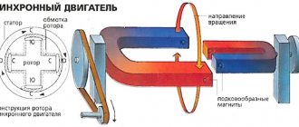
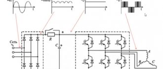
An idea of the appearance and nature of functioning will be complemented by the following figure:
It is clear from it that the stator includes four windings arranged crosswise, that is, at an angle of 90 0 to each other. From here it is clear that discrete movement will be carried out by the same amount of degrees. If the voltage is applied alternately - U1, U2, U3 and so on - the rotor will make a full revolution, and then go to the second circle, that is, it will begin to rotate - until it needs to be stopped. Well, to change the direction of its movement, it is enough to use the turns in the reverse order.
What are stepper motors: let's look at their varieties
The operating modes of the motor determine 2 characteristics: the step size and the force applied to move. You can vary them by changing the connection method, the structure of the windings or shaft.
Accordingly, the classification of drives is carried out according to the following parameters:
- Regarding the design of the rotor, its structure plays a key role, since the specifics of interaction with the electromagnetic field of the stator depend on it. There are 3 options, and we will consider each of them below, with all the features, pros and cons.
- By type (number of windings) - as their number increases, the rotation becomes smoother, but at the same time the cost of the power unit increases, although the torque remains unchanged. They can be uni- and bipolar, in the first case they are connected with a branch from the midpoint, in the second - through 4 outputs.
Now let's pay attention to the structure of the shaft.
Variable reluctance stepper drives
As the name suggests, it does not have its own source of a constant field; In addition, its rotor is made of soft magnetic material and has a toothed shape. Through the contact areas closest to the stator, closure occurs - with attraction to the poles, providing discrete movements. In its design, it is similar to a gear, in which the rotational force appears due to opposing pairs and alternating current flow.
The key advantage is that there is no stopping moment, because the field, which in other cases can influence the reinforcement, is simply absent. You get a synchronous power unit in which the rotor and stator turn simultaneously and in unison.
Having the same dimensions as other varieties, these models develop less torque. The movement is carried out by 5-15 degrees, and this is relatively rough and often inaccurate. This explains the somewhat limited scope of application of a reactive stepper motor: where a motor of this type is used, it is in specific machines, all the parts of which are manufactured by the manufacturer independently.
With permanent magnets
Again, it is immediately clear what their peculiarity is - the presence of their own source of a constant field, which is
the basis of a moving element and containing 2 or more poles. It is the latter that ensure rotation of the rotor by applying voltage to the windings and attraction/repulsion.
The movement can be carried out either completely perpendicular to the previous position, or halfway; By increasing the number of magnetic pairs, you can adjust the length, and therefore the number of discrete movements, bringing their total number to 48 per full revolution. This allows you to very accurately install the working tool in the right place and is a competitive advantage of the power unit.
Hybrid
The design of this type of stepper motor was developed to combine the advantages of the previous two. It is a cylindrical field source, magnetized longitudinally, that is, a pair of poles with special surfaces - with applied teeth. The latter provide excellent retention without reducing torque.
Practical advantages:
- small step - 0.9-50 - which allows precision positioning due to a large number of discrete movements (up to 400 per cycle);
- high speed and smooth operation.
Yes, they are more expensive than the two previous types, since they are more difficult to manufacture, but this is a relative minus. Due to their advantages, these are the most common options today, used in the most critical cases: installed in CNC machines, in modern robotics devices, on medical and office equipment.
Types and design features
Today, several types of motors are used, differing in design, type of windings, control features and other parameters. Let's look at each classification in more detail.
By rotor design
Many engine characteristics regarding rotation speed and operating mode depend on the rotor.
From this position, three types of devices are distinguished.
Reactive (synchronous). A special feature is the absence of a rotor magnet. Structurally, it is made of special alloys that reduce inductive losses. The device looks like a gear with teeth, and voltage is supplied to the stator poles from the second pair. As a result, a magnetic force is created to move the rotor. According to the principle of operation, a reactive stepper unit has much in common with a synchronous motor, where the rotor and stator fields rotate in the same direction.
- Motor with magnets. Unlike the previous device, the moving element is equipped with a permanent magnet with two or more poles. The rotor rotates due to the attraction and repulsion of the poles using an electric field at the moment a potential difference is applied to certain windings.
- Mixed. Hybrid devices combine the best qualities of magnetic and reactive motors. Unlike previous models, the angle and pitch are smaller here. Structurally, the rotor is equipped with a permanent magnet having a cylindrical shape. Externally, it looks like two poles with a round cross-section, on the surface of which there are rotor teeth. This feature guarantees good rotation and holding torque. The main advantages are maximum smoothness, accuracy and speed of movement.
By winding type
The smooth operation of a stepper motor is directly dependent on the number of windings, so it is important to pay special attention to this factor.
Many people mistakenly believe that the number of windings depends on the number of phases. This is not true, because even a 2-phase motor can have four or more windings.
Stepper motors are:
- Unipolar. A special feature is the presence of a tap from the middle point, which allows you to easily change the poles. The disadvantage is that some turns are used, which reduces the torque. To increase power, it is not recommended to connect the middle pin. Structurally, unipolar devices contain five and six terminals.
- Bipolar. This group includes a stepper motor connected to the controller via four taps. The windings can be combined in parallel or in series. To change the direction of the current, so-called chips are used that provide manual control. This effect can be achieved using an H-bridge. Compared to the unipolar type, the bipolar type guarantees the same torque, but at a smaller size.
By type of control
To expand functionality and ease of use, a control system is provided.
It comes in the following types.
Wave: excitation of only one winding. The disadvantage is the minimum available moment.
Full-step: simultaneous activation of the windings.
Half-stepping: cutting the geometry of a stepper motor in half. Provides increased resolution when positioning the unit shaft.
Type
When choosing stepper motors, you need to understand that they come in several types.
Let's briefly look at their features:
- Bipolar motors are two-phase with angular movement of 0.9 or 1.8 degrees. The developers guarantee high step accuracy without load of up to 5%.
- With encoder (often called hybrid servo motors). The special feature is the presence of an incremental encoder. The motors combine the best qualities of servo and stepper electric motors, and the price of such devices is lower compared to a servo system. Used in conjunction with a controller.
- Linear (actuators). The operating principle is based on converting rotational motion into linear motion. In other words, they combine a helical gear and a motor, combined in a common unit.
- Stepper motors with gearbox. They are used in situations where it is necessary to obtain maximum force on the shaft of an electric drive with a minimum rotation speed. The gearbox is a planetary type equipped with spur gears with a slight transmission backlash.
The market offers a large selection of devices that have individual characteristics and are suitable for certain areas of activity. These points must be taken into account when choosing a model.
Closed and open-loop systems
Axis positioning systems allow intelligent controllers to position equipment with exceptional accuracy. A command is issued to move to the desired point in three-dimensional space and the machine responds very quickly and accurately.
Positioning systems typically use one of two methods: closed-loop and open-loop systems. So what is the difference between these two approaches to positioning?
Closed-loop systems typically use servo motors to control the speed and position of a moving axis. Servo motors work just like any regular motor, when power is applied to them they rotate. This rotation takes on a continuous smooth motion. The job of a servo motor is not only to drive the motor, but also to precisely control the speed.
Along with speed, position feedback is also required in a closed-loop system. This is usually provided by an encoder or linear scale. Positional feedback to the machine's controller allows it to move quickly to a target location and then smoothly slow down to settle on the target.
Open loop systems do not have a feedback device to control speed or position. Instead, the distance to be covered from the current location is divided by the machine control system into several precise steps of a certain size. The control system also determines the optimal system speed curve based on predefined parameters. The commands are then sent to the stepper motor in the form of pulses. The job of a stepper motor driver is to convert command pulses into actual motor drive steps, then the stepper motors advance through these steps to achieve the desired result.
↑ Engine (motor)
I chose a stepper motor (SM) as the motor for the drive. Why stepper?
What is this anyway? There are AC and DC motors, brushed and brushless, and so-called “stepping” motors. In any case, we need to ensure some positioning accuracy, for example 0.01 mm. How to do it? If the motor has a direct drive - the motor shaft is connected directly to the propeller, then to ensure such accuracy it is necessary to rotate it through a certain angle. In this case, with a gear pitch of 4 mm and a desired movement accuracy of 0.01 mm, this is... only 1/400 of a revolution, or 360/400 = 0.9 degrees! Nonsense, let’s take an ordinary motor... With a “ordinary” motor without feedback it will not work. Without going into too much detail, the motor control circuit needs to "know" what angle the axle has turned. You can, of course, install a gearbox - we will lose speed, and still there is no guarantee, no feedback at all! A rotation angle sensor is installed on the axle. This solution is reliable, but expensive.
An alternative is a stepper motor (read for yourself how it works). We can assume that in one “command” it will rotate its axis by a certain degree, usually 1.8 or 0.9 degrees (the accuracy is usually no worse than 5%) - just what is needed. The disadvantage of this solution is that under heavy load the engine will skip commands - “steps” and may stop altogether. The issue is resolved by installing a obviously powerful engine. Most amateur machines are made using stepper motors.
What drivers for 3D printer stepper motors can you buy?
1. TMC2208, TMC2130, TMC2100. Output current per winding with additional cooling is up to 2 A, peak output current 2.5 A. Power supply voltage: 4.75 - 36 V. Step crushing: 1/2, 1/4, ⅛ and 1/16 with the possibility of interpolation up to 1/256. It is used to reduce noise when working with 8-bit microcontrollers. It can be used in devices with low-power operating modes, as well as in equipment where high energy efficiency of motors is in demand. The TMC2208 is built on a chip from Trinamic and is capable of delivering up to 2.5 A per winding, which is enough for use in 3D printers and CNC. At the same time, the problem of noisy operation of stepper motors is solved due to effective algorithms for generating control pulses (StealthChop2™) and current control.
Quiet drivers, we recommend installing them. It costs more than the others, about $15.
2. A4988 Permissible output current per winding with additional cooling - up to 2 A, without cooling - up to 1 A. Power supply voltage: 8-35 V. Advantages of the A4988 driver - the presence of protection against overloads and overheating, the ability to adjust the current and several options microstepping. Step crushing: 1, 1/2, 1/4, 1/8, 1/16. 9V is significantly quieter than 12V, without loss of torque. A sharp increase in sound occurs from 11V to 12V. Cost about 6 $.
We recommend reading: What is a capacitor and why is it needed?
4. DRV8825 Permissible output current per winding with additional cooling – up to 2 A. Power supply voltage: 8-45 V. Electrical and mechanical compatibility with the A4988 driver. Step crushing: 1, 1/2, 1/4, 1/8, 1/16, 1/32. According to reviews, they have a design flaw that results in the appearance of defects on the surface of the print in the form of vertical stripes (zebra stripes). The disadvantage can be eliminated by installing TL-Smoother, but it will be much more cost-effective to buy TMC2208 instead. Cost about 6 $.
Experiment No. 2. TMC2208 + ATtiny44
TMC2208 is the name of the driver chip for controlling bipolar stepper motors; the module based on it is also called, which is produced for installation in homemade (and not only) 3D printers and has a unified pinout arrangement.
A lot has been said clearly about this module here. A lot has been written on the Internet about how to install it in your 3D printer, but we are interested in how to connect the module to a microcontroller, so let’s figure it out.
The characteristics of the microcircuit are impressive (only for impressionable people):
- logic part supply voltage: 3-5V;
- motor supply voltage 5.5-36V;
- peak current 2A;
- setting the maximum motor current;
- UART interface support for both control and configuration of internal registers;
- automatic power off;
- support for microstepping motor control up to 1/16th step.
It is very simple to control; in fact, you only need two pins of the microcontroller. We connect one to DIR - we indicate the direction of rotation of the motor, the other we connect to STEP - when a pulse is applied, the microcircuit performs the necessary manipulations with the currents and voltages on the motor windings and it takes one step.
The connection diagram will look like this:
Additionally, I used the EN pin to turn off the motor and not keep the windings energized for a long time.
Source code in WinAVR environment
#define F_CPU 8000000UL // specify the frequency in hertz // fuses must be set L: E2; H:DF; Ex:FF; // this will be a frequency of 8 MHz from the internal oscillator with the clock prescaler turned off (enabled by default and equal to #include // connect the AVR library #include // connect the delay library #include // connect the interrupt library // control the standard LED #define LED_pin PA5 #define LED_ON PORTA |=(1<<<<<
- < <<0) { // haven't done the required number of steps yet STP_ON; // take one step delay_microsecond(100); // pulse duration 100 μS STP_OFF; delay_millisecond(step_delay); // pause between pulses step_quantity—; } } int main (void) { DDRA |=(1<< <
Before you start everything, you need to pre-configure the module. First, set the desired microstep mode. Secondly, set the desired maximum motor current.
With microstepping everything is simple. Pins MS1 and MS2 are responsible for this.
I note that the microcircuit does not change the voltage abruptly, but does it “smoothly”, but since the microcircuit is digital, the output is not a smooth signal, but a signal with a small step; according to the documentation, it breaks each step into 256 microsteps. This was done to increase smoothness, reduce noise from the engine and, in theory, should not allow the structure to which it is screwed to resonate. In short, everything to make the 3D printer work more quietly.
To set the motor current, you need to measure the voltage at the Vref contact, which is shown in the figure. You can change the voltage value using a potentiometer installed next to the contact. The voltage at the contact will be proportional to the motor current, and the relationship will be as follows:
Vref = I*1.44;
Our motor needs approximately 150mA, so Vref = 0.216V
. Installing...
It is understood that the microcircuit provides an increase in current by increasing the voltage on the winding. Therefore, you need to make sure that this voltage is enough. But I think 5V should be enough for that little motor.
Let's test the operation of the motor with different microstepping modes and see what happens (pause between microsteps is 10ms):
You can notice that the movements of the motor have become smoother (compared to the previous experiment), but the characteristic 16 steps are still observed quite clearly.
Well... apparently this is a feature of stepper motors with a rotor made of permanent magnets
. It should also be noted that the motor in this mode heats up almost as much as in full-step mode with two phases. This is understandable, the windings are constantly under voltage, and heat is continuously generated.
I believe that for such motors the use of such a driver, and indeed microstepping modes in general, is not very advisable.
Smoothing device TL-Smoother
A board that connects the stepper driver and stepper motor, reducing noise and vibration in your 3D printer, reducing the risk of zebra stripe defects.
This small board has eight rectifier diodes that improve the stepper motor waveform, particularly for older, cheaper stepper drivers such as the DRV8825 and A4988. Improving the waveform reduces engine noise by reducing vibration. Since vibrations are reduced, print quality also improves. Just install the board between the driver and the stepper motor, the orientation doesn't matter. For convenience, the kit includes a small 4-wire connector, 20 cm long, to connect the board to the electronics. Cost about 7 $
Zebra stripe or moire defect
Connecting stepper motors
The choice of stepper motor connection diagram depends on:
- number of wires in the drive;
- way to start the mechanism.
Existing engine models have 4, 5, 6 or 8 wires. A device with four wires can only be connected to bipolar devices. It is equipped with two phase windings, each of which has two wires. To connect the driver step by step, you need to identify pairs of wires with a continuous connection using a meter.
In a six-wire mechanism, each winding has two wires and a central tap. The engines of this model are characterized by high power and are connected to both bipolar and unipolar actuators.
In the first case, one center tap of each winding and one end of the wire are used.
In the second case, all six wires are used. The separation of the wire is carried out using a measuring device.
The difference between a five-wire motor and a six-wire model is that the center terminal connection is a solid cable that goes to the center wire.
Since separating one winding from another without breaking is not possible, it is necessary to determine the center of the wire, and then connect it to other conductors. This will be the safest and most effective solution. Then the engine is connected to the network and its functionality is checked.
To successfully operate the mechanism, you need to keep in mind the following nuances:
- The rated voltage is produced by the primary winding at constant current.
- The change in initial torque speed is directly proportional to the change in current.
- The rate at which linear torque decreases at subsequent high speeds depends on the inductance of the windings and the drive circuit.
Typical SD connection diagrams
Connection diagram of a 6-pin stepper motor to the GeckoDrive driver (bipolar serial connection of windings)
Connection diagram for an 8-pin stepper motor with bipolar parallel connection of windings to the GeckoDrive driver
Connection diagram for an 8-pin stepper motor with a bipolar serial connection of windings to the GeckoDrive driver
Stepper motor control
There are three stepper motor control modes:
• full step
• half-step
• microstepping.
Full step control mode
The first method was described in the examples above. This is alternating phase switching, the phases do not overlap, at any time only one phase is connected to the voltage source.
The method is called in English one phase on full step - one phase per full step. The rotor balance points coincide with the stator poles. The disadvantage of this mode is that at the same moment half of the windings are used for a bipolar motor, and only a quarter for a unipolar one.
There is a variant of a full-step control mode in which two phases are turned on at the same time. It's called two-phase-on full step - two phases per full step. With this method, the rotor is fixed between the stator poles by supplying power to all windings.
half-step mode
This allows you to increase engine torque by 40%. The pitch angle does not change, the rotor is simply shifted by half a step in equilibrium. This method allows you to get twice as many steps from the engine per rotor revolution.
Every second step one phase is turned on, and between them two phases are turned on at once.
As a result of such commutation, the angular movement of the step is reduced by half, or the number of steps is doubled. It is not possible to obtain full torque in half-step mode.
Despite this, the half-step mode is often used. Using very simple methods, it doubles the number of engine steps.
It must be remembered that for both modes it is true that when the engine is stopped and voltage is removed from all phases, the engine rotor is in a free state and can move due to mechanical influences.
microstepping mode
To fix the position of the rotor, it is necessary to generate a holding current in the motor windings. This current can be significantly less than the rated current.
The ability of the stepper motor to fix its position when stopping allows you to do without mechanical clamps, braking systems, etc.
Control of brushless motors
A controller is required to control a stepper motor. The controller is a circuit that supplies voltage to one of the stator coils. The controller is made on the basis of an integrated circuit of the ULN 2003 type, which includes a set of composite keys. Each switch has protective diodes at the output, which allow you to connect inductive loads without requiring additional protection.
An H-bridge system is used to control brushless motors. Which allows you to switch the polarity to reverse the stepper motor. It can be performed on transistors or microcircuits that create a logical chain for moving keys.
As you can see, voltage is supplied to the bridge from the power source V. When contacts S1 – S4 or S3 – S2 are connected in pairs, current will flow through the motor windings. Which will cause rotation in one direction or another.
With controller
The controller device allows you to control the stepper motor in various modes. The controller is based on an electronic unit that generates groups of signals and their sequence sent to the stator coils.
To prevent the possibility of damage in the event of a short circuit or other emergency situation on the motor itself, each terminal is protected by a diode, which will not allow a pulse to pass in the opposite direction.
DIY ball motor driver
If desired, a driver for a ball motor can be made independently, but subject to the purchase of the necessary equipment. First, decide what type of shield you have in your hands.
There are only two windings in a bipolar device, so the number of outgoing wires will be four. In a unipolar motor there are more windings, therefore the number of leads is corresponding.
The bipolar motor control circuit consists of several elements:
- Pulse generator.
- Switch.
- Power switches that control motor windings.
The generator is assembled on the basis of a 555 microcircuit according to the usual scheme. Each pulse issued by the generator moves the motor one step.
The switch is assembled on the basis of the 4013 chip, and the power part is L239D (driver chip).
Two batteries are used as a power source, providing a voltage of five volts. After turning on the power, the generator emits pulses, the frequency of which can be changed by adjusting the resistance of the generator.
Depending on the circuit used, you can use reverse or connect the motor without it.
To ensure reverse, the same chain is assembled with the difference that at the output of the commutator it will be possible to change the polarity on the windings. In other words, when the connection principle changes, the direction of rotation also changes.
The reverse circuit uses two FAN 8082 brushed motor drivers. After turning on the motor, you can press the switch to rotate in a different direction.
Connection diagrams.
Instead of a generator, you can connect a tact button, with which you can easily avoid chattering of contact groups. If desired, you can even count the number of steps of the motor if necessary.
Features of the first L293D driver (for the first circuit):
- Device voltage is from +5 to +15 V.
- Board size 60x21 mm.
- The maximum current is 1.2 A, but in practice, at a current greater than 0.5 A, the circuit begins to heat up.
- Connected pins - 4, 5, 12, 13.
Features of the second FAN 8082 driver (for the second circuit):
- Device voltage is from +5 to +15 V.
- Maximum current - 1.6 A.
Unlike the previous device, this type of driver copes better with the load. If desired, as noted above, you can use a contact bounce absorber.
DIY stepper motor controller
The task is simple: using the ready-made circuit and program of Pavel Bakhtinov from this forum, lay out a printed circuit board, assemble and debug a controller for controlling stepper motors installed in the mount of an astronomical telescope. Next, you need to make a decent case and control panel. It all starts with the details (Murphy’s law immediately comes to mind: “No talent could survive the passion for details”):
Working on the diagram:
We lay out the printed circuit board:
The photo template is ready:
Here I need to say a few words about my KNOW-HOW in making photo masks for transferring a design onto a printed circuit board.
Usually I print them on a printer - often on an inkjet, less often on a laser, because... The thermal film shrinks unexpectedly after heat treatment in the laser (and templates are needed for both sides), so it was impossible to align the two templates with sufficient accuracy (up to 0.15 mm).
The inkjet printer reproduces the dimensions well, but does not fill the paths with black densely enough; in some places they are still visible. A solution to this problem was soon found: we print not with pure black, but a little lighter towards yellow - the printer begins to add yellow (opaque to UV radiation) and tracks to the black ink, although they look more transparent, after photo transfer they turn out denser, practically without Izyanov.
We recommend reading: Direct electric current power
The main thing is to choose the exposure:
The process of etching the printed circuit board is in progress:
Fully etched:
We drill holes with a diameter of 0.7mm to 1.5mm using a homemade drilling machine:
The soldering iron is old and remote:
We stuff the board with details:
All parts are sealed:
The reverse side of the board, the debugging process has begun:
This is how we will place the heating elements (those above in the figure on this side of the board are an integrated stabilizer and two microcircuits - motor drivers) on such beautiful radiators:
At this time, work has begun on the remote control. The main thing in the control panel, I think, is ergonomics, as far as it is appropriate to apply this to the box that will be obtained after assembly on domestic LARGE but reliable microbuttons.
What are multi-axis controllers
In simple words, multi-axis controllers are modern devices with built-in microprocessors and an integrated programmable circuit.
They are small in size and easy to operate. They are used for precise positioning of units along two or more axes.
The main area of application is the automation of a machine stepper motor equipped with multi-axis electric drives. Their special feature is the support of multiple languages and the ability to manage online.
Controller Features:
- isolated digital inputs/outputs;
- high level of productivity;
- support for slave/master devices;
- option for remote control of the controller;
- interpolation support (circular, linear);
- a large set of digital and analog inputs/outputs, Internet ports and PWM outputs.
Popular models:
- PoKeys57CNC is a CNC controller with eight axes for Mach3 and Mach programs. Its feature is that it supports work via a USB and Ethernet interface. Standard STEP and DIR signals are used for control; up to eight stepper-type drivers are provided. The model is combined with encoders, a hand-held control panel, an LCD display, and limit switches. There are two relay and four transistor outputs, the ability to increase the number of outputs, Modbus TSP support, etc.
- Leadshine SMC6480 is a controller designed for microprocessor-based position control. Its structure includes a logical integrated circuit designed to send pulses, control the acceleration and deceleration process, and process inputs and outputs. The device is capable of reproducing pulses with a frequency of up to 5000 kHz and can withstand interpolation of up to four axes (linear) and up to two axes (circular). Individual analog and digital inputs/outputs, manual input and PWM output are provided.
Leadshine SMC6480 controller
In addition to multi-axis controllers, you can find other devices, for example, plasma heights. They monitor the presence of a working plasma arc and send a command to the main CNC board to move the torch.
SD controllers
Controllers are switching boards used to convert control commands coming from a PC into a sequence of pulses for drivers. The board may have additional functionality - connectors for connecting limit stops, power relays, connectors for spindle control. Connects to a computer via LPT or USB interface.
Multichannel SD drivers are a device that combines SD drivers and a switching board. They connect to a PC and directly control the SD. The controller also includes such functionality as a coolant timer, a PWM converter for the inverter, power relays, connectors for connecting linear movement limitation sensors. Drivers can be executed for different numbers of SDs.
Advantages and disadvantages of a stepper motor
The advantages of using a stepper motor include:
- In stepper motors, the angle of rotation corresponds to the number of electrical signals supplied, while after stopping the rotation, the full torque and fixation are maintained;
- Precise positioning – provides 3 – 5% of the set step, which does not accumulate from step to step;
- Provides high speed start, reverse, stop;
- It is highly reliable due to the absence of rubbing components for current collection, unlike commutator motors;
- The stepper motor does not require feedback to position;
- Can produce low speeds for a directly applied load without any gearboxes;
- Relatively lower cost compared to the same servos;
- A wide range of shaft speed control is provided by changing the frequency of electrical pulses.
The disadvantages of using a stepper motor include:
- A resonance effect and slippage of the stepper unit may occur;
- There is a possibility of loss of control due to lack of feedback;
- The amount of electricity consumed does not depend on the presence or absence of a load;
- Difficulty in control due to the design of the circuit
Add a link to a discussion of the article on the forum
RadioKot >Schemes >Digital devices >Protection and control >
| Article tags: | Add a tag |
4 Axis Step/Dir Stepper Motor Controller
Author: Roman Lut Published 09/06/2013 Created with the help of KotoEd. Participant of the Competition “Congratulate the Cat as a Human Being 2013!”
The article describes the step/dir controller of unipolar stepper motors.
The controller is used to control a homemade drilling and milling machine .
It is assumed that the reader is already familiar with homemade CNC machines; otherwise, it is recommended to study the materials indicated at the end of the article. Introduction
The controller was developed to replace the existing primitive 3-axis controller (ATTiny2313). The main requirements were support for microstepping and hardware control of current in the windings in order to reduce noise and increase movement speed.
Controller characteristics:
— 4 axes; — for unipolar motors; — hardware control of current in the windings (PWM); — optical isolation with LPT port; — holding mode with current reduction to the specified value; — full step, half step, 4, 8, 16 microstep is selected separately for each axis; — maximum pulse repetition frequency step: 12.5 kHz (period — 80 μs); — minimum step and dir pulse length: 5 μs; — motor current — up to 2A, individually for each axis (more than 2A was not tested, the circuit allows); — motor power supply — up to 30V, with the possibility of increasing (more than 19V has not been tested).
In general, the result is a fairly “sophisticated” controller using cheap, common components. None of the homemade controllers known to me has such a set of capabilities.
Control module
The control module is made on an ATMega8535 operating at a frequency of 16 MHz. The controller's job is to process the Step/Dir and provide turn-on signals and reference voltages for the power part of the circuit.
The reference voltages are generated by the M62359 - this is an 8-bit 8-channel DAC with an SPI interface. PC817 optocouplers and is an integral part of the controller. At this point we need to dwell separately.
As can be seen from the diagram, unlike similar controllers, Step are not connected to the microcontroller pins, which cause hardware interrupts. Instead, the controller spins in an endless loop, checking to see if the logic levels at the inputs have changed. This ensures stable, predictable operation of the controller.
One cycle (checking inputs, reacting, outputting control signals) takes ~26 µs . Step pulse length is 5 μs . How does the controller not miss pulses?
This, so to speak, is my know-how. The secret is in the properties of optocouplers.
In the PC817 you can find Response time . After the signal at the input disappears, the optocoupler requires a certain time (ts + tf) to close. This time depends on the current that flows through the phototransistor.
In practice it looks like this: Input pulses - 5 µs , period - 80 µs :
Load resistor 10kOhm at 5V - and the input pulse of 5μs turns into ~28μs the AVR input can be confidently read as “0” is 0.8Vcc = 1V ):
Thus, the microcontroller has at least 28 µs to poll the inputs. As a result, he alone can control 4 axes at once.
Power section
The four power boards are completely identical and are assembled using UC3842 IRFZ44 or IRF560 transistors (the transistors are located on the reverse side of the board):
The current in each winding is controlled by a separate microcircuit and transistor:
UC3842 chip is a PWM controller for switching power supplies. It contains a PWM generator, a current comparator, an RS trigger and a field effect transistor driver. In general, it is ideal for these purposes
Initially I tried to build a controller using TL494 . But, as it turned out, these microcircuits are not designed to control the maximum current during one PWM period. Their input current and voltage sensors should be cut off with filters with a frequency of 10-15 kHz.
The UC3842 , on the other hand, is designed to limit the maximum current through a transformer winding during one period. It turns off the transistor when the set current is reached:
The reference voltage generated by the DAC on the control module is supplied to the Comp of the microcircuit. At the beginning of the PWM period, the microcircuit opens the transistor. The current in the winding begins to increase smoothly. As soon as the current exceeds a predetermined value, the microcircuit turns off the transistor.
The UC3842 measures winding current by the voltage drop across the current sense resistor. In addition to comparison with the reference voltage, the microcircuit provides overcurrent protection, which turns off the transistor when the voltage across Isense is higher than 1V. Therefore, the current-measuring resistor must be selected in such a way that at maximum current the voltage drop across it is slightly less than 1V. The exact value of the maximum current is set in the firmware. The board has places for resistors R9-R11 , which allow you to dial the required resistance.
The microcircuit contains a built-in oscillator, the frequency of which is set by the R3C2 :
During the discharge of the capacitor, the output transistor turns off (this is dead time ). Thus, by choosing the R3C2 you can set both the frequency and dead time . Naturally, these elements must be the same for all windings.
The PWM frequency is selected individually for the motor, taking into account the increase in motor heating with increasing frequency.
To avoid installing additional components, you can use the Clock , which is generated by the microcontroller. The frequency and dead time are set in the firmware. Elements R3C2 are not installed - resistor R4 .
One DAC output provides a reference voltage for a pair of windings (only one of which can be turned on at a time). Therefore, the control module turns off (at a high logical level) the paired winding with the /M_L1EN .
R1C1 chain is selected in such a way as to extinguish the current surge that occurs when the transistor opens:
Diode D1 is installed optionally. The built-in MOSFETs were enough for me.
When the transistors are turned off, back EMF surges occur, and voltage surges on the Drain-Source transistors can exceed the supply voltage by 3 times. Power supply - 19V, DSHI-200 :
Classically, these emissions are suppressed by shunt diodes installed on the windings or diverted to the power source. However, it must be taken into account that the shunted winding slows down the motor and does not allow high rotation speeds to be achieved. Therefore, emissions need to be extinguished only when the limit value is exceeded, which is ensured by turning on a zener diode opposite the diode:
It is advisable to simply choose transistors with a sufficiently large Vdss . I used IRF540N (Vdss = 100V) for the DSHI-200 and IRFZ44N (Vdss = 55V) for printer motors.
Let me remind you that Vdss is the voltage between Drain and Source , at which the transistor spontaneously opens. In practice, this causes incorrect operation of the controller, heating of the transistors at relatively low currents through them, or failure of the transistors. For motors up to 3A, the mosfets must be cold; radiators are not installed on them.
Nutrition
The controller is powered from a 19V 3A laptop power supply:
5V are obtained using a ready-made DC-DC converter module on LM2596 , available on ebay:
Why is current control important?
In a stable state, the current in the winding is determined only by the active resistance of the winding and the supply voltage. But at the moment of switching on, the current in the winding depends on both active and reactance. Therefore, instead of rectangular current pulses, we will see the following picture:
The greater the inductance of the winding, the longer the rise and fall of the current will occur. When the rotation speed increases, the current will not have time to increase to the maximum value, and the motor torque will begin to fall:
To ensure a rapid increase in current, you need to increase the supply voltage. But in a stable state, the current in the winding is limited only by the active resistance of the winding. Therefore, limiting the current when the supply voltage increases is mandatory.
Another way to increase speed should be mentioned. The motor supply voltage is increased, and the motor itself is turned on through a powerful resistance. By this we reduce the proportion of reactance in the winding circuit. This effectively solves two problems at once: increasing engine speed and heating the workshop.
Engine operating modes
The engine operating mode is indicated in the firmware individually for each axis.
Full Step, Full phase (full step, one winding)
Classic mode, in which one winding is turned on at a time.
Full Step, Half phase (full step, two windings)
A mode in which at any moment 2 adjacent windings are turned on simultaneously. This inclusion can increase the engine torque (easily implemented, but not used in the current firmware).
Half step
A combination of previous modes. The number of steps doubles. When two windings are turned on, the current in each is set to 0.707 * Imax .
Microstep 4, 8, 16
If you imagine how the motor rotates in full step mode, you will notice that it moves jerkily: first it accelerates, attracted by the next winding, then it slows down, reaching its final position. This causes vibrations in the shaft and the entire machine as a whole.
This is how the machine works, during the creation of which the issue of noise reduction was not considered:
Everything is bad here - powerful motors in full step mode, a huge resonating chipboard body... Just like in my first machine, which had to be disassembled due to noise. In a residential area, the issue of noise reduction is not a whim, it is a question of whether it will be possible use the machine at all.
To ensure smooth rotation of the motor, it is necessary to power the motor with sinusoidal current. To do this, in stepper motor controllers the moment of transition from one winding to another is divided into 4-16 microsteps. At each microstep, the current in the first winding decreases, and in the second it increases, according to a sinusoidal law:
In this case, the frequency of Step in the control program should be increased by 4-16 times, respectively.
Using microstepping can significantly reduce engine noise and produce higher torque at high speeds. The machine begins to “sound professional”:
I personally don't consider microstepping as a way to improve positioning accuracy because the design of the rotor and stator does not guarantee an even distribution of microsteps. In addition, with a slight force, or when switching to hold mode, the motor shaft may “fall out” into the full step position.
Hold mode
Step pulses for ~2 seconds , the controller reduces the current in the windings to the values specified individually for each axis in the firmware.
Comparison with modules on Allegro chips
The popularity of homemade 3D printers has caused the appearance on ebay of ready-made modules based on A4983 , which are quite difficult to compete with “in bulk”. On the other hand, it was calmer for me to experiment with a circuit where, in the worst case, I would have to replace the keys, than with a 3x3mm microcircuit, which would explode if there was any mistake.
In addition, in the future it is planned to expand the controller for autonomous operation from a small remote control, since creating a program every time you need to make an even cut is inconvenient. And in the very distant future, it may be possible to implement control via USB (this is when the controller receives a description of the steps from the USB-UART and generates the steps itself).
The described controller is equivalent to 4 such modules + an optocoupler board.
Differences: - in Allegro , current surges when the bridge transistors are turned on are ignored for a fixed time interval - 1us. Here the emissions are suppressed by the R1C1 ; — Allegro can turn on the “fast current reduction mode.” If at the next microstep the current in the winding should decrease, the chip briefly bypasses the winding, opening the bridge transistors. Introducing such a feature into this (unipolar) controller would add too much complexity to the circuit; — for A4983, Step pulses is 1/2 μs = 500 kHz.
I tried connecting the same motor to this controller in a unipolar connection and to the A4983 in a bipolar connection. Subjectively, the unipolar connection gave more torque at high speeds. Perhaps due to the lower winding inductance when switched unipolarly.
Printed circuit boards
Firmware, fuses
The firmware is written in C for CodevisionAVR 2.05. If desired, the main loop can be rewritten in assembler and increase the maximum Step to ~20 kHz .
When programming the microcontroller, you need to turn off the power from the power unit.
Mach 3 setup
Ideally, the control program should be able to generate Step exactly at the required frequency. In practice, in the Mach3 and similar programs, the driver operates at a fixed frequency (Kernel speed) :
Therefore, Mach3 can generate pulses only at the boundaries of Kernel speed . For example, if it is necessary to generate pulses with a frequency of 16 kHz (period - 62.5 µs ) at a core frequency of 25 kHz (period - 40 µs ), then the pulses will follow unevenly - with periods that are multiples of 40 µs :
From the oscillogram at the output of the optocoupler it is clear that the recovery time for confident reading of “1” by the microcontroller is approximately 50 μs . After this, you need to withstand “one” one cycle of the program (26 µs) , for a total of ~76 µs . Therefore, at a core frequency of 25 kHz , the maximum frequency of Step should not exceed 12500 kHz , so that there are at least two periods of 40 μs between pulses:
To do this, the following condition must be met:
Steps per * Velocity / 60 < 12500
Step pulses is set to positive:
Oscillograms
Current sense resistor voltage, low and medium speed (Microstep 8x) :
(should be close to abs(sin(x)) ).
Current sense resistor voltage, high speed:
Repetition of design/disadvantages/improvements
Communication with the M62359 occurs at a frequency higher than stated in the datasheet, so it is advisable to replace it with something faster. In practice, I did not observe any problems with the controller. I manage to successfully mill printed circuit boards, the processing of which includes shading the entire board in 0.3mm increments :
The power circuit boards were installed “for all occasions.” It may make sense to remove seats for optional parts and reduce dimensions. Or make the entire controller on one large board in the SMD version.
It was planned to insert the power boards vertically into the control module, like into a computer motherboard, but in the end it was done on cables. Because of this, the cables had to be clamped with a shift. If I had done it initially, I would have routed it to ready-made cables from drives.
The controller has not been tested with currents greater than 2A - perhaps more attention should be paid to the wiring.
The motor supply voltage can be raised up to 60V. In this case, you need to install the transistors in a large Vdss and select the resistance R8 UC3842 power circuit (the microcircuit contains an internal 30V zener diode). The supply voltage cannot be raised indefinitely, because you can get a breakdown in the motor windings.
Also note the (non-standard) programmer connector.
I would like to warn you right away that to configure the controller you definitely need an oscilloscope. Without it, it will be impossible to understand what is happening in the windings.
Materials
UC3842 CURRENT MODE PWM CONTROLLER https://www.ti.com/lit/ds/symlink/uc3842.pdf
DMOS Microstepping Driver with Translator A4983 https://www.allegromicro.com/~/media/Files/Datasheets/A4983-Datasheet.ashx
Acceleration of stepper motors https://vri-cnc.ru/modules.php?name=News&file=article&sid=22
Acceleration of stepper motors 2 https://vri-cnc.ru/modules.php?name=News&file=article&sid=4&mode=&order=0&thold=0
Losing steps in Mach3: Kernel Speed, Pulse Width and “Sherline 1/2 Pulse mode” https://ivan.blogs.chimerical.com.au/post/2010/07/07/Losing-steps-in-Mach3-Kernel -Speed-Pulse-Width-and-Sherline-12-Pulse-mode.aspx
Electronics and mechanics of a home 3-axis CNC machine (Hobby CNC). https://radiokot.ru/lab/hardwork/33/
hCNC3+ (ATMega16, StepDir, 3 axis, PWM, manual control). https://vri-cnc.ru/modules.php?name=Forums&file=viewtopic&t=1438&start=0&postdays=0&postorder=asc&highlight=
Simple bipolar driver on Pic https://cncmasterkit.ru/viewtopic.php?f=3&t=1393
Microstepping stepper motor controller based on PIC18F2320 V4.1 https://robozone.su/cnc-home/50-mikroshagovyjj-kontroller-shagovogo-dvigatelja-na.html
STEP/DIR controller of 3 stepper motors on a microcontroller (for a CNC machine) https://radiokot.ru/circuit/digital/automat/25/
3 axis STEP-DIR controller https://www.deep-shadows.com/hax/wordpress/?page_id=455
Files:
Scheme, signets (Proteus) Source codes (Codevision AVR 2.05)
All questions in the Forum.
| What do you think of this article? | Did this device work for you? | |
| 49 | 0 | 0 |
| 0 | 0 |
How to connect a stepper motor without a controller
Stepper motors are found in cars, printers, computers, washing machines, electric shavers and many other everyday devices. However, many radio amateurs still do not know how to make such a motor work and what it actually is. So let's learn how to use a stepper motor. Stepper motors are part of a class of motors known as brushless motors. The stepper motor windings are part of the stator. The rotor contains a permanent magnet or, for cases with variable magnetic resistance, a gear block made of soft magnetic material. All switching is carried out by external circuits. Typically, the motor-controller system is designed so that it is possible to move the rotor to any fixed position, that is, the system is controlled by position. The cyclical positioning of the rotor depends on its geometry.
How does a hybrid engine work?
The workings of a hybrid stepper motor can be easily understood by looking at a very simple model that produces 12 steps per revolution.
The rotor of this machine consists of two parts, each of which has three teeth. Between the two parts there is a permanent magnet, magnetized in the direction of the rotor axis, thus creating a south pole on one part of the part, and a north pole on the other. The stator consists of a tube having four teeth inside it. The stator windings are wound around each such tooth.
When current flows through one of the windings, the rotor takes one of the positions shown in the figures. This is due to the fact that the permanent magnet of the rotor tries to minimize the magnetic resistance of the winding. The torque that tends to hold the rotor in these positions is usually small and is called “torque relaxation.” Below is a 12 step motor diagram.
If current flows through the two stator windings, the resulting poles will attract the teeth of reverse polarity at each end of the rotor. There are three stable positions for the rotor, the same as the number of teeth on the rotor. The torque required to move the rotor from its stable position into rotating motion is called "torque hold"
By changing the current of the first to the second winding (B), the magnetic field of the stator rotates 90 degrees and attracts a new pair of rotor poles. As a result, the rotor rotates 30 degrees, which corresponds to a full pitch. Returning to the first set of stator windings, but with reverse polarity supply, changes the stator magnetic field by another 90 degrees, and the rotor turns 30 degrees (C).
Finally, the second set of windings works in the opposite direction, providing a third rotor position (another 30 degrees). Now we can return again to the first stage (A), and after going through all these four stages again, the rotor will be moved one more tooth.
Obviously, if the polarity of the power supply to the windings is opposite to that described, then the rotation of the motor will also change to the opposite.