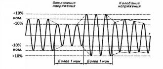
General concepts and scope
A synchronous electric motor is understood as a mechanism whose rotor rotation frequency coincides with the stator rotation frequency, which is started by electric current from the network. In simple terms, the rotor and stator rotate simultaneously, which is why the engine got its name.
Synchronous units operate in engine and generator modes. Therefore, they are sometimes called synchronous generators. Such devices usually use different power plants that generate the majority of the electricity. The productivity of the devices ranges from 1,000 megawatts and more.
Typically, synchronous motors are used where increased power is required to run compressors, pumps, mills and other units where adjustments to repeat circulation and constant starts and stops are not required.
The main specific features of the mechanism that simultaneously rotates the rotor and stator are:
- Continuous agility of the shaft under any traction;
- Possibility of adjusting performance indicators when changing the excitation current.
When overexcited, the unit turns into a compensator, improving the overall cosine F of the network.
Operating modes
The device provides three operating modes: automatic, manual and emergency. It is possible to change modes while the engine is running. The transition from one to another is not accompanied by current surges. Below we will see how the device works.
Auto mode
The specified parameters are maintained using the excitation coordination unit - ARV. Parameters are set using buttons on the remote control or remotely.
ARV supports the specified parameters:
- Mains voltage.
- Motor power factor (cosⱷ).
- Stable operation of the engine when the load increases above the maximum.
- Regulates the stator voltage when the load decreases below the rated load.
Manual control mode
The device allows you to change parameters manually, set by the operator from the engineering console.
In this case, the block provides:
- Direct starting with automatic excitation of synchronous motor coils as a function of stator current and slip.
- Reactor launch. In automatic mode, the stator current is regulated.
- Stabilization of excitation current during sudden load changes.
- Maintaining stabilization current within 5% when the supply voltage changes by 70-110% of the nominal value. When the temperature conditions of the windings change.
- Possibility of smooth current adjustment. If necessary, which can be quickly adjusted.
- Rotor protection from long-term overloads.
- Rapid damping of the rotor field during a long voltage dip. In this case, an extinguishing signal must be given.
- Increase in voltage by 1.75 from the nominal. At normal voltage of the network supplying the exciter.
- Voltage limitation to minimum values.
- Current limitation based on maximum values.
Emergency mode
Designed for engine operation in emergency mode. The analog exciter adjusts the currents from zero to the boost value. There is adjustment within specified limits.
It contains a module that protects circuits when:
- Short circuit of the electronic converter circuits.
- Switching off the excitation of a running electric motor.
- Long asynchronous movement.
- Occurrence of insulation breakdown to ground.
- Overloads exceeding specified values.
- Repeated engine starts.
- Failure of a group of contacts in the switch module.
- Reduced stator voltage.
- Changing the direction of power.
- Increased voltage in the excitation windings.
- When the starting resistor overheats.
Electronic exciters are designed to supply voltage to the excitation winding circuit and regulate excitation currents in automatic mode. Used for high power synchronous electric motors.
Device and essence
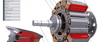
The basis of the unit, like any similar engine, is the stator and rotor. It is worth familiarizing yourself with these components.
The stator is understood as the immovable part of the mechanism, consisting of a base and a core assembled from thin and insulated sheets. The last part has grooves for laying three-phase windings.
The design of stators can be different - cylindrical or segmented. Frames also come in different types - solid or split. The latter are convenient for transportation, repair and installation.
The rotor is the rotating part of the unit. A core with an exciting winding or magnets is installed on it. Both of these elements can be prefabricated or solid.
The rotor is divided into:
- Non-salient pole, which is a steel cylinder with slots with longitudinal perforations intended for the excitation winding.
- Salient pole - the component is equipped with a core at the poles protruding above the plane of the rotor.
Synchronous machines use a specific type of rotor, which is affected by power and number of revolutions. In silent mechanisms, a rotor with a salient-pole arrangement is used, and in devices with a high torsion frequency, a non-salient-pole one is installed, which depends on the influence of centrifugal forces.
The ends of the electrical winding are brought out to the rings, which receive current through the brushes.
Synchronous motor device
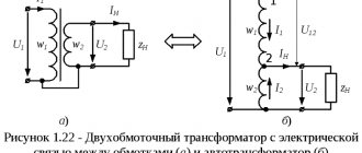
A synchronous motor consists of main parts - an armature and an inductor. Typically, its design is made in such a way that the armature is located on the stator, and the inductor is located on the rotor, separated by an air gap. These units have a high power factor. A significant advantage is the ability to use them in networks with any voltage.
The design of a synchronous motor consists of two main parts - the stator and the rotor. The stator is the stationary part of the unit, and the rotor is the movable part. The armature consists of one or more alternating current windings. When the motor is running, the currents entering the armature lead to rotation of the magnetic field, which intersects with the field of the inductor and converts energy. The anchor field has another name - the anchor reaction field. In a generator, such a field is created using an inductor.
The inductor contains DC electromagnets called poles. In all synchronous electric motors, inductors come in two designs - salient-pole and non-salient-pole, differing in the arrangement of the poles. The stator design includes a housing and a core, which includes two- and three-phase windings. The windings themselves can be distributed or concentrated.
To reduce magnetic resistance and improve the passage of magnetic flux, ferromagnetic cores are used, located in the rotor and stator, for the manufacture of which electrical steel is used. It has interesting properties, such as increased silicon content, in order to increase its electrical resistance and reduce eddy currents.
Each synchronous electric motor has an important parameter - electromagnetic torque. It occurs when the magnetic flux of the rotor begins to interact with the rotating magnetic field. This field is formed under the influence of three-phase current flowing through the armature winding.
Excitation methods
The operation of a rotary synchronous engine depends on the activation of a source of magnetomotive force. This could be a generator in which a magnetic field meshes with the stator windings and imparts an electric force to them. The motor interacts with the magnetic fields of its constituent elements.
There are two methods of excitation - electromagnetic or with a winding, and with permanent magnets. The first ones are quite widespread. In this scheme, when direct current passes through the winding, a moving magnetic force appears, driving a magnetic field in the mechanism system.
In the recent past, stimulation of synchronous units was carried out by direct current generators with a self-excitation circuit or with an independent type of excitation. In the latter option, current is supplied to the exciting winding. An additional AC compensator operating in parallel was used.
Self-excitation, characteristic of synchronous engines and hydrogenerators, is understood as the process of converting direct current energy, which is necessary for stimulation, into direct current. This happens through a step-down transformer and a special converter.
In generators with self-exciting properties, the winding of the poles is powered by electricity generated by the device itself. That is, there is no need to organize a separate energy source. The following types of self-excitation are distinguished, depending on the winding switching algorithm:
- Parallel - the armature current of the device is distributed between the load current and the excitation current. The latter is usually small, and then the generator does not experience high loads. Typically, these units are used as power supplies on cars, ships or aircraft.
- Consistent. The stator winding and the exciter winding are connected to each other in a series circuit. Such devices are rarely used.
- Mixed. These units have excitation windings that have concordant and counter-connected excitation windings. The voltage remains the same as the traction increases or decreases. The devices are used when sufficient stability of the power supply is required when the load changes.
In the modern world, in synchronous motors, tristor devices are responsible for excitation, which are connected to the alternating current network and automatically controlled by the exciting current in different operating modes of the installation. This is the most reliable method, because they have high efficiency. Factories usually produce tristors for various voltages with a possible DC current of 320 amperes.
Low-power “synchronous machines” use a permanent magnet excitation circuit. In this case, there are permanent magnets on the inductor, which makes it possible not to use an exciting winding. As a result, the car frame becomes simpler, more reliable and more economical. But due to a shortage of materials, it is necessary to use devices whose power barely reaches several kilowatts.
Excitation of synchronous machines
Synchronous machines can be excited by electromagnetic action or a permanent magnet. In the case of electromagnetic excitation, a special direct current generator is used, which powers the winding; due to its main function, this device is called an exciter. It is worth noting that the excitation system is also divided into two types according to the method of influence - direct and indirect. The direct excitation method implies that the shaft of the synchronous machine is directly mechanically connected to the exciter rotor. The indirect method assumes that in order to make the rotor rotate, another motor is used, for example an asynchronous electric machine.
The most widely used method today is the direct method of excitation. However, in cases where the excitation system is supposed to operate with powerful synchronous electric machines, independent excitation generators are used, the windings of which are supplied with current from another direct current source, called a subexciter. Despite its bulkiness, this system allows for greater stability in operation, as well as finer-tuning of characteristics.
Self-excitation conditions
Auto-excitation of a synchronous motor with parallel field windings can occur if:
- There is a residual magnetic flux of the poles.
- Correct connection of the ends of the exciter winding or the correct direction of rotation.
For automatic stimulation to occur, it is enough that the residual flow is 2-3% of the nominal one. An atavistic stream with such indicators is always present in an already activated mechanism. But if magnetization has stopped, then you need to pass current from an external source through the excitation winding.
When the necessary rules have already been met, a small EMF, which is induced in the stator by a flow of magnetic particles, causes a small current to appear in the exciting winding, causing an increase in the movement of the poles. This process continues until the electrical power of the generator reaches a certain value.
To achieve normal functioning of electrical appliances, it is necessary to have a stable electrical voltage at the compensator terminals, which does not depend on changes in the overall traction. This can be solved by adjusting the settings.
Rheostats may well close the winding, but if this does not happen, then the electromotive force of self-induction increases, which may well damage the insulating material. During a short circuit, the energy spreads as heat, and then the generator is not destroyed.
Here it is not worth using external power, since the electromagnet contained in the core self-excites the parallel windings. To increase the residual magnetism in the exciter coils, the cores are made of cast steel.
In the process of sequential self-excitation, a current is generated that does not differ from the power of the directed particles of the generator. At idle, the load is zero and there is no excitation. It is impossible to remove or adjust these parameters.
To start stimulation, you need to connect an external load source to the clamps of the device. This is precisely the drawback of the series-connected windings. This is only used for devices that have a constant load.
With mixed self-excitation, the voltage vibration at the designated traction force is softened. This is the main advantage of such devices, but the design is quite complex, and as a result, a bit expensive. Engines of this type cannot tolerate short circuits.
Contents Previous § NextChapter forty EXCITATION SYSTEMS OF SYNCHRONOUS MACHINES
§ 40-1. The problem of regulating the excitation of synchronous machines and requirements for excitation systems
The excitation system of a synchronous machine is a set of machines, devices and devices designed to power its excitation winding with direct current if l
regulation of the magnitude of this current.
The following basic requirements are imposed on excitation systems: 1) high operational reliability and 2) maximum simplicity and low cost. In addition, the need to regulate voltage and ensure stable operation of synchronous machines imposes a number of additional requirements on excitation systems.
To maintain a constant voltage U
at the generator terminals when the load changes, it is necessary to adjust
if
and
, accordingly, within wide limits.
According to GOST 533-68, the minimum stable value of the excitation voltage of
a turbogenerator should be no more than 0.2
UfH.
In exciters in the form of generators, parallel excitation, this is achieved <: using saturation bridges in the magnetic circuit (see § 9-4).
The problem of automatic excitation control.
Powerful synchronous generators, and in many cases also low-power generators, are equipped with automatic excitation current regulators, the purpose of which is: 1) maintaining a constant voltage U
when the load changes and 2) increasing the static and dynamic stability of the generator. The second task is especially important for high-power generators, and at the same time, increased demands are placed on excitation systems and controllers.
With slow changes U
to maintain
U - Un -
const, it is enough to carry out the so-called proportional regulation, when the excitation or voltage regulator responds to a change in
U,
i.e., to the value
AU
=
U
-
Un,
and, depending on the value and sign
of AU,
affects the organ , changing the value of if accordingly
.
For example, for low-power generators, carbon voltage regulators are used, which consist of a column of carbon or graphite disks, a spring that compresses this column, and an electromagnet.
A carbon column replaces excitation rheostat 6
in the circuits of Fig. 34-1, and the electromagnet coil
connects to the generator terminals. As U
the electromagnet weakens the pressure of the spring, the compression force of the column decreases, its resistance as a result increases and
decreases
.
When U
the action occurs in the reverse order
However, with rapid changes in U,
as is the case during transient processes, and to increase stability, such regulation is ineffective due to the mechanical inertia of such a regulator, which has moving parts, and the electromagnetic inertia of the excitation circuit, which has a high inductance.
Due to such inertia, if
will change with a delay and will not keep up with the change in
U,
as a result of which it is impossible to maintain the condition
11 =
= const with the required accuracy.
To avoid this, for powerful generators, firstly, static electromagnetic regulators are used, consisting of elements (electronic amplifiers, etc.) that do not have moving parts. Secondly, to overcome the influence of electromagnetic inertia of the excitation circuit, it is necessary that the action of the regulator be proportional not only U,
but also the rate of change of
U,
i.e.
dU/dt.
If, for example, the voltage
U
begins to drop sharply and quickly and therefore the absolute value of
dU/dt
is large, then the regulator immediately, when At/ has not yet reached a noticeable value, gives a strong impulse to increase
if.
It is also desirable that the excitation pefylator respond to the derivatives of other quantities characterizing the operating mode of the synchronous generator.
For example, as follows from what is stated in § 39-3, to increase dynamic stability, it is desirable that if
be greater, the faster the load angle b increases, i.e., the greater
b' - dQ/dt,
and vice versa.
Since measuring the value of 6 is difficult, instead of 8′ you can also adjust the derivative of the stator current / by the value, since changes in 6 and / during swings occur in a similar way (see Fig. 39-3). It is also advisable to adjust if
in proportion to the second derivatives of certain quantities.
I Regulators that respond not only to the deviations of certain parameters, but also to the values of their derivatives in time, are called strong-action regulators.
Such regulators for synchronous generators were first developed in the USSR for the Volzhskaya HPP named after. V.I. Lenin and have proven themselves in the best possible way.
It should be noted that for such regulators to operate effectively, it is necessary that the electromagnetic inertia of the excitation system be sufficiently small.
It is also advisable to equip synchronous motors with automatic excitation regulators. Their action during voltage drops helps maintain a constant network voltage and increases the stability of the engines.
Upper limit (ceiling) of excitation voltage. During short circuits in the network, the voltage at the generator terminals U
the revco drops, the power they develop therefore also decreases sharply, and since the power of the turbines remains unchanged, there is a danger that the generators will fall out of synchronism.
In these cases, to maintain U
at the highest possible level and to prevent the generators from falling out of synchronism, the so-called excitation boost is applied, i.e. the excitation voltage
Uf
rises as quickly as possible to the maximum possible value
Ufm.
In excitation circuits like Fig. 34-1 this is achieved by the fact that a special relay, which responds to a sharp decrease in voltage, bypasses the excitation rheostat 5 with its contacts.
For excitation forcing to be effective, the upper limit (ceiling) of the excitation voltage is
should be big enough. According to GOST 533-68 and GOST 5616-63, it is required that turbogenerators
Rate of rise of excitation voltage. When excitation is forced, the voltage
should increase as quickly as possible.
According to GOST 533-68 and GOST 5616-63, for turbogenerators the rate of increase in excitation voltage when it is forced must be at least 2Ufa
per second, and for hydrogen generators - at least 1.5 "un per second.
§ 40-2. Excitation systems
Excitation systems with direct current generators. The classic excitation system for synchronous machines, widely used today, consists of an exciter in the form of a parallel excitation generator on a common shaft with a synchronous machine (see Fig. 34-1). For low-speed vehicles with power up to Ra
yay 5000
ket
to reduce the weight and cost of the exciters, the latter are sometimes connected to the shaft of a synchronous machine using a V-belt drive.
Hydrogen generators also usually have an exciter on the same shaft as the generator. However, for powerful low-speed generators with in = 60 -J- 150 rpm
The size and cost of the exciter due to its significant power and quiet speed are large.
In addition, low-speed exciters, due to their large size, have high electromagnetic inertia, which reduces the efficiency of automatic control and excitation boost. Therefore, excitation systems are also used in the form of a separate high-speed unit (n =
750 - 1500
rpm),
consisting of an asynchronous motor and a direct current generator.
In this case, the asynchronous motor receives power from a special auxiliary synchronous generator located on the same shaft as the main hydraulic generator, and in some cases - from the auxiliary tires of the hydraulic station or from the terminals of the main hydraulic generator. In the latter case, the exciting unit is subject to the influence of accidents in the power system (short circuits, etc.), and therefore, to increase its reliability, drive asynchronous motors are made with an increased maximum torque (Mt
:> 4 Mn), and sometimes these units are also equipped with flywheels. Backup excitation units for power plants are also available as separate exciter units, which serve to back up their own exciter generators in the event of accidents and malfunctions.
Turbogenerators with capacity up to Ry
= 100 thousand
kW
also usually have exciters in the form of direct current generators on their shaft.
However, at Рн > > 100 thousand kW
, the power of the exciters becomes so great that their implementation at
pp
= 3000 - t - 3600
rpm
under the conditions of switching reliability becomes difficult or even impossible.
In this case, different solutions are used. rpm,
connected to the turbogenerator shaft using a gearbox, as well as exciter units with asynchronous motors receiving power from the station buses or from the generator terminals are widely used abroad
Some types of excitation systems with DC machines are also used. For example, powerful exciters of large machines sometimes have subexciters (Figure 40-1), which serve to excite the exciter.
In this case, the excitation system is regulated in the excitation circuit of the subexciter, in which a small current flows. This achieves a reduction in the power and weight of control and regulation equipment
Compounded excitation system with a constant current exciter (Figure 40-2) In modern excitation systems, the principle of compounding is widely used, i.e. automatic change in excitation when the load current of a synchronous generator changes, just as it happens in direct current generators with mixed excitation when consistent connection of the series field winding (see § 9-6) Since alternating current flows in the armature winding of a synchronous machine, and in the field winding 2
- direct current, then
semiconductor
rectifiers are used in compounding circuits for synchronous machines. In the schematic diagram of a compounded excitation system with a direct current exciter shown in Fig. 40-2, the exciter winding
4
is connected to the exciter armature 3 with a rheostat
6
and, in addition, to rectifiers
9 ,
receiving power from series transformers
7.
Fig. 40 1 Excitation system with DC exciter and subexciter
/ - armature of a synchronous generator, 2
— synchronous generator excitation winding,
3
— exciter armature,
4
— exciter excitation winding, 5 — subexciter armature,
6
— subexciter excitation winding
Figure 40-2 Current Compounding Excitation System
Generator no-load winding 4
receives power only from armature 3 As the load current of the generator increases / the voltage of the secondary winding of transformer
7
will increase, and even at a small load this voltage, rectified by rectifier
9,
will be equal to the voltage of winding
4
With a further increase in the load, winding
4
will be fed from the transformer
7
and therefore the current of this winding and the excitation current of the generator
c
will increase with increasing load
With increasing resistance of the installation rheostat S
the voltage supplied to the rectifiers
9
and the compounding effect of the transformer 7 will increase. During short circuits, the compounding device forces excitation,
Compounding effect of the circuit in Fig. 40-2 depends only on the magnitude of the current / and does not depend on its phase. Therefore, with an inductive load, this effect is weaker than with a resistive load. Such compounding is called current, and at the same time the constant voltage U
within the range of normal loads it is possible to maintain an accuracy of
±
(5-10)%.
Such accuracy is insufficient for modern installations, and therefore in the diagrams in Fig. 40-2, an additional corrector or automatic voltage regulator 11 is used,
which is connected via a transformer
10
to the generator terminals, as well as to the setting rheostat
8.
The regulator // responds to changes in voltage
U
and current / and supplies direct current to the additional excitation winding of the exciter
5.
It consists of static elements (magnetic amplifier, saturated transformer, semiconductor rectifiers, etc.), and the details of its design are not discussed here.
A similar excitation system is widely used in the USSR for generators with a power of up to 100 thousand kW.
Rice. 40-3. Excitation system with AC exciters and rectifiers
Excitation system with alternating current generators and rectifiers.
As mentioned above, for powerful hydro- and turbogenerators, excitation systems with DC exciters located on the same shaft as the generators become uneconomical and even impractical. In these cases, excitation systems with alternating current generators and controlled or uncontrolled rectifiers are used (Fig. 40-3).
Scheme Fig. 40-3, a
is the basis for the excitation system of hydrogenerators of the Volga, Bratsk and Krasnoyarsk hydroelectric power stations, and the auxiliary synchronous generator of the “jurmal frequency
3”
and the exciter 7 are located on the same shaft with the main generator /, and the ion rectifier 5 with single-anode valves has grid control from a strong-action excitation regulator (on Fig. 40-3,
not
shown).
Field suppression is carried out by transferring rectifier 5
to inverter mode to transfer power from the excitation winding of the main generator
2
to the auxiliary generator
3.
Scheme Fig. 40-3, b
used for turbogenerators with a capacity of 150 thousand
kW
and above.
In this circuit, excitation winding 2
of the main generator / receives excitation from an inductor generator (exciter)
3
with a frequency of 500
Hz
through silicon rectifiers 5. Generator
3
has two excitation windings: an independent excitation winding
4,
receiving power from an auxiliary generator (subexciter)
9
through rectifiers
5 ,
and a sequential self-excitation winding
6.
The generator
9
has poles in the form of permanent magnets.
Generators 3
and
9
are located on the same shaft as the main generator /. The inductor generator has no windings on the rotor and is therefore very reliable in operation. In parallel to the winding of its armature, connect
three-phase inductive coil (choke) 10,
magnetized by direct current.
Coil 10
consumes inductive current from generator
3
, and since at
f =
500
Hz
the inductive resistance of the generator armature winding is large, the voltage at its terminals strongly depends on the current of coil
10.
By regulating the bias current of coil
10
, rapid regulation of the voltage of generator
3
and excitation current
if
Excitation winding
6
helps to force excitation during short circuits due to the action of an aperiodic transient current in excitation winding
2.
The most powerful modern turbogenerators have ifB
= 5000 -5- 10000 a, and at the same time even the operation of slip rings with brushes becomes difficult.
Therefore, generators with contactless excitation systems are also currently being built. Such a system can be made, for example, based on the circuit in Fig. 40-3, and,
if the armature winding
3
of the alternating current generator is placed
Rice. 40-4. Self-excitation system with phase compounding
on its rotor mounted on the main generator shaft 1,
and
place
4 Semiconductor rectifiers 5
are mounted on a disk, which is also mounted on the generator shaft /
and
rotates together with its rotor and excitation winding
2.
The task of regulating the current
if
in this case is assigned to the subexciter 7-8, which can also be made in the form of a contactless AC generator current
Such excitation systems are very promising, but have the disadvantage that field suppression can only be carried out in the winding circuit 4
, and in this case the field of the main generator is extinguished relatively slowly.
Compound generators with self-excitation.
Above, independent excitation systems were considered, in which all or part of the energy for exciting a synchronous generator was obtained from exciters in the form of direct or alternating current machines.
Along with them, self-excitation systems are also used, in which this energy is obtained from the armature circuit of the generator itself. Such excitation systems are especially widely used for low- and medium-power generators operating in autonomous systems (forestry, transport installations, etc.). In recent years, self-excitation systems are increasingly being used for large generators operating in powerful power systems and
for synchronous motors. In this case, the compounding principle is also usually used.
A typical circuit of a self-excited compound generator is shown in Fig. 40-4. Secondary e. d.s. parallel transformer 3 is proportional to U,
and secondary e.
d.s. series transformer 5
proportional /.
The secondary windings of these transformers are connected in parallel and
the excitation current if
~
If
depends not only on the magnitude of the load current /, but also on its phase, as a result of which the circuit in Fig. 40-4 is called a phase compounding circuit. This makes it possible to enhance the compounding effect of the excitation system with an inductive generator load, since the inductive
Rice. 40-5. Equivalent circuits of a self-excitation system with phase compounding
the generator load current component causes the largest voltage drop.
Let us assume that the primary windings of the transformers 3
and 5 are reduced to secondary, the resistances of these transformers and rectifiers
6
are equal to zero and the resistance of the excitation winding
2,
reduced to the alternating current side, is equal to
ri.
Then the diagram in Fig.
40-4 corresponds to the equivalent circuit in Fig. 40-5, a, E\
according to which
According to (40-2), the equivalent circuit can also be represented in the form of Fig. 40-5, b.
Let the generator under consideration be non-salient-pole. Then its vector diagram has the form shown in Fig. 40-6 with solid lines. Since U'
and /j are proportional to
U
and / and coincide with them in phase (or are shifted relative to them by 180°), then the diagram in Fig.
40-5, b and equality (40-2) correspond to the vector diagram shown in Fig. 40-6 dashed lines. From this figure it follows that with an appropriate choice of transformation ratios of transformers 3
and
5
and resistance
xL
of inductive coil
4
, the vector diagrams in Fig.
40-6 will be similar. Therefore, for U
= const and for any magnitude and phase / there will be
Uf -~ E
and, according to (40-2),
If ~ E,
i.e., at any load, the excitation current
if
will induce such e.
d.s. E,
which is preserved
U
=
const.
Rice. 40-6. Vector diagrams of a non-salient-pole synchronous generator and its self-excitation system with phase compounding
From expression (40-2) it follows that when xL =
0 there will be no compounding.
In this case, when // increases, transformer 5 will take on the load of transformer 3
and the current
If
will not increase.
transformers 3
and
5
in Fig.
40-4 can also be combined into one common transformer with two primary windings and one secondary winding connected to rectifier 6.
In this case,
coil
4 Instead, it is also possible to artificially increase the dissipation of this winding by separating it from the other windings of the transformer with a magnetic shunt. At high voltage, it is advisable to turn on transformer 5
from the neutral side of the generator armature winding.
3
is sometimes abandoned and coil
4
is connected directly
to
the generator terminals. Other types of similar excitation systems are also used.
Due to saturation and other reasons, both non-salient-pole and salient-pole generators U
= const is actually supported with an accuracy of =b (2-5)%.
For low-power generators, such accuracy is sufficient, but for high-power generators, additional voltage regulation is necessary using a corrector or voltage regulator. For this purpose, coil 4
can be biased with direct current, and in this case the voltage regulator regulates the magnitude of this current, thereby achieving a change in
xL
and current
%.
in the required direction. If the rectifiers S are controllable, then the voltage regulator can act on these rectifiers.
Self-excitation of a synchronous generator according to the diagram in Fig. 40-4 occurs only in the presence of a residual magnetization flux, as in DC generators with parallel excitation. However, due to the increased resistance of the rectifier at low currents and other reasons, the residual flux of normal magnitude induces an insufficiently large e. d.s. To ensure self-excitation of a synchronous generator, it is therefore necessary to take additional measures (use of resonant circuits, inclusion of a small battery or an additional generator with permanent magnets in the excitation circuit, increasing the residual flux by means of magnetic pads at the generator poles, etc.). To obtain a resonant circuit parallel to the rectifier terminals 6
(rns. 40-4) from the alternating current line, you can connect the capacitor for
7.
If the capacitors C are selected in such a way that during the start of the generator* when i < n„, a voltage resonance occurs, then the voltage on the capacitors
7
and the voltage rectifier
6
will increase several times and self-excitation will occur.
At n
=
n
, the resonance conditions are violated, and therefore the capacitors have little effect on the operation of the circuit.
In excitation circuits like Fig. 404, as a rule, semiconductor rectifiers are used.; Due to their simplicity, reliability and good regulating properties, such
excitation circuits are becoming increasingly used. To protect against overvoltages during asynchronous operation and other unusual conditions, rectifiers are usually shunted with high-resistance and or nonlinear resistances.
Low-power generators with the considered excitation system provide direct starting of squirrel-cage asynchronous motors, the power of which is commensurate with the power of the generators. In this case, the starting current of the engine, thanks to compounding, forces the excitation of the generator*> torus and therefore its voltage does not decrease significantly, despite the large starting currents of an inductive nature.
Other types of excitation systems are also used. Characteristic is a wider replacement of systems with permanent pathogens. current# systems with semiconductor rectifiers.
Contents Previous § Next
Specifics and principle of operation
The armature winding of a synchronous motor is connected to a three-phase electrical network, and current from the exciter is transferred to the inductor winding. But the rotor speed develops gradually due to the impressive degree of inertia and the lack of starting torque.
There are two ways to accelerate the unit to synchronous speed:
- Using an additional installation.
- Asynchronous activation.
The last option is the most popular. There are two elements on the rotor of the “synchronous machine” - the exciting and short-circuited windings.
Synchronous and asynchronous engines have the same operating scheme. The stator communicates with the rotor, after which the inductor rotates. After the part unwinds, current is supplied to the field winding and the resistance is turned off.
During startup, the excitatory component is closed to resistors, where the resistance is several times greater than the winding resistance. After the motor reaches synchronous speed, no electromotive force arises in the short-circuited winding.
Synchronization on the unit disappears:
- When there is no excitement
- When the mains supply voltage is low.
- When there is an overload.
In other cases, the rotor and stator continue to interact with each other.
Description and installation diagram
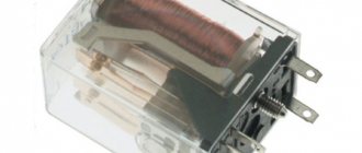
Thyristor exciters are economical, not difficult to operate and set up. Made in the form of a free-standing cabinet.
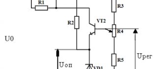
Below is a diagram and description of an electronic installation with thyristor control, which makes it clear what the device consists of:
The design of the device represents:
- A controlled rectifier that supplies power to the field winding of a synchronous motor. Represents a block of thyristors with a pulse-phase control system.
- A reactor representing the input transformer.
- Field damping module.
- Testing system.
- A measurement unit that controls the current level at the output of the exciter voltage and stator current.
- Protection module and alarm unit. Provides protection for fault indication of automatic control and diagnostic systems.
Supplied together with a relay contact control unit for starting the engine. Has a digital or analog control system.
The thyristor exciter allows:
- Apply voltage to the field windings when the electric motor is not operating, for test mode.
- In direct start mode, it supplies voltage to the field windings to maintain the function of stator current and sliding current.
- During reactor start-up, excitation is supplied after the shunt switch is turned on.
- Smooth (asynchronous) start with a high-voltage soft start device.
- Provides synchronous starting using a high-voltage frequency converter.
The electronic exciter controls and maintains normal operation. At the same time, it ensures the safety of the equipment, for which a protection unit is needed:
- Protects output circuits when the excitation current exceeds the initially set value.
- Protects input circuits when network currents exceed a preset one.
- Damage to the insulating circuit.
- Emergency shutdown.
- From a phase rotation error.
- No power tension.
- Errors in synchronizing the motor with the network parameters.
- In case of emergency of the electronic voltage unit.
- Long startup, different from the specified one. The start duration is set programmatically. Exceeding the start time is considered an error.
- Alert about asynchronous progress.
- From external emergencies.
- Protection against control errors is provided.
If the exciter configuration includes protection against a decrease in the insulation resistance of the external circuit, it is additionally equipped with:
- A unit for continuous monitoring of insulation resistance parameters with display on the display.
- The presence of a dry contact in the event of a decrease in insulation resistance, less than two, constant values that are set by service technicians.
The presence of a control unit allows you to keep the voltage in the stator, as well as the performance or excitation coefficient, within the tolerance limits in automatic mode. Characteristics are set during commissioning or remotely.
The appearance and internal design are shown in the photo:
Differences between synchronous and asynchronous motors
The characteristic distinctive features of such installations are the design specificity of the inductors. It is impossible to distinguish between “synchronous” and “asynchronous” by external signs, unless, of course, the latter has additional cooling fins.
The synchronous principle of operation is that the rotor has a winding with independent transmission of electrical voltage. A motor with an asynchronous circuit has a current that is supplied by the magnetic field of the stator.
But the armatures of both types of motors do not have serious design differences. These types create a magnetic field, and in a synchronous electric motor the magnetic fields of the inductor and armature communicate with each other, and the speed indicators of the elements are identical.
“Asynchronous” devices are equipped with slip rings and metal plates with a short circuit in the rotor slots. These components are designed to provide a difference in the magnetic fields of the rotor and stator by the amount of slip.
The following disadvantages are characteristic of asynchronous motors:
- Installations do not withstand loads well
- Starting is carried out with significant effort
- The speed of rotation is easily changed due to the load on the shaft
To get rid of such shortcomings, they first came up with an “asynchronous machine” with a phase inductor, but then it was the turn of a synchronous machine.
Principle of operation
The constant speed of rotation of a synchronous electric motor is achieved through the interaction between a constant and rotating magnetic field. The rotor of a synchronous electric motor creates a constant magnetic field, and the stator creates a rotating magnetic field.
The operation of a synchronous electric motor is based on the interaction of the rotating magnetic field of the stator and the constant magnetic field of the rotor
Stator: rotating magnetic field
Three-phase alternating voltage is supplied to the windings of the stator coils. As a result, a rotating magnetic field is created, which rotates at a speed proportional to the frequency of the supply voltage. You can read more about how a rotating magnetic field is formed using a three-phase supply voltage in the article “Three-phase asynchronous electric motor”.
Interaction between rotating (at the stator) and constant (at the rotor) magnetic fields
Rotor: constant magnetic field
The rotor winding is excited by a direct current source through slip rings. The magnetic field created around the rotor, excited by direct current, is shown below. Obviously, the rotor behaves like a permanent magnet, since it has the same magnetic field (alternatively, one can imagine that the rotor is made of permanent magnets). Let's consider the interaction of the rotor and the rotating magnetic field. Suppose you give the rotor an initial rotation in the same direction as the rotating magnetic field. The opposite poles of the rotating magnetic field and the rotor will be attracted to each other and they will stick together using magnetic forces. This means that the rotor will rotate at the same speed as the rotating magnetic field, that is, the rotor will rotate at a synchronous speed.
Magnetic fields of the rotor and stator linked to each other
Types of installations
In today's industrial production and household appliances, synchronous motors solve a variety of problems. But their designs are different, and several categories can be distinguished into which the units are divided. They can be distinguished by the following characteristics:
- Supply voltage
- Operating thrust frequency
- Speed
Motors are also divided into the method of obtaining the magnetic field of the inductor:
- With an exciting winding on the rotor - the synchronization force occurs when powered by a transformer.
- With a magnetic inductor - a permanent magnet is placed on the shaft, but it does not require additional power.
- With a reluctance rotor - the core allows the refraction of magnetic lines to pass through, which triggers the component. Due to the action of the magnetic field, the longitudinal and transverse elements in the inductor have different indicators, which leads to the rotation of the plates behind the field.
The motors are also divided based on the placement of the working windings. These are straight, located on the stator, and reverse, which are on the rotor.
Functional modes
The bulk of synchronous electric motors are equipped with a reversible option. They can be used for different purposes, and the existing two modes differ in different methods of transferring actions to the machine. A synchronous electric motor operates according to the following regulations:
- Generator mode
- Synchronous compensator
- Engine mode
In the first option, electric motors are used, equipped with phase windings located on the stator. This greatly simplifies the process of transferring performance to the power grid. Current generation is carried out under the action of the electromagnetic field of the excitatory winding of the generator with stator windings.
In the second case, when idling, the unit takes enormous power from the network. In practical implementation, this mode is used to improve the performance index or to stabilize the mains voltage parameters.
The third mode manifests itself when operating three-phase electrical voltage is transferred to the stator windings. Next, the armature electromagnetic field begins to push the magnetic field of the inductor, and the shaft begins to rotate. But in reality, the engine mode is not so simple, since powerful units fail to achieve speed indicators, then methods and connection diagrams were invented for starting.
Special synchronous units
There is another reason for classifying synchronous engines. For example, in automation, low-power electric motors with performance indicators of up to 500 W are used. According to this principle, the following types are distinguished:
- Hysteresis
- Stepper
A hysteresis motor is understood as a synchronous circuit device in which torque is generated when hysteresis occurs when the ferromagnetic material of the inductor is remagnetized. The armature here resembles the stator of a conventional AC motor, and the rotor is made in the form of a steel cylinder without winding.
The rotor is a permanent magnet that turns at synchronous speed. This motor is characterized by simplicity, reliability, good starting torque and high efficiency.
Stepper electric motors are installations endowed with the ability to change the command, which is transmitted in the form of pulses to a certain rotary angle or to the rotor position without feedback indicators. Stepper motors can be of different types - with an active rotor or reactive, and they can operate in different modes.
Starting synchronous electric motors
This is the most difficult task in the operation of an electric synchronous motor. This is due to the specifics of the design.
For a long time, the operation of the “synchronous machine” depended on the accelerating asynchronous electrical mechanism, which was connected to the “synchronous machine”.
Asynchronous motors do not require special devices for activation - it is enough just to supply voltage to the armature windings. As soon as the speed has reached the required values, the accelerating unit is turned off.
The magnetic fields communicating in the electric motor themselves start it in synchronization mode. Acceleration is done by a different motor with a power of 10-15% of a car with similar parameters.
But if you need to run a kilowatt electric motor, then you need to use an accelerating engine with a performance rating of 100 watts. This is enough for the installation to function under load and without traction.
Excitation systems for synchronous machines
The characteristics of the excitation system are determined by a combination of the properties of the excitation winding power source and automatic control devices. Excitation systems must provide:
1) reliable power supply to the rotor winding of a synchronous machine in all modes, including during accidents;
2) stable regulation of the excitation current when the load changes within the nominal limits;
3) sufficient speed;
4) forcing excitation.
Excitation systems are classified depending on the power source - the excitation winding - into dependent (self-excitation) and independent. Dependent - powered from the main or additional armature winding of the excited generator . The independent one is powered from other sources (from the station’s own buses, from an exciter or an auxiliary generator).
Among the independent excitation systems there are:
a) direct excitation systems,
in which the rotor of the exciter or auxiliary generator is located on the same shaft with the rotor of a synchronous machine or is interfaced with it by a speed reducer;
b) indirect excitation systems,
in which the rotor of the exciter or auxiliary generator is driven by a synchronous or asynchronous motor specially installed for this purpose.
Until the 60s of the last century, direct electric machine excitation systems were used,
in which the excitation winding of a synchronous machine is powered by a DC collector generator - exciter (Fig. 24.26, a).
In accordance with GOST 533-76, GOST 5616-81 and GOST 609-75, turbo and hydrogen generators and synchronous compensators can only have the most reliable direct excitation system or self-excitation system. But electric machine excitation systems, due to switching conditions, cannot be used in turbogenerators with a power of 200 MW and above, whose excitation power exceeds 800-1000 kW.
, valve excitation systems are becoming more widespread
. They are used for low-power synchronous motors and generators, as well as for large turbogenerators, hydraulic generators and synchronous compensators, including for maximum power plants.
There are three main types of valve excitation systems.
1. Independent valve excitation system
(Fig. 24.26,
b),
in which the excitation winding is powered from an auxiliary synchronous generator, the rotor of which is mounted on the shaft of the main generator. In this case, rectifier circuits use semiconductor valves (silicon diodes or thyristors) assembled using a three-phase bridge circuit. When regulating the generator excitation, the capabilities of controlling rectifiers and the ability to change the voltage of the auxiliary generator are used simultaneously.
2. Brushless excitation system,
which differs from an independent valve system (Fig. 24.26,
b
) in that it has an inverted auxiliary synchronous generator, in which the alternating current winding
3
is located on the rotor. Rectifier 5, receiving power from this winding, is located on the shaft of the main generator. The advantage of this system is the absence of sliding contacts, which in powerful turbogenerators must be designed for thousands of amperes
3
.
A self-excitation system
(Fig. 24.26,
c),
in which the excitation winding is powered from the main or additional armature winding.
AC rectification is carried out using thyristors. Energy is collected using transformers 9
and
7,
connected respectively in parallel and in series with the stator winding.
Transformer 7
makes it possible to boost excitation during close short circuits, when the voltage on the armature winding is significantly reduced. The self-excitation system has higher reliability and lower cost compared to other systems due to the absence of an exciter or auxiliary generator.
Important parameters of excitation systems are the nominal rate of rise of the excitation voltage, the nominal excitation voltage, and the excitation boost factor.
Rated excitation voltage
- voltage at the terminals of the excitation winding when powered by its rated excitation current and winding resistance reduced to the design operating temperature.
Excitation boost ratio
- the ratio of the highest steady-state value of the excitation voltage to the rated excitation voltage.
The excitation circuit provides a special device, with the help of which in an emergency it is possible to quickly reduce the excitation current to zero ( extinguish the magnetic field
). For example, in case of internal short circuits in the stator winding, field suppression is carried out using a field suppression machine, which closes the field winding to a special suppression resistor.
To keep a synchronous machine in synchronism when the network voltage decreases during remote short circuits, they resort to forcing its excitation current. The forcing is performed automatically by the relay protection of the machine. The efficiency of forcing is characterized by the excitation forcing factor.
Modern overclocking method
This installation will cost more, so experts advise using “asynchronous”, despite the fact that it is obsolete and has a large number of shortcomings. But it was precisely its functioning circuit that formed the basis of synchronous engines and served to reduce the size and cost of the installation.
A rheostat is used to close the windings on the inductor. Then “synchronous” turns into “asynchronous”. It is easy to start - you need to transfer electricity to the armature windings.
When accelerating the synchronous speed, the rotor can swing and calm the inductor windings. After reaching the desired speed, the current is transmitted to the rotor windings, and the synchronous mode is activated on the engine.
But this method can be used if there are engines with rotary winding available. If there is a permanent magnet, an additional motor is installed for acceleration.
Where can I buy
Different types of synchronous motors are offered at different sites. These include specialized stores selling such products, and people who previously used these motors and decided to sell them as unnecessary.
It is worth paying special attention to online stores. These platforms have recently gained wide popularity and offer a fairly wide range of different engines with a synchronous interaction scheme.
But you can also point to sites that also have used motors purchased at various auctions abroad. Their quality is usually very good, despite some minor wear. But when choosing a product, it is better to use recommendations.
How to choose: useful tips
Finding a synchronous electric motor on the market is not a problem, but often the operation of the device depends on the correct choice. Therefore, when purchasing a unit, you should adhere to the following rules:
- How to operate the motor. Based on this criterion, the type of engine is selected - open, closed, protected. Protection can be from moisture, temperature and the influence of an aggressive environment. But there are also special means with which you can avoid sparks in the motor.
- How is the motor connected to the consumer?
By paying attention to these points, you can choose a real synchronous electric motor without any problems.
Manufacturers
Companies that manufacture synchronous electric motors can be divided into:
- Russian
- Near abroad
- Far abroad.
Among the domestic manufacturers of such products are the Armavir Electrical Equipment Plant, the Baranchinsky Electromechanical Plant, the Vladimir Electric Motor Plant, VNITI EM, EVI, IOLLA, the Elektrodvigatel enterprise from Krasnogorsk, the Voronezh MEL and other production facilities located in Russian cities.
In the near abroad, electric motors with a synchronous circuit are produced at the Belarusian “Electrodvigatele” and Polesyeelectromash, the Ukrainian “Ukrelectromash”, “Elektromashina”, “Electromotor”, “Electrotyazhmash” and the Moldavian “Electromash”.
In foreign countries, the leading companies are the American Ametek, Emerson Electric Corporation, General Eletric, Johnson Electric Holdings Limited, Regal Beloit Corporation, the German Baumueller, Liebherr, Nord, Rexrot Bosch Group, Siemens AG, the Slovenian Domel, the Swiss ABB Limited, Maxon Motor, the Japanese Nidec Corporation and Brazilian WEG.
Advantages and disadvantages
An electric machine with a synchronous circuit has the following advantages:
- High productivity ratios
- The use of "synchronous" in production to increase the power index
- Increased efficiency, which is several times greater than that of an asynchronous machine
- Good degree of strength
- Lack of sensitivity to changes in voltage in the electrical network
But, despite the obvious advantages, there are also a number of disadvantages. This is the complexity of the starting design and the high price of the unit. Synchronous motors are used to start mechanisms that do not require a change in speed.
But powering the rotor winding requires a direct current source, and the inductor rotation frequency can be adjusted using transformers, and this is also expensive. It turns out that “synchronous devices” are used when it is not necessary to frequently turn off or turn on a particular device.
Operating principle of synchronous machines
The operating principle of a synchronous machine is based on the interaction of two types of magnetic fields. One of these fields is formed by the armature, while the other arises around an electromagnet excited by direct current - an inductor. Immediately after reaching operating power, the magnetic field created by the stator and rotating inside the air gap meshes with the magnetic fields at the poles of the inductor. Thus, in order for a synchronous machine to reach its operating speed, a certain amount of time is required to accelerate it. After the machine accelerates to the required frequency, power is supplied to the inductor from a DC source.