How to choose a meter for your home yourself
Despite the seeming complexity of choosing to replace or install a new electric meter, it will be easy for a home electrician to do this if you familiarize yourself with the basic selection criteria.
Types of meters by operating principle
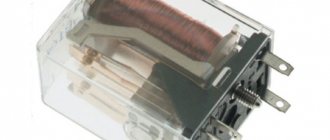
Until recently, only induction mechanical (electromechanical) meters
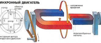
. In them, the consumed current flows through the measuring coil of the copper wire, exciting a magnetic field. This field, acting on the disk, causes it to rotate at a speed proportional to the amount of current consumed. Through a system of gears, the rotational movement is transmitted to the counting device.
Electromechanical meters have been replaced by hybrid ones, which are found in two designs: Induction electronic and Electronic mechanical.
In an induction electronic meter
, as in a mechanical one, there is a coil that rotates the disk. Rotating, it affects the sensor, which generates impulses sent to an electronic device with a digital display.
In an electronic mechanical counter
it's the other way around. The current sensor is a solid-state element, as in a static meter, and the counting device is installed mechanically, as in an induction meter.
The above counters are now being replaced by modern static counters
, having no mechanical parts. They use a solid-state electronic element as energy consumption sensors, from which the signal is sent to an electronic unit with a digital display.
Selecting a meter based on operating principle
The table shows the main technical characteristics of electricity meters. Any of them is suitable for installation in an apartment or house. Therefore, when choosing, you need to proceed from the volume and time of day of electricity consumption.
| Table of main technical characteristics of existing types of meters | |||||
| Characteristic | Induction mechanical | Hybrid | Electronic static | Note | |
| Induction electronic | Electronic mechanical | ||||
| Price | low | average | average | high | |
| Reliability | high | average | average | low | |
| Repair cost | low | average | average | high | |
| Verification frequency, years | 6-8 | 6-8 | 4-16 | 4-16 | Indicated in the passport |
| Operating voltage, V | 220, 380 | 220, 380 | 220, 380 | 220, 380 | Indicated in the passport |
| Maximum load current, A | 60, 100 | 60, 100 | 60, 100 | 60, 100 | Indicated in the passport |
| Number of phases | 1, 3 | 1, 3 | 1, 3 | 1, 3 | Indicated in the passport |
| Starting current | high | high | short | short | Indicated in the passport |
| Accuracy class (% error) | 2 or more | 2 or more | 1 or less | 1 or less | Operation of class more than 2 is prohibited |
| Day/night mode | No | There is | No | There is | Helps reduce costs at night |
| Remote transmission of readings | No | There is | No | There is | Allows you to transfer data to the energy supply company |
| Measuring electrical network parameters | No | There is | No | There is | Allows you to control voltage and current consumption |
| dimensions | overall | overall | overall | small-sized | Indicated in the passport |
If at night electricity is consumed in small quantities, then the best choice would be an induction mechanical or induction electronic meter, since it is inexpensive, reliable, durable and there is practically no need to incur the cost of repairing it.
It is worth noting that induction meters, unlike electronic ones, have less sensitivity, and if the current consumption is small, for example, it is only turned on to charge a cell phone, then the meter will not count.
Although Static meters are twice as expensive and less reliable, if more than 30% of the electricity is consumed at night, then they quickly pay for themselves and provide good savings, since they have a charging function. This is when it is possible to keep track of electricity consumption at night and during the day separately. The cost of nighttime electricity is significantly lower.
Electricity supply companies are also interested in installing static electronic meters due to excess power at night and avoiding the reduction of induction meters using magnets and laying in a horizontal position.
Based on the above, we can conclude that a single-phase two-wire electric meter of any operating principle, designed for a voltage of 220 V and a current of 60 A, is suitable for private housing.
(maximum power is determined by multiplying the current by voltage and will be 13.2 kW).
Power consumption of electrical appliances
The theoretical maximum power that will be consumed if all electrical appliances in the apartment are turned on simultaneously is not difficult to calculate from the data given in the table. To do this, you need to add up the power of all available electrical appliances. But such a case is unlikely.
| Table of power consumption and current for household electrical appliances | |||
| Household electrical appliance | Power consumption, kW (kVA) | Current consumption, A | Consumption mode |
| Incandescent light bulb | 0,06 – 0,25 | 0,3 – 1,2 | Constantly |
| Electric kettle | 1,0 – 2,0 | 5 – 9 | Up to 5 minutes |
| Electric stove | 1,0 – 6,0 | 5 – 60 | Depends on operating mode |
| Microwave | 1,5 – 2,2 | 7 – 10 | Periodically |
| Electric meat grinder | 1,5 – 2,2 | 7 – 10 | Depends on operating mode |
| Toaster | 0,5 – 1,5 | 2 – 7 | Constantly |
| Grill | 1,2 – 2,0 | 7 – 9 | Constantly |
| Coffee grinder | 0,5 – 1,5 | 2 – 8 | Depends on operating mode |
| Coffee maker | 0,5 – 1,5 | 2 – 8 | Constantly |
| Electric oven | 1,0 – 2,0 | 5 – 9 | Depends on operating mode |
| Dishwasher | 1,0 – 2,0 | 5 – 9 | Maximum from the moment of switching on until the water is heated |
| Washing machine | 1,2 – 2,0 | 6 – 9 | Maximum from the moment of switching on until the water is heated |
| Dryer | 2,0 – 3,0 | 9 – 13 | Constantly |
| Iron | 1,2 – 2,0 | 6 – 9 | Periodically |
| Vacuum cleaner | 0,8 – 2,0 | 4 – 9 | Depends on operating mode |
| Heater | 0,5 – 3,0 | 2 – 13 | Depends on operating mode |
| Hair dryer | 0,5 – 1,5 | 2 – 8 | Depends on operating mode |
| Air conditioner | 1,0 – 3,0 | 5 – 13 | Depends on operating mode |
| Desktop computer | 0,3 – 0,8 | 1 – 3 | Depends on operating mode |
| Power tools (drill, jigsaw, etc.) | 0,5 – 2,5 | 2 – 13 | Depends on operating mode |
To more accurately calculate the theoretical total power consumption of electrical appliances, it must be taken from the labels or operating instructions on them. Power is indicated in watts (W or VA) or kilowatts (kW or kVA). 1 kW=1000 W.
Advantages and disadvantages
Single-phase electric meters are used to meter electricity, however, each type of meter has its own advantages and disadvantages. Therefore, we will consider the pros and cons for each of them in order.
Induction electricity meters have the following advantages:
- Simple design and lower cost;
- An accessible operating system that allows even an inexperienced consumer in electrical engineering to determine energy consumption;
- Such electricity meters are much more resistant to voltage surges and poor quality of electrical energy in domestic circuits;
- Longer service life.
Significant disadvantages of induction models include their large dimensions and vulnerability to the simplest methods of electricity theft. Over time, malfunctions begin to appear, and consumers often experience self-propelled phenomena.
Single-phase electronic electricity meters are characterized by the following advantages:
- Smaller dimensions compared to induction models;
- There are no rotating parts, which increases wear resistance and allows for less frequent checking of the electricity meter;
- They can implement multi-tariff metering of consumed electricity; some models have a remote automatic polling function;
- Allows you to record both active and reactive components, determine the maximum and minimum load for a day, week, month;
- They have a higher accuracy class.
The disadvantages of electronic models include their high cost; they are quite difficult to repair due to their complex circuitry and the need for subsequent configuration in the laboratory. They are also extremely sensitive to the quality of electricity flowing through them.
Electrical diagram for connecting an electric single-phase meter
The drawing shows the electrical circuit of the panel and electrical wiring. An electric meter is usually installed in an electrical panel along with circuit breakers and RCDs.
Electric energy is supplied to a single-phase meter from the electrical network through a panel installed in the entrance of the house. A separate circuit breaker is installed in the panel for each apartment and the wires from it go directly to the meter. One wire is called phase, the second is called zero, and the third is called ground.
In apartments and houses of old construction, electrical wiring was laid without a grounding wire. It does not directly participate in the operation of electrical wiring and is intended solely to increase safety during the operation of electrical appliances.
According to GOST R 52320-2005, a connection diagram must be marked on the meter body next to the terminals for connecting the wires. In the photo it is a yellow plate.
According to the rules, phase wire L coming from the electrical network is connected to the first (left in the photo) terminal of the terminal. And from the second it is fed into household electrical wiring. The third and fourth contacts of the terminal are connected to each other inside the meter and are intended for connecting the neutral wire N.
A three-phase meter is connected according to the same principle. Phase A is supplied to the first contact, and phase A is removed from the second. Phase B is supplied to the third, and phase B comes out from the fourth. Phase C is supplied to the fifth, and removed from the sixth. The neutral wire N is supplied and removed from the seventh and eighth contacts, respectively.
Attention! Before replacing or installing the meter, you must turn off the voltage supply to it by turning off the circuit breaker in the distribution panel on the landing and check the absence of phase on the supply wires using a phase indicator.
Connecting an electricity meter
Having considered the functional principles of the electronic meter, it’s time to move on to the practical part. We will talk about how to properly install a single- and three-phase meter.
The installation diagram for an existing power grid is directly indicated on the device body or its documentation. It is different for 220 V and 380 V networks (one or three phases, respectively). In general, an electric meter, regardless of its type (electronic or induction), if it is designed to operate on one phase, is connected according to the following diagram:
Installation of a three-phase electricity meter is performed a little differently:
The sequence of contacts may differ for different models.
In addition, there are special cases when the electric meter is connected to the line not directly, but through current transformers:
After installing the metering device (unless, of course, it is done in the interests of personal information), you need to contact the service personnel of the organization supplying electricity. The latter will check the correct connection, take the initial readings of the device and record its factory data. Afterwards, the metering device must be sealed in order to prevent subsequent changes to the connection diagram.
Electric meter device
A friend's display stopped working on his meter. I called an electrician and without thinking twice, he replaced the meter with a new one. As a result, I got this electrical device to study the device.
The front panel of the meter was fixed with three latches. After removing it, a picture was revealed, as in the photograph. The entire electrical circuit of the meter is assembled on a printed circuit board with double-sided mounting. A display, control buttons and a CR2032 battery with a voltage of 3 V are soldered on the front side, the same ones installed in computers. The battery is required to save settings and meter readings in the event of a power outage.
The battery is the bottleneck of the meter, as its shelf life is about 10 years. If it fails, the day-night settings and meter readings will be reset to zero in the event of a power outage. The battery is welded to terminals that are soldered into the board. To replace the battery you will have to do some soldering with a soldering iron.
The printed circuit board is secured with four latches and can be easily removed. All other elements of the circuit are soldered on the reverse side of the printed circuit board. The soldering is done neatly, there are no traces of flux. I liked the workmanship of the Mercury counter.
A shunt, which is a metal plate with a calibrated resistance of a very small value, serves as a measuring sensor for the consumed electricity. When current flows through the shunt, according to Ohm's Law, a voltage drop occurs, which is supplied to the microprocessor.
The analog signal is converted by a microprocessor into a digital one, which is stored, and the current readings of electricity consumption are displayed on the display. In the photo the shunt is copper colored.
I decided to try to repair the meter. I measured the voltage at the terminals of the electrolytic capacitor of the power supply, it was 3.5 V. Taking into account the installed 25 V capacitor, the voltage was clearly below normal.
The power supply has a transformerless circuit with a current-limiting capacitor. Checking the capacitors and diodes showed their serviceability. It was necessary to apply a voltage of 5 V with a current limit of 300 mA to the terminals of the last electrolytic capacitor from a stationary power supply.
Probing the circuit elements with your fingers revealed that the lower left corner of the microprocessor gets very hot. It became clear that it was faulty, and it was not possible to fix such a fault at home.
Features and principle of operation of three-phase electricity meters
Like single-phase, three-phase electricity meters consist of the following elements:
- frame;
- measuring mechanism;
- computing mechanism;
- display on which the readings are displayed.
The principle of their operation is the analog-to-digital conversion of the input signal into a digital code. The signal is received by current transformers and resistive dividers (voltage sensors). The digital signal processor acts as a converter.
The meter is equipped with an integrated memory module, which provides information storage, as well as an RS485 digital communication channel for remote data transfer.
Mounting the meter in the panel on a DIN rail
In the electrical panel, all modern installation electrical products, such as meters, automatic machines, RCDs and others, are mounted in an easily removable way on a DIN rail, which electricians also call a mounting rail.
The DIN rail is 35 mm wide and in accordance with GOST R IEC 60715-2003 “Low-voltage distribution and control equipment. Installation and fastening on rails of electrical devices in low-voltage complete distribution and control devices" is designated T35
. Previously, DIN rails were made of aluminum alloy, as in the photo. Modern ones are made of sheet steel by stamping.
Some meter models are equipped with their own DIN rails. For example, the Mercury 200 electric meter, which is installed in my apartment, included a non-standard DIN rail, although the mounting location had a standard size of 35 mm, which allows it to be mounted on a standard DIN rail.
The meter installed in the panel is sealed and can be removed only after removing the seal and cover. Under it there are two rectangular holes (indicated by arrows in the photo). To remove the meter, you need to simultaneously insert the blades of two flat-head screwdrivers into these holes, the movable latches will disengage from the DIN rail, and move the lower edge of the meter away from the panel wall.
Criterias of choice
There are several parameters to consider when selecting a suitable device:
- number of tariffs. Multi-tariff models are popular, taking into account light consumption depending on the time of day and load on power grids. In two-tariff devices, the division is only between day and night. A single-tariff meter has a fixed payment per kW/h. A suitable model is selected taking into account your lifestyle. If, for example, you often have to use household electrical appliances at night, then in order not to overpay for light, it is better to take a multi-tariff meter;
- accuracy class. This parameter is the error of readings on the basis of which electricity consumption is estimated. If the error is large, weak currents are not detected by the device (analogy with water dripping from a faucet), which the services that supply energy do not like. Therefore, modern models are required to have an accuracy class of 2.0. There is no point in choosing a model with a large indicator, since energy consumption will only increase;
Difficulty of choice
- current load. To understand this criterion, you need to measure the value of the current at the entrance to the apartment (using current clamps. Another way is to determine the current load by the cross-section of the conductor cores. There is another option - calculate the total power of household appliances in the house with a reserve (possibly in the future other consumers will connect). If the figure is 10 kW, then a 60 A meter will suffice. If more, then you will need a device with 80 or 100 A.
Note! To connect a 100 A electric meter, you must obtain special permission from the energy supply company.
How to reliably connect wires to the meter
The reliability of all apartment electrical wiring depends on the quality of the connection of the wires to the meter. Here, due to inexperience, home electricians can make a mistake.
If a sufficient length of the bare end of the wire is not left when removing the insulation, it will fall under the clamping strip of the terminal and over time will lead to a breakdown in contact, which will lead to an unstable supply of electricity to the apartment wiring.
The reliability of connecting wires to the meter terminals can be increased if the ends of the wires are bent, as shown in the photo. With this connection, the contact area of the wire with the terminal will double.
The photo shows a view of the terminals from the wire entry side. To connect the wires to the meter, you need to unscrew the terminal screw, insert the wire all the way and tighten the screw with sufficient force.
When winding the wire into the terminal hole, you may not be able to get into it, so after tightening the screw, you need to pull the wire with sufficient force to make sure it is securely fastened.
Advantages and disadvantages
Differences between manufactured devices: connection method, type of measured values, design. Some models are connected directly to the power supply and operate from a transformer. Others are connected to the network, operating from a 220 V network.
Metering device "Energomera CE101"
Single-phase electricity meter and its design:
- induction. Energy consumption is measured by an aluminum disk spinning in a magnetic field. The power consumption is reflected in its rotation speed;
- electronic. Electrical power is measured in pulses.
Recently, electronic single-phase meters have become popular, characterized by the following advantages:
- high accuracy (0.5-2 units);
- multiple tariffs;
- the quality of energy consumed is controlled;
- the ability to measure reactive power and control flow in two directions;
- protected from electricity theft;
- there is a digital interface on which indicators are displayed;
- serves for a long time (about 30 years).
A single-phase meter also has a number of disadvantages, which it is better to immediately pay attention to. Such models have low resistance to lightning impulse discharges. When exposed to them, the device can fail for a long time. Another disadvantage is that not all users trust them, like time-tested induction electricity meters.
Conventional induction device
The procedure for sealing the meter
According to the requirements of the PUE, the meter must be sealed to prevent theft of electricity. Therefore, before replacing an old or failed meter, it is necessary to invite a representative of the electricity supplier to draw up a Certificate of Removal of Seals. In the event of an emergency, for example, the power supply to an apartment or house has stopped due to a meter failure, you should contact the emergency service. Their electricians have the right to break seals with the execution of an act.
Immediately after self-installation of the meter into the panel due to repair, verification or replacement, an authorized person of the electricity supplier is re-invited to seal the meter. You will need to present a certificate of removal of the seal from the emergency service and a passport for the electric meter. The photo shows a yellow filling.
When installing an electric meter, the following rules must be observed. The wires supplying electricity from the entrance to the apartment should not have connections. The electricity meter must be installed at a height of 0.4 to 1.7 m and must be sealed, regardless of whether it is located in an apartment or in the entrance of a house.
The circuit breaker included in the electrical wiring in front of the electric meter is sealed only if it is installed in the apartment. The design of the circuit breaker installed in front of the meter in the apartment must provide for the possibility of sealing it.
Maintenance and verification of a three-phase electric meter
Maintenance of three-phase electric meters is carried out by employees of certified services who have an electrical safety clearance group of at least 3 (for electrical equipment up to 1000 V), who have undergone safety training and have studied the instructions of the electric meter manufacturer. Maintenance before verification involves replacing the lithium battery.
The calibration interval is set by the manufacturer and indicated in the technical documentation. Verification of a three-phase electric meter is performed:
- immediately after release;
- after renovation;
- after the verification interval has expired.
The verification procedure is carried out according to the YUTLI.422863.001MP method. Verification data is applied to the seal and is also indicated in the certificate and (or) technical passport.
Designation of digital meter indicators
Based on the electronic meter data, several readings are determined:
- Energy consumption for a specific time period. You will need to subtract the initial readings from the final readings. If necessary, the calculated data is multiplied by the transformation coefficient;
- Connecting household appliances and lighting at a certain point. Set by the indicator light coming on/off.
- Power parameters, passing current values, network and meter overload processes.
Digital devices can be programmed for day and night tariffs. To do this, just select the counting time.
Reliability of readings and need for repairs
A high-quality digital electricity meter is highly accurate. You can check the parameters without violating the integrity of the case and seals as follows:
- After the power supply is stopped, the indicator stops. If recording continues, the device is faulty.
- The meter always buzzes during operation; a problem is indicated by the self-propelled machine.
- The readings are distorted when all household appliances are turned off. The presence of a self-propelled vehicle must be checked.
Testing is best done at night, under conditions of minimal load on the power grid. If there is no self-propelled gun, there are no indicator pulses for 15 minutes. A pulse that occurs when the connection is not made means a breakdown.
Only employees of the energy saving company should repair the digital meter. The user contacts the authority to obtain permission to check and replace the device.
Main characteristics of digital meters
On the territory of the Russian Federation, devices began to be used since the privatization of the energy industry and the rise in price of electricity. Electronic devices have a number of positive characteristics:
- accuracy of readings during rapid voltage changes or decreases;
- electricity metering at several tariffs;
- counting different types of energy using one device;
- the power, quantity and quality of energy resources are simultaneously measured;
- storing data in memory and having user access to it;
- preventing unauthorized access and theft of electricity;
- remote readings and preliminary calculation of losses;
- compatibility with automatic services for commercial electricity metering.
The device cannot be hacked by attackers and connected to it to steal electricity. The product inspection interval is 16 years.
Design and operating principle
The measuring device is compatible with single-phase and three-phase AC circuits. Its design is presented:
- housing made of heat-resistant plastic or metal with a terminal block;
- display - LCD indicator, which displays data and time, or mechanical;
- power source for the electronic circuit;
- current transformer – performs the functions of a meter;
- a microcontroller that converts the input signal into electrical quantities;
- telemetric output for integration with ASKUE;
- clock – allows you to track real time and dates;
Appearance of an electronic electricity meter
- supervisor - monitors input voltage fluctuations and sends a reset command to the microcontroller when the voltage turns off or on;
- control system;
- an optical port that allows you to take readings from the device.
A digital counter can be programmed via the optical port.