A rational power supply scheme depends on a technically sound selection of transformer power, which affects operating costs and payback, which is possible in 6–10 years.
When choosing a transformer, they are guided by the following criteria:
- Power supply category
– the number of transformers is determined. Objects of power supply category III – one transformer. Objects of II and I categories of power supply - two or in some cases three transformers. - Overload capacity
- determination of the power of the transformer. - Daily load distribution schedule
– recording loads by time and days of the week. - Economical mode of operation of the plant.
Selecting the number of transformers
Single-transformer substations are used in two cases. Firstly, for objects of category III power supply. Secondly, for consumers who have the ability to back up power supply using ATS (automatic transfer switch) from another power source.
When supplying consumers of categories I and II in emergency mode at a two-transformer substation, after the ATS is triggered, the entire transformer takes on the load of the faulty one. Therefore, its overload capacity should be sufficient to replace a failed transformer. In normal mode, transformers operate underloaded, which is not economically feasible. Therefore, in an emergency, some consumers of category III power supply are disconnected from the network.
The power supply break for category II facilities is limited to one day. To restore the scheme, a strategic warehouse reserve of equipment necessary to eliminate the accident is required. In this case, the power of the new transformer must be identical to the one being replaced. Thus, the amount of backup equipment is reduced.
Selection of transformer power
The choice of power of transformers installed in transformer substations must be made taking into account their overload capacity in normal and post-emergency operating modes:
(2.2)
≥ ×
where is the rated power of the transformer (tables 2.2, 2.3);
– transformer load factor;
– total calculated load power on busbars 0.38 kV TP.
For village networks in normal mode, two-transformer substations are in the range of 0.60...0.65. If in normal mode K3 < 0.93, then in post-emergency mode during maximum loads (total duration up to 6 hours a day for no more than five days), the transformer remaining in operation can be loaded up to 140% of its rated power.
In this regard, when designing distribution networks, the rated power of the transformer can be selected from the condition:
. (2.3)
For two-transformer substations with oil transformers, the permissible emergency overload in the event of shutdown of one of the transformers during the maximum period should be taken in accordance with Table 2.1.
Table 2.1 – Short-term overload of oil transformers in post-emergency modes
| Overload, % | |
| Overload duration, min | 1,5 |
For single-transformer substations, the load of which is not expected to increase, the rated power of the transformer can be selected from the condition:
. (2.4)
Taking into account possible load growth, the rated power of the transformer should be selected from the condition:
, (2.5)
where k is a coefficient taking into account the increase in load.
If it is necessary to take into account the load backup of another substation via a jumper with a voltage of 0.38 kV, then in approximate calculations the rated power of the transformer can be selected from the condition:
, (2.6)
where is the reserved load.
Table 2.2 - Main characteristics of three-phase oil two-winding transformers with a voltage of 10 kV
| Transformer type | Snom, kVA | Catalog data | Calculation data | |||||
| Unn, kV | Uк,% | ΔРК, kW | ΔРХ, kW | Iх, % | RT, Ohm | Ht, Ohm | ΔQх, kvar | |
| TM-25/10 | 0,4 | 4,5 | 0,6 | 0,13 | 3,2 | 152,3 | 0,8 | |
| TM-40/10 | 0,4 | 4,5 | 1,00 | 0,19 | 3,0 | 98,1 | 1,2 | |
| TM-63/10 | 0,4 | 4,5 | 1,28 | 0,26 | 2,8 | 37,0 | 70,5 | 1,76 |
| TM-100/10 | 0,4 | 4,5 | 1,97 | 0,36 | 2,6 | 19,7 | 40,7 | 2,6 |
| TM-250/10 | 0,4; 0,69 | 4,5 | 3,7 | 0,82 | 2,3 | 5,92 | 17,0 | 5,75 |
| TM-320/10 | 0,4; 0,23 | 5,5 | 6,2 | 0,91 | 0,7 | 6,05 | 16,1 | 2,24 |
| TM-400/10 | 0,4; 0,69 | 4,5 | 5,5 | 1,05 | 2,1 | 3,44 | 10,7 | 8,4 |
| TMZ-400/10 | 0,4 | 5,5 | 5,5 | 1,08 | 4,5 | 3,44 | 13,3 | 18,0 |
| TM-630/10 | 0,4; 0,69 | 5,5 | 7,6 | 1,56 | 2,0 | 1,91 | 8,73 | 12,6 |
| TM-1000/10 | 0,4; 6,3 | 5,5 | 12,2 | 2,45 | 1,4 | 1,22 | 5,36 | 14,0 |
Table 2.3 - Main characteristics of three-phase oil two-winding transformers with a voltage of 6 kV
| Transformer type | Snom, kVA | Catalog data | Calculation data | |||||
| Unn, kV | Uк,% | ΔРК, kW | ΔРХ, kW | Iх, % | RT, Ohm | Ht, Ohm | ΔQх, kvar | |
| TM-25/6 | 0,4 | 4,5 | 0,6 | 0,13 | 3,2 | 39,6 | 54,8 | 0,8 |
| TM-40/6 | 0,4 | 4,5 | 0,88 | 0,19 | 3,0 | 19,8 | 35,3 | 1,2 |
| TM-63/6 | 0,4; 0,23 | 4,7 | 1,4 | 0,36 | 4,5 | 14,0 | 26,1 | 2,83 |
| TM-100/6 | 0,4 | 4,5 | 1,97 | 0,36 | 2,6 | 7,09 | 14,6 | 2,6 |
| TM-160/6 | 0,4; 0,23 | 4,5 | 2,65 | 0,46 | 2,4 | 4,11 | 10,4 | 3,84 |
| TM-250/6 | 0,4; 0,69 | 4,5 | 3,7 | 0,82 | 2,3 | 2,35 | 6,75 | 5,75 |
| TM-320/6 | 0,4 | 5,5 | 6,07 | 1,6 | 2,35 | 6,40 | 19,2 | |
| TM-400/6 | 0,4; 0,69 | 4,5 | 5,5 | 1,05 | 2,1 | 1,24 | 3,86 | 8,4 |
| TM-630/6 | 0,4; 0,69 | 5,5 | 7,6 | 1,56 | 2,0 | 0,69 | 3,07 | 12,6 |
| TM-1000/6 | 0,4; 0,69 | 5,5 | 12,2 | 2,45 | 1,4 | 0,44 | 1,93 | 14,0 |
| TM-2500/6 | 0,4; 0,69 | 5,5 | 26,0 | 4,6 | 1,0 | 0,15 | 0,78 | 25,0 |
For transformers installed at a two-transformer substation, the calculated power is equal to:
, (2.8)
where is the design power of the substation, kVA.
Transformers accepted for economic load intervals are checked according to their operating conditions in normal and post-emergency operating modes.
For normal substation operation, transformers are checked for permissible load based on the condition:
Sd.min< Sр < Sd.max, (2.9)
where Sd.min, Sd.max are respectively the minimum and maximum limits of the permissible load of the transformer, determined depending on the type of substation load and the rated power of the transformer, kVA.
For post-emergency operation of the substation, transformers are checked according to emergency design loads based on the condition:
Sav.min. ≤ Sav. ≤ Sav.max.,(2.10)
where Sav.min, Sav.max are respectively the minimum and maximum limits of emergency loads of the transformer, determined depending on the type of substation load and the rated power of the transformer, kVA.
Example:
Let's calculate the radii of circles for given consumers, taking m = 0.1 to VA/:
Table 2.1 Circle radii for cartograms
| R1;mm | R2;mm | R3;mm | R4;mm | R5;mm | R6;mm | R7;mm | R8;mm | R9;mm | R10;mm |
| 9,28 | 28,51 | 19,7 | 44,1 | 30,5 | 35,3 | 7,7 | 21,6 | 28,2 | 34,5 |
One consumer (pig breeding complex) is connected to TP1, which is classified into the second category of power supply reliability, therefore, it will be necessary to install two transformers of the same power at the transformer substation. Let's calculate the coordinates of the location of the TP:
Figure 2.1. – Cartogram of electrical loads
The power of transformers at a transformer substation is determined from the inequality:
ST ≥ Kz S
where Kz is the load factor of transformers, we take it equal to (0.65... 0.7).
From the reference table, we select a two-winding transformer for TP1 and calculate the load factor of the transformer in normal mode ( Kzpr) and the load factor of the transformer in emergency mode (Kzav.). Two TM 320/10 transformers are installed at the substation.
The livestock complex for milk production has its own technological substation. Since it belongs to the second category of power supply reliability, two transformers are installed at the transformer substation.
TP3 supplies one consumer of category II power supply reliability.
3 consumers are connected to TP4 (a residential building with 70 houses, a school, a water tower) of the III category of power supply reliability. Since category III does not require backup power, one two-winding transformer can be installed on the TS. In this case, the transformer is selected on the basis that the load factor of the transformer is equal to 1.
The residential building and the store are connected to one transformer substation TP5. Since these consumers belong to categories II and III of power supply reliability, it is necessary to install 2 transformers at the transformer substations.
TS6 supplies two consumers, the main one of which is a potato storage facility, which belongs to the II category of power supply reliability, therefore two transformers should be installed at the TS.
The type of transformer substation is determined based on the number of transformers and loads. An integrated transformer substation (CTS) must be installed on the site of TP4, since one transformer with a capacity of up to 400 kV A is installed at this substation. All other transformer substations are of a closed type (ZTP).
Table 2.2 Main parameters of transformer substations
| TP1 | TP2 | TP3 | TP4 | TP5 | TP6 | |
| Total design load connected to the transformer substation | 393,25 | 609,76 | 373,56 | 396,287 | 318,72 | 395,83 |
| Consumer categories | II | II | II | III | II and III | II and III |
| TP location coordinates | 89,7 | 51,3 | ||||
| 0,5 | 26,3 | 20,1 | ||||
| Transformer type | 2xTM 320/10 | 2xTM 600/10 | 2xTM 320/10 | TM 400/10 | 2xTM 250/10 | 2xTM 320/10 |
| Transformer load factor in normal mode Kzpr.,% | 61,4 | 50,2 | 58,4 | 63,7 | 61,8 | |
| Transformer load factor in emergency mode Kzav,% | 101,6 | 116,7 | 127,4 | 123,6 |
How to choose a power transformer by power
Collection and analysis of the power of consumers powered from one transformer is not always sufficient.
For production facilities, they follow the procedure for putting equipment into operation. It is taken into account that all consumers cannot be turned on at the same time. However, possible increases in production capacity are also taken into account.
Therefore, when calculating and choosing the power of a power transformer, they are guided by the schedule of the average daily and total active load of the substation, as well as the duration of the maximum load. If a transformer is being calculated that will participate in the power supply of residential infrastructure, then the time of year is also taken into account. In winter, the load increases due to the inclusion of electric heating, in summer - air conditioning.
Table No. 1 - Selection of power transformer by power and permissible emergency loads
| Type of load | Load intervals (kVA) for transformers with power (kVA) | |||||||
| 25 | 40 | 63 | 100 | 160 | 250 | 400 | 630 | |
| Industrial consumers, household yards, workshops for servicing agricultural machinery, construction shops, vegetable storage and water supply pumping stations, boiler houses | up to 42 | 43-68 | 69-107 | 108-169 | 170-270 | 271-422 | 423-676 | 677-1064 |
| Municipal consumers - public and administrative enterprises (schools, clubs, canteens, baths, shops) in combination with residential buildings | up to 44 | 45-70 | 71-110 | 111-176 | 177-278 | 279-435 | 436-696 | 697-1096 |
| Rural residential buildings, groups of rural residential buildings (usually one-story buildings) | up to 45 | 46-72 | 73-113 | 114-179 | 180-286 | 287-447 | 448-716 | 717-1127 |
| Municipal consumers of urban-type settlements and cities of regional subordination | up to 43 | 44-68 | 69-108 | 109-172 | 173-270 | 271-422 | 423-676 | 677-1064 |
| Residential buildings, urban settlements and cities of regional subordination | up to 42 | 43-68 | 69-107 | 108-170 | 171-273 | 274-427 | 428-684 | 685-1077 |
| Mixed load with a predominance (more than 60%) of industrial consumers | up to 42 | 43-67 | 68-106 | 107-161 | 162-257 | 258-402 | 403-644 | 645-1014 |
| With a mixed load with a predominance (more than 40%) of utility consumers | up to 42 | 43-68 | 69-107 | 108-164 | 165-262 | 263-410 | 411-656 | 657-1033 |
In the absence of accurate information, the active load is determined by the formula:
Snom ≥ ∑ Pmax ≥ Pp;
Where ∑ Pmax
– maximum active power;
Pp – design power of the substation.
If the substation operating schedule is characterized by a short-term peak power mode - 30 minutes or no more than 1 hour, then the tr-or will operate in an underloaded mode. Therefore, it is more profitable to select a transformer with a power close to the continuous maximum load and fully use the overload capabilities of the transformer, taking into account systematic overloads in normal mode.
In real conditions, the value of the permissible overload is determined by the initial load factor. The choice of load size is influenced by the ambient temperature in which the operating transformer is located.
The load factor is always less than one.
Kn = Pc/Pmax = Ic/Imax ; where Pc, Pmax and Ic, Imax are the average daily and maximum power and current.
Table No. 2 - Recommended load factors for power transformers of workshop transformer substations. The coefficient limits the overload of the transformer, leaving a certain reserve of power.
| Transformer load factor | Type of transformer substation and nature of the load |
| 0,65…0,7 | Two-transformer transformer substations with a predominant load of category I |
| 0,7…0,8 | Single-transformer transformer substations with a predominant load of category II in the presence of mutual redundancy via jumpers with other substations on secondary voltage |
| 0,9…0,95 | TS with a load of III category or with a predominant load of category II with the possibility of using a warehouse reserve of transformers |
Table No. 3 - the duration and magnitude of overload in emergency modes with forced oil cooling is set according to factory parameters. PTE and PTB of electrical installations TB. EP-4-1
| Loads in fractions of rated current | Allowable duration, min | |
| Oil-filled transformers | Dry transformers | |
| 1,2 1,3 1,4 1,5 1,6 1,75 2,00 | — 120 90 70 45 20 10 | 60 45 32 18 5 — — |
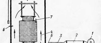
The nature of the daily load is equivalent to the ambient temperature, the time constant of the transformer, the type of cooling, periodic overloads are allowed.
Figure 1—Calculated load graph. 1 – daily allowance in fact; 2 – two-stage equivalent to actual
According to the graph, the initial load period is characterized by the operation of the transformer with a rated load for 20 hours and an initial load factor of 0.705.
The second period is the overload coefficient kper.= 1.27 and the time is 4 hours. This means that overloads are determined by the load graph converted into an equivalent graph taking into account heat. The permissible load of the trolley depends on the rated load, its duration and maximum peak, determined by the load excess factor:
kper = Ie max / Inom
initial load factor
kn.n. = Ie.n./ Inom
Iе max – equivalent maximum load;
Ie.n - equivalent initial load.
Transformer overloads are permissible, but their capabilities: time and magnitude are limited by the standards established by the manufacturer. PTEEP Rules, Chapter 2. 1. 20 and Chapter. 2. 1. 21. limit transformer overload to 5%.
Table No. 4 - Time overload for oil transformers
| Overload value, % | 30 | 45 | 60 | 75 | 100 |
| Duration, min. | 120 | 80 | 45 | 20 | 10 |
Table No. 5 - Time overload for a dry transformer
| Overload value, % | 20 | 30 | 40 | 50 | 60 |
| Duration, min. | 60 | 45 | 32 | 18 | 5 |
The ventilation of the electrical installation room must ensure heat removal so that in case of overload and maximum air temperature, the heating of the transformer does not exceed the permissible value. Often, in hot conditions, in fields remote from populated areas, they resort to natural ventilation by opening the doors of the transformer compartment.
The PUE rules allow a maximum post-emergency overload of a transformer of up to 40% for a period of no more than 6 hours within 5 days.
Standard power scale for power transformers
Our country has adopted a unified scale of transformer power. The choice of a rational scale is one of the main tasks when optimizing industrial power supply systems. Today there are two power scales: in increments of 1.35 and in increments of 1.6. That is, the first scale includes powers: 100, 135, 180, 240, 320, 420, 560 kVA, etc., and the second includes 100, 160, 250, 400, 630, 1000 kVA, etc. Transformers of the first power scale are currently not produced and are used on existing transformer substations, and for the design of new transformer substations the second power scale is used.
It should be noted that a scale with a coefficient of 1.35 is more profitable from the point of view of loading transformers. For example, when operating two transformers with a load factor of 0.7, when one of them is turned off, the second one is overloaded by 30%. This mode of operation meets the requirements of the operating conditions of the transformer. In this way, its power can be fully utilized.
With a permissible overload of 40%, there is an underutilization of the installed power of transformers with a scale of 1.6.
Let’s say two transformers at a transformer substation operate separately and the load of each is 80 kVA; when one of them is turned off, the second one needs to provide a load of 160 kVA. The option of installing two 100 kVA transformers cannot be accepted, since in this case the overload will be 60% when one transformer is taken out of service. When installing 160 kVA transformers, their load in normal mode is only 50%.
When using a scale with a step of 1.35, you can install transformers with a capacity of 135 kVA, then their load in normal mode will be 70%, and in emergency overload will be no more than 40%.
Based on this example, it can be seen that a scale with a step of 1.35 is more rational. And about 20% of the power of manufactured transformers is not used. A possible solution to this problem is to install two transformers at transformer stations of different power. However, this solution cannot be considered technically rational, since if a transformer of higher power fails, the remaining transformer will not cover the entire load of the workshop.
A logical question arises: what caused the transition to a new range of capacities? The answer, apparently, lies in reducing the variety of capacities to unify equipment: not only transformers, but also those adjacent to it (switches, load switches, disconnectors, etc.).
Based on all that has been said, the choice of the number and power of transformers to power factory substations is made as follows :
1) the number of transformers at the transformer substations is determined based on ensuring the reliability of power supply, taking into account the category of receivers;
2) the closest power options for the selected transformers (no more than three) are selected, taking into account their permissible load in normal mode and permissible overload in emergency mode;
3) an economically feasible solution is determined from the identified options, acceptable for specific conditions;
4) the possibility of expanding or developing the transformer substation is taken into account and the issue of the possible installation of more powerful transformers on the same foundations is resolved, or the possibility of expanding the substation by increasing the number of transformers is envisaged.
Short circuits. Basic concepts and relationships between current values.
Short circuit (SC) is an electrical connection of two points of an electrical circuit with different potential values, which is not provided for by the design of the device and disrupts its normal operation. A short circuit can occur as a result of a violation of the insulation of current-carrying elements or mechanical contact of non-insulated elements. A short circuit is also a condition when the load resistance is less than the internal resistance of the power source.
In three-phase electrical networks, the following types of short circuits are distinguished:
single-phase (phase short circuit to ground or neutral wire); two-phase (short circuit of two phases with each other);
two-phase to ground (two phases to each other and simultaneously to ground); three-phase (three phases together)
Short circuits are possible in electrical machines:
interturn - closure of turns of rotor or stator windings, or turns of transformer windings;
short circuit of the winding to the metal body.
Consequences of a short circuit
Railway military equipment - contact network short-circuiting and tapping device (ZOKS)
During a short circuit, the current flowing in the circuit sharply and many times increases, which, according to the Joule-Lenz law, leads to significant heat generation and, as a consequence, melting of electrical wires, followed by the occurrence of fire and the spread of fire.
A short circuit in one of the elements of the energy system can disrupt its functioning as a whole - the supply voltage for other consumers may decrease, which can lead to damage to the device; In three-phase networks, during short circuits, voltage asymmetry occurs, disrupting the normal power supply. In large power grids, a short circuit can cause severe system failures.
If the wires of overhead power lines are damaged and shorted to ground, a strong electromagnetic field may arise in the surrounding space, which can induce an EMF in nearby equipment that is dangerous for the equipment and people working with it.
Protection methods
To protect against short circuits, special measures are taken:
Short circuit current limiting: install current limiting electrical reactors;
parallelization of electrical circuits is used, that is, disconnection of sectional and busbar switches;
use step-down transformers with a split low-voltage winding;
use disconnecting equipment - high-speed switching devices with a short-circuit current limiting function - fuses and circuit breakers;
Relay protection devices are used to disconnect damaged sections of the circuit
Basic concepts and relationships between current values. Electric current is the directionally ordered movement of electric charges. The direction of current is taken to be the direction of movement of positive charges.
The passage of current through a conductor is accompanied by the following actions:
magnetic (observed in all conductors)
thermal (observed in all conductors except superconductors) chemical (observed in electrolytes).
For the occurrence and maintenance of current in any medium, two conditions must be met: 1) the presence of free electric charges in the medium; 1) creation of an electric field in the medium.
In different environments, the carriers of electric current are different charged particles.
An electric field in a medium is necessary to create directional movement of free charges. As is known, a charge q in an electric field of intensity E is acted upon by a force F = q* E, which causes free charges to move in the direction of the electric field. A sign of the existence of an electric field in a conductor is the presence of a non-zero potential difference between any two points of the conductor,
However, electrical forces cannot maintain an electric current for a long time. The directed movement of electric charges after some time leads to equalization of potentials at the ends of the conductor and, consequently, to the disappearance of the electric field in it.
To maintain current in an electrical circuit, charges must be subject to forces of a non-electrical nature (external forces) in addition to Coulomb forces.
A device that creates external forces, maintains a potential difference in a circuit and converts various types of energy into electrical energy is called a current source.
For the existence of electric current in a closed circuit, it is necessary to include a current source in it.
Selecting a power transformer based on rated power.
To select, use the requirements of regulatory documents
Table No. 6 - Dependences of the permissible overload factors of oil transformers for one, two and three transformer substations and the load factor in normal operation
| Permissible overload coefficient of an oil transformer, determined according to GOST 14209-85 | Oil transformer load factor in normal mode | |
| two-transformer substation | three-transformer substation | |
| 1,0 | 0,5 | 0,666 |
| 1,1 | 0,55 | 0,735 |
| 1,2 | 0,6 | 0,8 |
| 1,3 | 0,65 | 0,86 |
| 1,4 | 0,7 | 0,93 |
The manufacturer of electrical equipment, when offering a transformer to the buyer, provides information about permitted overloads.
According to the standards SN 174-75 “Instructions for the design of power supply for industrial enterprises”, different load factors are accepted for each facility:
- Two-transformer substation for load category I - 0.65 to 0.7.
- Substation with one transformer with redundancy for load category II - from 0.7 to 0.8.
- For load categories II and III using reserve – 0.9-0.95.
Thus, we can conclude that the normal mode of the transformer is 90 or even 95% loaded.
The choice of a transformer based on design power consists of comparing the total power of the facility (kVA) and the permissible load intervals of the transformers for various types of consumers in emergency and normal operating modes. They are guided by the methodology for selecting the power of a power transformer and regulatory documents.
Table 1. Technical data of oil-fired two-winding general purpose transformers of 6-10 kV classTransformer type
| Connection diagram exchange | Losses, W | Ukz, % | Iхх, % | Resistance, mOhm | |||||
| xx | short circuit | RT | Ht | Zt | Zt(1) | ||||
| 1 | 2 | 3 | 4 | 5 | 6 | 7 | 8 | 9 | 10 |
| TM-25/10/0.4 | YY-0 | 130 | 600 | 4,5 | 3,2 | 154 | 244 | 287 | 3110 |
| -40 | 175 | 880 | 4,5 | 3 | 88 | 157 | 180 | 1944 | |
| -63 | 240 | 1280 | 4,5 | 2,8 | 52 | 102 | 114 | 1237 | |
| -100 | 330 | 1970 | 4,5 | 2,6 | 31,5 | 65 | 72 | 779 | |
| -160 | 510 | 2650 | 4,5 | 2,4 | 16,6 | 41,7 | 45 | 486 | |
| -250 | 740 | 3700 | 4,5 | 2,3 | 9,4 | 27,2 | 28,7 | 311 | |
| -400 | 950 | 5500 | 4,5 | 2,1 | 5,5 | 17,1 | 18 | 195 | |
| -630 | 1310 | 7600 | 5,5 | 2 | 3,1 | 13,6 | 14 | 128 | |
| -1000 | 2000 | 12200 | 6,5 | 1,4 | 1,7 | 8,6 | 8,8 | 81 | |
| -1600/6/0,4 | 2750 | 18000 | 6,5 | 1,3 | 1,0 | 5,4 | 5,5 | 63,5 | |
| TM-2500/6/0.4 | 3850 | 23500 | 6,5 | 1 | 0,64 | 3,46 | 3,52 | 10,56 | |
| Modernized | |||||||||
| TM-400/10/0.4 | YY-0 | 900 | 5500 | 4,5 | 1,5 | 5,5 | 17,1 | 18 | 81 |
| -630 | 1250 | 7600 | 5,5 | 1,25 | 3,1 | 13,6 | 14 | 63,5 | |
| 1000 | 1900 | 10500 | 5,5 | 1,15 | 1,7 | 8,6 | 8,8 | 26,4 | |
Notes.
- The resistance values indicated in the table are based on a voltage of 0.4 kV.
For transformers with a secondary voltage of 0.23 kV, the table data should be reduced by 3 times, and for 0.69 kV - increased by 3 times.
- Columns 7, 8, 9 indicate positive sequence resistance (for calculating short-circuit currents).
Table 2. Technical data of oil and dry transformers for complete transformer substations
| Transformer type | Connection diagram exchange | Losses, W | Ukz, % | Iхх, % | Resistance, mOhm | ||||
| xx | short circuit | RT | Ht | Zt | Zt(1) | ||||
| 1 | 2 | 3 | 4 | 5 | 6 | 7 | 8 | 9 | 10 |
| TMZ-25/10/0.4 | YY-0 | 740 | 3700 | 4,5 | 2,3 | 9,4 | 27,2 | 28,7 | 311 |
| -400 | 950 | 5500 | 4,5 | 2,1 | 5,5 | 17,1 | 18 | 195 | |
| TMZ (TNZ)-630 | 1310 | 7600 | 5,5 | 1,8 | 3,1 | 13,6 | 14 | 128 | |
| -1000 | 1900 | 10800 | 5,5 | 1,2 | 1,7 | 8,6 | 8,8 | 81 | |
| -1600 | 2650 | 16500 | 6 | 1 | 1 | 5,4 | 5,5 | 63,5 | |
| -2500 | 3750 | 24000 | 6 | 0,8 | 0,64 | 3,46 | 3,52 | 10,56 | |
| TSZ-160 | 700 | 2700 | 5,5 | 4 | 16,6 | 41,7 | 45 | 486 | |
| -250 | 1000 | 3800 | 5,5 | 3,5 | 9,4 | 27,2 | 28,7 | 311 | |
| -400 | 1300 | 5400 | 5,5 | 1,8 | 5,5 | 17,1 | 18 | 195 | |
| TSZL-630 | 2000 | 7300 | 5,5 | 1,5 | 3,1 | 13,6 | 14 | 128 | |
| -1000 | 2500 | 12000 | 8 | 1,1 | 1,7 | 8,6 | 8,8 | 81 | |
| -1600 | 3400 | 16000 | 5,5 | 0,7 | 1 | 5,4 | 5,5 | 63,5 | |
| -2500 | 4600 | 20500 | 6 | 0,65 | 0,64 | 3,46 | 3,52 | 10,56 | |
Note.
Rt, Xt, Zt – active, inductive and impedance of a positive sequence transformer, intended for calculating short-circuit currents.
Zt(1) – current resistance of a single-phase short circuit
Table 3. Technical data of dry-type transformers of general purpose 10 kV class
| Type | Sn, kVA | Rated voltage of windings, V | Losses, W | Ukz, % | Iхх, % | ||
| VN | NN | XX | short circuit | ||||
| 1 | 2 | 3 | 4 | 5 | 6 | 7 | 8 |
| TS-10/0.66 TSZ-10/0.66 | 10 | 380,660 380 | 230, 400 36,42 | 75 (90) | 280 | 4,5 | 7 |
| TS-16/0.66 TSZ-16/0.66 | 16 | 380, 660 220 380 | 230, 400 230 36, 42 | 100(125) | 400 | 4,5 | 5,8 |
| TS-25/0.66 TSZ-25/0.66 | 25 | 380, 660 220 380 | 230, 400 230 36, 42 | 140(180) | 560 | 4,5 | 4,8 |
| TS-40/0.66 TSZ-40/0.66 | 40 | 380, 660 220 380 | 230, 4000 230 36, 42 | 200(250) | 800 | 4,5 | 4 |
| TS-63/0.66 TSZ-63/0.66 | 63 | 380, 660 220 | 230, 4000 230 | 280(350) | 1050 | 4,5 | 3,3 |
| TS-100/0.66 TSZ-100/0.66 | 100 | 380, 660 | 230, 400 | 390(490) | 1450 | 4,5 | 2,7 |
| TS-1600/0.66 TSZ-1600/0.66 | 160 | 380, 660 | 230, 400 | 560(700) | 2000 | 4,5 | 2,3 |
Note.
The data for transformers so-called TSZ is indicated in parentheses.