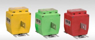
To understand for what operating conditions a particular current or voltage transformer, as well as other types, is intended, special markings of devices are used. Domestic and imported units have different designations. In our country, installations manufactured in accordance with GOST are more often used.
Transformers are marked on a metal shield on the housing. The most common types of transformer symbols will be discussed below.
Information on the case
The information presented on the visible side of the device is applied using engraving, etching or embossing. This ensures the clarity and durability of the inscription. The metal plate contains information about the equipment manufacturer. The year of its manufacture and serial number are applied.
In addition to information about the manufacturer, there must be information about the unit. The number of the standard to which the presented design corresponds is indicated. The rated power indicator must be indicated. For three-phase devices, this parameter is given for each winding separately. Information about the voltage of the coil turns branches is indicated.
The rated current is determined for all windings. The number of installation phases and current frequency are given. The manufacturer provides data on the configuration and connection groups of the coils.
After the above information, you can familiarize yourself with the short circuit voltage parameters. Installation requirements are provided. It can be external or internal.
Technical characteristics allow you to determine the cooling method, the mass of oil in the tank (if this system is used), as well as the mass of the active part. The switch actuator indicates its position. If the installation has a dry type of cooling, there is data on the power of the installation when the fan is turned off.
The serial number must be stamped under the shield. It is present on the tank. The number is indicated on the cover near the HV input, as well as on the top and left on the core beam flange.
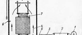
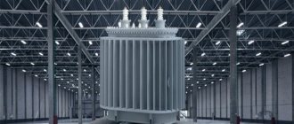
Transformer design TDN
- 1. Expander;
- 2. Input of HV neutral;
- 3. HV input;
- 4. LV input;
- 5. Pipe for gas removal from current transformer installations;
- 7. Bracket for strapping when lifting the transformer;
- 8. Bottom (bottom of the tank);
- 9. Transformer plate;
- 10. Manometric thermometer (signaling);
- 12. Transformer tank;
- 13. Rotary disc valve DN 80 for draining oil from the tank;
- 15. Plug for draining remaining oil from the tank;
- 18. Safety valve;
- 19. Oil sampling valve;
- 21. Hatch for inspection of the on-load tap-changer;
- 25. Stairs;
- 33. Valve DN 25 for adding oil to the conservator of the on-load tap-changer;
- 35. On-load tap-changer protective relay.
The transformer includes the following components: core, windings, main insulation, taps, voltage regulation device, tank, cooling system, protective devices, bushings. The core of the transformer consists of vertical rods covered at the top and bottom with yokes, forming a closed three-phase magnetic circuit. The lamination of the magnetic system plates is carried out according to the scheme with a full oblique joint on the outer rods and a combined joint on the middle rod. The rods are tied using pressing plates and one-piece bandages made of glass tape, yokes - with yoke beams and metal half-bandages. The windings are cylindrical, made of rectangular wire of the APB brand and are located concentrically on the core rod in the following order, counting from the rod: NN, VN, RO.
Scheme
All data shown on the plate can be divided into 6 groups. In order not to get confused in the information, you should consider the sequence of its writing. For example, installation ATDTsTN-125000/220/110/10-U 1. The following groups are used to mark the features of the device:
- Group I. A - Designed to indicate the type of device (power or autotransformer).
- Group II. T - Corresponds to the type of network for which the device is used (single-phase, three-phase).
- III group. DC – Cooling system with forced circulation of oil and air.
- IV group. T – Shows the number of windings (three-winding).
- V group. N – Voltage is regulated under load.
- VI group. All numbers (rated power, voltage of HV MV windings, climatic version, placement category).
You should learn more about each category. This will make the choice much easier.
DECODING OF THE NAMES OF CURRENT TRANSFORMERS
The following abbreviations are used for current transformers:
Table 4 - Decoding of alphabetic and digital designations of the name of the current transformer
Note:
For the series TV, TVT, TVS, TVU;
For the TNP, TNPSh series - with alternating current magnetization;
For the TShV, TVG series;
For TVVG - 24 - water cooling;
For the TNP, TNPSh series;
For the TV, TVT, TVS, TVU series - the rated voltage of the equipment;
For the TNP, TNPSh series - the number of cable cores to be wrapped around;
For the TNP, TNPSh series - rated voltage.
Varieties
The designation of transformers necessarily begins with the type of equipment. If the marking begins with the letter A, it is an autotransformer. Its absence indicates that the unit belongs to the class of power transformers.
The number of phases is required. This allows you to choose an installation operating from a household or industrial network. If the transformer is connected to a three-phase network, the marking will contain a T. Single-phase varieties have the letter O. They are used in household networks.
If the device has a split winding, it will have a P. If there is on-load voltage regulation (OLTC), the device will be marked H on the metal plate. If it is absent, we can conclude that the presented feature is absent in the device.
GENERAL RECOMMENDATIONS
The nomenclature of transformers (decoding the alphabetic and digital designations of the name) is not regulated by any regulatory documents, but is entirely determined by the equipment manufacturer. Therefore, if the name of your transformer cannot be deciphered, then contact its manufacturer or look at the product data sheet. The following explanations of the letters and numbers of the names of transformers are relevant for domestic products.
The name of the transformer consists of letters and numbers, each of which has its own meaning. When deciphering the name, it should be taken into account that some of them may be absent from it altogether (for example, the letter “A” in the name of a regular transformer), while others are mutually exclusive (for example, the letters “O” and “T”).
Special designations
Depending on the installation category, special symbols may apply. For a current and voltage transformer, they may not be the same. The second type of technique is used when operating protective mechanisms or for measuring current. The first category of devices is intended to change the value of alternating current.
Voltage transformers do not use high power transmission of electricity. They are capable of creating isolation from low-voltage communications. This category of devices is used in circuits with a voltage of 12V or less. Their main operating parameters are the current and voltage of the primary winding. It is their value that is provided by the manufacturer.
The marking of voltage transformers begins with their design. If this is a walk-through structure, it is designated by the letter P. If it is not there, this is a supporting type of apparatus. The cast insulator is marked L, and the porcelain insulator is marked F. The built-in insulator is marked V.
Decoding of modern current transformers is carried out in the established sequence. It begins with T, which characterizes the devices presented. The installation method can be through-type (P), support (O) or busbar (W). If this device is present in the equipment of power transformers, it is designated as VT. If it is built into the oil switch, then the marking will have the letter B. When installed externally, the device will have an H.
DECODING OF THE NAMES OF VOLTAGE TRANSFORMERS
The following abbreviations are used for voltage transformers:
Table 3 - Decoding of alphabetic and digital designations of the name of the voltage transformer
Note:
Accessory for the NOSC series;
With compensation winding for NTMK series;
In addition to the NOL and ZNOL series, in which:
— 06 — for installation in closed conductors, indoor switchgear and switchgear;
— 08 — for indoor and outdoor indoor and outdoor switchgear and switchgear;
— 11 — for explosive switchgear.
Cooling system
The transformer symbol continues with the cooling method. Today, there are dry, oil-based varieties. Also, the cooling unit may contain a non-flammable fluid dielectric.
Oil varieties include about a dozen different equipment designs. If the circulation of liquid inside is carried out naturally, the device has an M on the panel. If it is forced, the designation D will be present here. It also corresponds to dry varieties of devices with an internal circulation device presented.
If equipment with natural oil movement and forced water flow is installed, it is marked with the combination MV. For devices with forced circulation of non-directional oil flow and natural air movement, a combination of MCs is used. If in such a device the direction of the oil is clearly indicated, the marking will be NMC.
For systems with forced non-directional movement of oil and air, the designation DC is used, and for directional movement - NDC. When the oil moves in the space between the pipes and partitions through which water flows, such a unit has the letter C on the shield. If the oil flows along a directed vector, the device is marked NC.
Cooling system with liquid dielectric
Today, new types of devices with various improved cooling systems are being put into operation. One of them is equipment with a non-flammable liquid dielectric. If cooling occurs through natural circulation, the presented installation is designated by the letter N. If there is forced air movement, the marking will be ND.
On the plate of units with a directed flow of liquid dielectric and forced air circulation, the NND is indicated. This allows you to choose the right type of equipment.
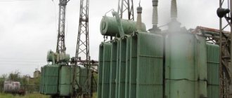
Auxiliary transformer (MV)
An auxiliary transformer is a power equipment that serves to provide the substation with an operational current of 110 V. A device of this type is installed by descending from a 10 kilovolt bus bridge. Power equipment is used by an indicator of operation of automation and protection.
To reduce losses, TM-63 models are installed at substations, and in rare cases TM-160. Read the device of TM and TMG in this article.
The purpose of TSN requires constant operation of the equipment. Therefore, an automatic transfer system (ATS) is also connected, which allows you to transfer power from one substation to another. Traction batteries are used as a backup element.
Dry systems
One of the new varieties is dry cooling systems. They are easy to operate and maintain, not demanding and not capricious. If the installation is open and air circulation occurs naturally, it is marked as C.
The protected version is designated by the letters SZ. The housing can be closed from the influence of various environmental factors; it is called hermetically sealed. With natural air circulation in it, the marking has the letters SG.
Air cooling systems may have forced circulation. In this case, the device is designated by the letters SD.
general characteristics
Split-winding transformers are transformers with a winding divided into 2 or more galvanically unconnected elements.
Such transformers are usually installed at large substations of regional electrical networks and power plants, as well as power supply systems of industrial enterprises. This allows you to connect two or more generators (or independent loads) of the same or different voltage classes to one transformer.
Figure 1.1 shows the designation of a transformer with a split winding in the diagram.
Figure 1.1 – Designation on the diagram
When there is a short circuit in the circuit of one of the parts of the split winding, voltages and currents appear in the other windings of the transformer that are significantly lower than in the same transformer with an unsplit low voltage winding. Such a transformer, with sufficient accuracy for practice, can be considered as 2 independent two-winding transformers, powered from the general network.
Execution
Installations may differ from each other in their design features. If they have forced water circulation, the letter B on the body will make it clear. If there is protection against thunderstorms and lightning, the design is marked G.
The system may have natural circulation of oil or non-flammable dielectric. At the same time, in some varieties protection with a nitrogen cushion is used. It does not have expanders or leads in the flanges of the tank walls. The designation has the letter Z.
Cast insulation is designated as L. The suspended version is designated by the letter P. The improved category of devices is designated as U. They may have automatic on-load tap-changers.
Equipment with leads and an expander installed on the flanges of the tank walls is marked with the letter F. An energy-saving device has reduced energy losses at idle. It is designated by the letter E.
Output for repair
The power transformer TRDN 110/35/10 kV is taken out for repair using operational switching forms. The latter are developed based on the primary connection diagram and the switching devices used. To carry out this task you will need:
- To remove it for repair, the load on the 10 and 35 kilovolt side is removed.
- Disconnection of the 110 kV side is carried out through a short circuit-isolator connection or using SF6 circuit breakers.
- The output of overlays and automation is carried out on the basis of a relay circuit. The TSN load is transferred. According to the mode, ZON-110 kV is turned on.
Grounding is carried out on each side from which voltage can be supplied. The grounding blades on the switch or on the transformer disconnector RLNDz-110 are turned on, the circuit breaker on the 35 kV MV is turned on, and portable grounding is installed on the 10 kV bus bridge.
Purpose
After the category of performance features, information about the purpose and scope of the equipment is presented. Marking with the letter B indicates the ability of the structure to warm up the soil or concrete in winter. A transformer intended for drilling rigs may have the same designation.
When electrifying the railway, installations with special properties and characteristics are needed. They are marked with the letter Z. Devices with the designation M are used at metallurgical plants.
When transmitting direct current through a line, class P structures are needed. Units for ensuring the operation of submersible pumps are designated as PN.
If the unit is used for the power plant’s own needs, it belongs to category C. Type TO is used for processing soil and concrete at high temperatures, providing electricity for temporary lighting and hand tools.
In coal mines transformers of the Sh variety are used, and in the electrical power supply system of an excavator - E.
Technical characteristics of the power transformer TDN, TRDN, TRDTSN:
| Type | Rated voltage of windings, kV | Winding connection diagram and group | Type, range and number of voltage regulation stages | Type of cooling | Weight, T | Dimensions length x width x height, mm installation transport | ||||
| VN | NN | full | oils | oil for topping up | transport | |||||
| TDN-10000/110-U1 | 115 | 6,6; 10,5;11,0 | Yn/Δ-11 | On-load tap-changer in neutral HV =16%, =9 stages | D | 35,62 | 11,8 | 2,2 | 31 | 5385x3320x4250 5220x2050x2820 |
| TDN-16000/110-U1 | 115 | 6,3; 6,6; 11,0;34,5 | Yn/Δ-11 | D | 40,31 | 12,57 | 2,47 | 36 | 5510x3500x5160 5150x2075x4051 | |
| TDN-25000/110-U1 | 115 | 11,0 | Yn/Δ-11 | D | 52 | 15 | 4,1 | 45 | 5710x4860x5355 5570x2210x4000 | |
| TRDN-25000/110-U1 | 115 | 6,3-6,3;10,5-10,5;10,5-6,3 | Yн/Δ-Δ-11-11 | D | 52,0 | 15,38 | 3,2 | 47,5 | 5710x4860x5335 5400x1940x 3940 | |
| TRDN-32000/110-U1 | 115 | 6,3-6,3 | Yн/Δ-Δ-11-11 | D | 66,0 | 16,5 | 3,61 | 54 | 6685x4580x6090 6100x2100x3720 | |
| TDN-40000/110-U1 | 115 | 36,5;10,5 | Yi/Δ-11 | D | 66,7 | 16,6 | 4,3 | 55,5 | 6250x4680x5680 5278x2104x4434 | |
| TRDN-40000/110-U1 | 115 | 6,3-6,3;10,5-10,5;10,5-6,3;6,9-6,9 | Yн/Δ-Δ-11-11 | D | 66,7 | 16,6 | 4,23 | 58 | 6250x4680x5860 5160x2130x4370 | |
| TRDN-63000/110-U1 | 115 | 6,3-6,3;6,6-6,6;10,5-10,5;10,5-6,3;11,0-11,0 | Yi/Δ-Δ-11-11 | D | 77,94 | 16,7 | 3,65 | 74,5 | 7200x4700x6100 5570x2260x4460 | |
| TRDCN-63000/110-U1 | 115 | 6,3-6,3;6,6-6,6;10,5-10,5;10,5-6,3;11,0-11,0 | Yi/Δ-Δ-11-11 | DC | 73,8 | 15,57 | 2,52 | 74,5 | 7200x4550x6100 5570x2260x4460 | |
| TDNM-63000/ 100000/ 110-U1 | 115 | 10,5; 38,5 | Yn/Δ-11 | D | 86,8 | 20 | 5,1 | 74,5 | 6700x5100x6200 5570x2260x4460 | |
| TRDN-80000/110-U1 | 115 | 6,3-6,3;6,6-6,6;10,5-10,5;10,5-6,3;11,0-11,0 | Yн/Δ-Δ-11-11 | D | 104 | 23 | 8,1 | 92 | 6680x5220x6720 5850x2460x4485 | |
| TRDN-80000/110-U1 | 121 | 10,5-10,5 | Yн/Δ-Δ-11-11 | D | 104 | 23 | 8,1 | 92 | 6680x5220x6720 5850x2460x4485 | |
| TRDCN-80000/110-U1 | 115 | 6,3-6,3;6,6-6,6;10,5-10,5;10,5-6,3;11,0-11,0 | Yн/Δ-Δ-11-11 | DC | 122 | 31,55 | 4,5 | 106,5 | 6920x4628x6835 5850x2460x4485 | |
Characteristics of the TSL transformer
Numbers
The listed designations may be followed by numerical values. This is the rated winding voltage in kV, power in kVA. For autotransformers, information about the voltage of the MV winding is added.
The marking may contain the first year of manufacture of the presented design. The power of the units can be 20.40, 63, 160, 630, 1600 kVA, etc. This indicator is selected in accordance with the operating conditions. Higher power equipment is available. This parameter can reach 200, 500 MVA.
The duration of use of Soviet-made transformers is about 50 years. Therefore, modern energy communications can use equipment manufactured before 1968. They are periodically improved and reconstructed during major overhauls.
EXAMPLES OF CODING THE NAMES OF VOLTAGE TRANSFORMERS
NOSK-3-U5 - single-phase voltage transformer with dry insulation, component, rated voltage of the HV winding 3 kV, climatic version - U5;
NOM-15-77U1 - single-phase voltage transformer with oil insulation, rated voltage of the HV winding 15 kV, developed in 1977, climatic version - U1;
ZNOM-15-63U2 - voltage transformer with a grounded end of the high-voltage winding, single-phase with oil insulation, rated voltage of the high-voltage winding 15 kV, developed in 1963, climatic version - U2;
ZNOL-06-6U3 - voltage transformer with a grounded end of the high-voltage winding, single-phase with cast epoxy insulation, for installation in closed conductors, indoor switchgear and switchgear, climatic version - U3;
NTS-05-UHL4 - three-phase voltage transformer with dry insulation, rated voltage of the HV winding 0.5 kV, climatic version - UHL4;
NTMK-10-71U3 - three-phase voltage transformer with oil insulation and compensation winding, rated voltage of the HV winding 10 kV, developed in 1971, climatic version - U3;
NTMI-10-66U3 - three-phase voltage transformer with oil insulation and a winding for monitoring network insulation, rated voltage of the HV winding 10 kV, developed in 1966, climatic version - U3;
NKF-110-58U1 - cascade voltage transformer in a porcelain cover, rated voltage of the HV winding 110 kV, developed in 1958, climatic version - U1;
NDE-500-72U1 - voltage transformer with a capacitive divider, rated voltage of the HV winding 500 kV, developed in 1972, climatic version - U1;
Examples
To understand how to interpret the information on the equipment body, you should consider several examples of markings. These can be the following transformers:
- TDTN-1600/110. Three-phase class of step-down type equipment. It has oil forced cooling and an on-load tap-changer. The rated power is 1600, and the HV winding voltage is 110 kV.
- ATDTsTN-120000/500/110-85. Autotransformer, which is used in a three-phase network. It has three windings. The oil cooling system has forced circulation. There is an on-load tap-changer. The rated power is 120 MVA. The device reduces voltage and operates between 500 and 110 kV networks. Developed in 1985.
- TM-100/10 is a two-winding unit that is designed to operate in a three-phase network. The oil circulation system has natural fluid movement. The voltage change occurs using the PBB unit. The rated power is 100 kVA, and the winding class is 10 kV.
- TRDNS-25000/35-80. Device for a three-phase network with two split windings. Cooling is carried out through forced oil circulation. The design includes an on-load tap-changer regulator. Used for the needs of power plants. The power of the unit is 25 MVA. Winding voltage class – 35 kV. The design was developed in 1980.
- OTs-350000/500. Two-winding device for a single-phase upgrading network. Oil cooling is used using forced fluid movement. Power 350 MVA, winding voltage 500 kV.
- TSZ-250/10-79. An instance for a three-phase network with a dry cooling method. The case is protected. The power is 250 kVA, and the windings are 10 kV. The device was created in 1979.
- TDTSTGA-350000/500/110-60. Three-winding device for three-phase network. Used to increase voltage. Transformation occurs according to the principle of NN-CH and NN-VN. The design was developed in 1960.
All about energy
The name (or rather, nomenclature) of the transformer speaks about its design features and parameters. If you know how to read the name of the equipment, you can only find out the number of windings and phases of the power transformer, type of cooling, rated power and voltage of the highest winding.
General recommendations
The nomenclature of transformers (decoding the alphabetic and digital designations of the name) is not regulated by any regulatory documents, but is entirely determined by the equipment manufacturer. Therefore, if the name of your transformer cannot be deciphered, then contact its manufacturer or look at the product data sheet. The following explanations of the letters and numbers of the names of transformers are relevant for domestic products.
The name of the transformer consists of letters and numbers, each of which has its own meaning. When deciphering the name, it should be taken into account that some of them may be absent from it altogether (for example, the letter “A” in the name of a regular transformer), while others are mutually exclusive (for example, the letters “O” and “T”).
Explanation of the names of power transformers
The following letter designations are accepted for power transformers [1, p.238]:
Table 1 - Explanation of letter and digital designations for the name of the power transformer
| 1. Autotransformer | A |
| 2. Number of phases | |
| Single phase | ABOUT |
| Three-phase | T |
| 3. With split winding | R |
| 4. Cooling | |
| Dry transformers: | |
| natural airy when open | WITH |
| natural air with protected design | NW |
| natural air with sealed design | SG |
| air with forced air circulation | SD |
| Oil transformers: | |
| natural circulation of air and oil | M |
| forced air circulation and natural oil circulation | D |
| natural air circulation and forced oil circulation with non-directional oil flow | MC |
| natural air circulation and forced oil circulation with directed oil flow | NMC |
| forced air and oil circulation with non-directional oil flow | DC |
| forced circulation of air and oil with directed oil flow | NDC |
| forced circulation of water and oil with non-directional oil flow | C |
| forced circulation of water and oil with directed oil flow | NC |
| 5. Three-winding | T |
| 6. Branch switching | |
| on-load regulation (OLTC) | N |
| automatic control under load (ARLP) | AN |
| 7. Cast insulation | L |
| 8. Extender version | |
| with expander | F |
| without expander, with nitrogen blanket protection | Z |
| without expander in a corrugated tank (sealed packaging) | G |
| 9. With balun | U |
| 10. Suspended version (on an overhead line support) | P |
| 11. Purpose | |
| for own needs of power plants | WITH |
| for DC lines | P |
| for metallurgical production | M |
| for powering submersible electric pumps | Mon |
| for heating concrete or soil (concrete heating), for drilling rigs | B |
| for powering electrical equipment of excavators | E |
| for heat treatment of concrete and soil, power supply for hand tools, temporary lighting | THAT |
| mine transformers | Sh |
| Rated power, kVA | [number] |
| HV winding voltage class, kV | [number] |
| Voltage class of the MV winding (for auto- and three-winding tr-s), kV | [number] |
Note
: forced air circulation is called blowing, that is, “with forced air circulation” and “with blowing” are equivalent expressions.
Examples of deciphering the names of power transformers
TM - 100/35
— three-phase oil transformer with natural circulation of air and oil, rated power 0.1 MVA, voltage class 35 kV;
TDNS - 10000/35
- three-phase transformer with oil blowing, adjustable under load for the power plant’s own needs, rated power 10 MVA, voltage class 35 kV;
TRDNF - 25000/110
- three-phase transformer, with split winding, oil with forced air circulation, adjustable under load, with an expander, rated power 25 MVA, voltage class 110 kV;
ATDTsTN - 63000/220/110
- three-phase oil autotransformer with blowing and forced oil circulation, three-winding, adjustable under load, rated power 63 MVA, HV class - 220 kV, MV class - 110 kV;
AODTSTN - 333000/750/330
- single-phase oil autotransformer with blowing and forced oil circulation, three-winding, adjustable under load, rated power 333 MVA, HV class - 750 kV, MV class - 500 kV.
Explanation of the names of regulating (voltage booster) transformers
For control transformers, the following abbreviations are accepted [1, p.238][2, p.150]:
Table 2 - Explanation of alphabetic and digital designations of the name of the control transformer
| 1. Voltage booster transformer | IN |
| 2. Regulating transformer | R |
| 3. Linear adjustment | L |
| 4. Three-phase | T |
| 5. Cooling type: | |
| forced air circulation and natural oil circulation | D |
| natural circulation of air and oil | M |
| 6. Load regulation (OLTC) | N |
| 7. Lateral regulation | P |
| 8. Lightning-resistant design | G |
| 9. With reinforced input | U |
| Passing power, kVA | [number] |
| Excitation winding voltage class, kV | [number] |
| Voltage class of the control winding, kV | [number] |
Examples of deciphering the names of control transformers
VRTDNU - 180000/35/35
— booster transformer, regulating, three-phase, oil-cooled, type D, adjustable under load, with reinforced input, throughput power 180 MVA, rated voltage of the excitation winding 35 kV, rated voltage of the regulating winding 35 kV;
LTMN - 160000/10
- linear transformer, three-phase, with natural circulation of oil and air, adjustable under load, throughput power 160 MVA, rated line voltage 10 kV.
Explanation of the names of voltage transformers
For voltage transformers, the following abbreviations are accepted [2, p.200]:
Table 3 - Explanation of alphabetic and digital designations of the voltage transformer name
| 1. The end of the HV winding is grounded | Z |
| 2. Voltage transformer | N |
| 3. Number of phases: | |
| Single phase | ABOUT |
| Three-phase | T |
| 4. Insulation type: | |
| Dry | WITH |
| Oily | M |
| Cast epoxy | L |
| 5. Cascade (for NKF series)(1,2) | TO |
| 6. In a porcelain cover | F |
| 7. With winding to control network insulation | AND |
| 8. With capacitive divider (NDE series) | DE |
| Rated voltage(3), kV | [number] |
| Climatic performance | [number] |
- Note
- Accessory for the NOSC series;
- With compensation winding for NTMK series;
- In addition to the NOL and ZNOL series, in which:
:
- 06 - for installation in closed conductors, indoor switchgear and switchgear;
- 08 - for indoor and outdoor indoor and outdoor switchgear and switchgear;
- 11 - for explosive switchgear.
Examples of decoding names of voltage transformers
SOCK-3-U5
— single-phase voltage transformer with dry insulation, component, rated voltage of the HV winding 3 kV, climatic version — U5;
NOM-15-77U1
- single-phase voltage transformer with oil insulation, rated voltage of the HV winding 15 kV, developed in 1977, climatic version - U1;
ZNOM-15-63U2
- voltage transformer with a grounded end of the high-voltage winding, single-phase with oil insulation, rated voltage of the high-voltage winding 15 kV, developed in 1963, climatic version - U2;
ZNOL-06-6U3
- voltage transformer with a grounded end of the high-voltage winding, single-phase with cast epoxy insulation, for installation in closed conductors, indoor switchgear and switchgear, climatic version - U3;
NTS-05-UHL4
- three-phase voltage transformer with dry insulation, rated voltage of the HV winding 0.5 kV, climatic version - UHL4;
NTMK-10-71U3
- three-phase voltage transformer with oil insulation and compensation winding, rated voltage of the HV winding 10 kV, developed in 1971, climatic version - U3;
NTMI-10-66U3
- three-phase voltage transformer with oil insulation and winding for monitoring network insulation, rated voltage of the HV winding 10 kV, developed in 1966, climatic version - U3;
NKF-110-58U1
- cascade voltage transformer in a porcelain cover, rated voltage of the HV winding 110 kV, developed in 1958, climatic version - U1;
NDE-500-72U1
- voltage transformer with a capacitive divider, rated voltage of the HV winding 500 kV, developed in 1972, climatic version - U1;
Explanation of the names of current transformers
For current transformers, the following abbreviations are accepted [2, p.201,206-207,213]:
Table 4 - Interpretation of alphabetic and digital designations of the name of the current transformer
| 1. Current transformer | T |
| 2. In porcelain cover | F |
| 3. Type: | |
| Built-in(1) | IN |
| Generator | G |
| Zero sequence | N |
| Single turn | ABOUT |
| Passable(2) | P |
| Reinforced | U |
| Tire | Sh |
| 4. Winding design: | |
| Link type | Z |
| U-type | U |
| Latch type | R |
| 5. Insulation performance: | |
| Cast | L |
| Oily | M |
| 6. Air cooling(3.4) | IN |
| 7. Ground fault protection of individual cable cores(5) | Z |
| 8. Performance category | A, B |
| Rated Voltage(6.7) | [number] |
| Thermal current(8) | [number] |
| Climatic performance | [number] |
- Note
- For the series TV, TVT, TVS, TVU;
- For the TNP, TNPSh series - with alternating current magnetization;
- For the TShV, TVG series;
- For TVVG - 24 - water cooling;
- For the TNP, TNPSh series;
- For the TV, TVT, TVS, TVU series - the rated voltage of the equipment;
- For the TNP, TNPSh series - the number of cable cores to be wrapped around;
- For the TNP, TNPSh series - rated voltage.
:
Examples of deciphering the names of current transformers
TFZM - 35A - U1
— current transformer in a porcelain cover, with a link winding, oil insulated, rated voltage of the HV winding 35 kV, category A, climatic version U1;
TFRM - 750M - U1
- current transformer in a porcelain cover, with a link winding, with oil insulation, rated voltage of the HV winding 750 kV, climatic version U1;
TSHL - 10K
- bus current transformer with cast insulation, rated voltage of the HV winding 10 kV;
TLP - 10K - U3
- current transformer with cast insulation, feed-through, rated voltage of the HV winding 10 kV, climatic version - U3;
TPOL - 10
- feed-through current transformer, single-turn, with cast insulation, rated voltage of the HV winding 10 kV;
TSHV - 15
- busbar current transformer, air-cooled, rated voltage of the HV winding 15 kV;
TVG - 20 - I
- air-cooled current transformer, generator, rated voltage of the HV winding 20 kV;
TShLO - 20
- bus current transformer, with cast insulation, single-turn, rated voltage of the HV winding 20 kV;
TV - 35 - 40U2
- built-in current transformer, rated voltage of the HV winding 35 kV, thermal resistance current 40 kA, climatic version - U2;
TNP - 12
- zero-sequence current transformer, with alternating current bias, covering 12 cable cores;
TNPSh - 2 - 15
- zero-sequence current transformer, with alternating current bias, busbar, covering 2 cable cores, rated voltage of the HV winding 15 kV.
List of sources used
- Handbook for designing electrical networks / ed. D.L. Faibisovich. — 3rd ed., revised. and additional - Moscow: ENAS, 2009. - 392 p.: ill.
- Handbook of High Voltage Electrical Installations / ed. I.A. Baumshteina, S.A. Bazhenova. — 3rd ed., revised. and additional - Moscow: Energoatomizdat, 1989. - 768 p.: ill.
Links and literature
. Rozhkova L.D., Kozulin V.S. Electrical equipment of stations and substations. - M.: Energoatomizdat, 1987. - 315 p. . Neklepaev B.N. Electrical part of power plants and substations. Textbook for universities. 2nd ed. - M.: Energoatomizdat, 1986.-310 p. . Rules for the technical operation of electrical installations. Approved by order of the Ministry of Fuel and Energy of Ukraine dated July 25, 2006. GOST R 52719–2007. Power transformers. General technical conditions. – M.: Standards Publishing House, 2007. – 45 p. . GOST 12.2.007.0–75. System of occupational safety standards. Electrical publication. General safety requirements. – M.: Standards Publishing House, 1975. – 12 p. . GOST 12.2.007.2–75. System of occupational safety standards. Power transformers and electrical reactors. Safety requirements. – M.: Standards Publishing House, 1975. – 5 p.
What is a power transformer and its purpose
This is a device that converts the amplitude of alternating voltage, leaving its frequency unchanged. The operation of such a device is based on the principle of electromagnetic induction. We will not be distracted by its description; all detailed information can be found on the pages of our website.
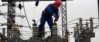
The main scope of application of ST is related to the transmission and distribution of electricity, this is presented in a simplified manner in the figure below.
Electricity transmission scheme
As can be seen from the figure, several CTs can be installed in the circuit between the generator and the consumer. The first increases the voltage to 110 kV (the higher it is, the lower the losses during long-distance transmission) and supplies it to the power line. At the output of the line, a second CT is installed at the regional substation, from where transmission is carried out via an underground cable to the transformer point, from where the end consumers are powered.
Transformer point
Calculation of parameters
Figure 1.2 shows the equivalent circuit of a transformer with a split winding.
Figure 1.2 – Transformer equivalent circuit
Transformers with split winding are made with a winding power ratio equal to 100% / 50% / 50% []. For transformers with a split winding, the individual parameters are: – splitting resistance ZP (equal to the resistance between the terminals of the two branches of the split winding):
since the branches are the same:
– through resistance Zrms = ZV-N, equal to the resistance between the terminals of the high voltage winding and the combined (paralleled) branches of the split low voltage winding;
– coefficient of splitting of the CR is equal to:
The parameters of the equivalent circuit are determined by the following formulas:
To determine Z we use the formulas:
R is determined by the following formulas:
X will be calculated using the formulas:
kT H-B is determined by the formula:
Safety requirements and environmental protection
General technical conditions for power transformers are given in [4]. GOST includes technical requirements, safety requirements, including fire safety requirements, environmental protection requirements, operating instructions, transportation and storage. Safety requirements must also comply with [5, 6]. According to standard [5], transformer tanks are grounded.
The degree of protection of transformers is determined by the standard [6]. It states that all transformers, except built-in ones, must be made with protection class 1 or 2 and have a degree of protection of at least IP20. Stationary transformers, in turn, can be manufactured with a degree of protection IP00. The system of standards [4] provides requirements for transformer disposal. It describes the following series of actions:
- transformer oil should be drained and sent for regeneration;
- metal components of the transformer must be recycled;
- porcelain insulators, electrical cardboard, rubber seals must be sent to a solid waste landfill.
Three-phase and single-phase two-winding transformers 500-750 kV
(without voltage regulation)
Table 5.21
| Type | Snom, MBA | Catalog data | Calculated data (for three phases) | |||||||
| Unom of windings, kV | IR, % | Pk, kW | Рх, kW | Iх, % | RT, Ohm | Xt, Ohm | Qx, kvar | |||
| VN | NN | |||||||||
| TDC-250000/500, TC-250000/500 | 250 | 525 | 15,75 | 13 | 600 . | 250 | 0,45 | 2,65 | 143 | 1125 |
| TDTs-400000/500, TTD-400000/500 | 400 | 525 | 13,8; 15,75; 20 | 13 | 800 | 350 | 0,4 | 1,4 | 89,5 | 1600 |
| TC-630000/500 | 630 | 525 | 15,75; 20; 24 | 14 | 1300 | 500 | 0,35 | 0,9 | 61,3 | 2205 |
| TC-1000000/500 | 1000 | 525 | 24 | 14,5 | 2000 | 600 | 0,38 | 0,55 | 40 | 3800 |
| OTs-533000/500* | 533 | 525/3 | 15,75; 24 | 13,5 | 1400 | 300 | 0,3 | 0,45 | 23,3 | 4797 |
| ORC-417000/750* | 417 | 787/3 | 20; 24 | 14 | 800 | 400 | 0,3 | 0,96 | 69,3 | 3753 |
* The LV winding is made split into two with a power of 50% each.