- home
- Electrical apparatus
- Current transformers: purpose and principle of operation
In today's material, I decided to start considering issues related to the basics of the theory of current transformers.
These devices themselves are ubiquitous in electrical installations, and I think everyone will find it interesting and useful to update their memory on the principle of their operation. Purpose of current transformers: current conversion and circuit separation
Let's start by answering the question - what is a current transformer for? There are several main issues that the installation of current transformers solves.
- Firstly, this is the measurement of large currents, when directly measuring the real value of the primary current is not possible. The value converted downwards after the current transformer is measured. This is usually 1, 5 or 10 amps.
- Secondly, this is the separation of primary and secondary circuits. Thus, the insulation of relay equipment, electricity meters, and measuring instruments is protected.
Explanation of device abbreviations
They also differ in the method of insulation: dry, cast and oil. Each has its own letter designation for the transformer. There are different voltage classes, such as ntmi-10, nom-10, znom-35, nom-35, NKF-110, nami-10. In the previous sentence, the numbers indicate the rated voltage. Let's start with the most important letter, which is at the very beginning of almost all abbreviations, this is the letter N. It just means a voltage transformer. By the way, it is simply called TN for short.
The next letters on the list and in importance are T and O, which indicate the number of phases. Three-phase and single-phase respectively. The letter T has another meaning, it means that the transformer has three windings. The following letters refer to insulation and cooling methods. It can be cast (L), C dry, Natural mental cooling, marked with the letter M.
The following values can be classified as additional functions. To connect measuring instruments, apply (I). If we see (K), we should understand that the voltage transformer has an additional winding that reduces the angular error or cascade. “Z” – presence of a grounding terminal. The active part is often placed in a porcelain cover, which is why the “F” symbol is present. (U) - refers to installations in moderate climates. D, E – divider, has a certain capacity.
Decoding abbreviations.
Transformer types
In accordance with their parameters and characteristics, all types of transformers are divided:
- Depending on the number of phases, they can be single- or three-phase
- In accordance with the number of windings, transformers can be two- or three-winding, as well as two- or three-winding with a split winding
- By type of insulation - dry (C) and oil (M) or with non-flammable filling (N)
- By type of cooling - with natural oil cooling (M), with oil cooling and air blast (D), forced circulation of oil cooling (C), dry air-cooled transformers (C). In addition, there are devices without expanders that use a nitrogen blanket to protect them.
Among the various transformer devices, the most common transformers are:
- power
- measuring
- special
Types and their features
In addition to the step-down and step-up devices discussed above, other models are also available:
- traction;
- laboratory ones, in which it is possible to regulate the voltage;
- for rectifier installations;
- power supplies for radio equipment.
All of them belong to one large group of transformers - power ones. There is another type of such equipment. These are devices used to connect various electrical measuring instruments to high voltage circuits. They are called voltage measuring transformers. These devices are also widely used in electric welding. They also differ in design. Depending on this, two and multi-winding current and voltage measuring transformers are distinguished. Such devices are used for carrying out measurements and powering automation circuits and relay protection. They can be single- or three-phase with oil or air cooling.
It will be interesting➡ What is a transformer substation
The classification and shape of the magnetic circuit also influences. He can be:
- core;
- armored;
- toroidal.
In this case, two types of winding designs are distinguished:
- Concentric;
- Disk.
According to the accuracy class, devices are divided into 4 categories:
- 0,2;
- 0,5;
- 1,0;
Another parameter that influences the specific application of current and voltage measuring transformers is the installation method. Depending on it, products are of the following types:
- internal;
- external;
- for switchgear.
Types of transformers.
Voltage transformer
The range of TN products is very diverse. There are many positions of 5 types of products that differ in their purpose.
Power
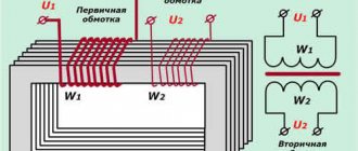
In household appliances, the most widely used type of power devices is those designed to be powered from a 220V 50Hz network. These are classic devices consisting of W1 and one or more W2 windings on an iron core. Depending on the configuration of the magnetic circuit, there are rod, ring and toroidal power transformers.
Measuring
This device is similar in principle to a power device, only it is designed for connecting measuring instruments, protection relays and automation. It allows the use of standard measuring instruments for high voltage measurements without interfering with the structure.
Coordinator
Type CT matches the impedance of the signal source with the impedance of the loaded stage. Products of this type are used to coordinate various components in a wide range of frequencies (LF, microwave).
Laboratory
These devices are used for conducting various experiments, debugging electronic equipment, and are actively used in amateur radio. They represent U step regulators. Unlike LATR, to which it is a worthy alternative, the device has galvanic isolation from the 220V, 50V network.
High voltage
Represents single-phase and three-phase electromagnetic devices in open or molded block design. Typically, the rated power of the device is ≤ 600 kVA, the input U1 does not exceed 20 kV, and the output U2 ≤ 15 kV.
Equipment selection criteria
A voltage transformer consists of two windings and a core. Windings are also divided into primary and secondary. This is where the differences begin when comparing a voltage transformer with a current transformer. The primary winding of a voltage transformer contains significantly more turns than the secondary winding.
A voltage is applied to the primary winding, which we need to measure, and a voltmeter is connected to the secondary winding. Usually, when purchasing equipment, it is not its basic parameters that are taken into account. For a transformer these are:
- winding voltages, which are indicated on the panel;
- transformation ratio;
- angular error.
Interesting material to familiarize yourself with: what you need to know about the design of a power transformer.
It is also necessary to focus on operating conditions. Therefore, the most important parameters when choosing are the load, scope of application and short-circuit voltage of the transformer. At the first stage, it is necessary to make sure that the model’s power will be sufficient to cope not only with the task at hand, but also with possible overloads. It’s a good idea to have a device whose parameters can be changed during operation.
But focusing only on these characteristics is unacceptable. Since for the efficient operation of a 110 kV voltage transformer its technical characteristics are also important:
- current frequency;
- phasicity;
- installation method;
- location;
- load.
In addition, you need to determine whether the price of the device is right for you, as well as the cost of its further maintenance. The parameters for selecting current transformers are given in the table below.
Current transformer selection table.
Design and principle of operation
The manufacturer chooses the basic rules for the operation of the unit, but this does not affect the reliability of operation. The concepts differ in the manufacturing process. The principle of operation of the transformer is based on two provisions:
- the changing movement of directed charge carriers creates an alternating magnetic force field;
- influencing the power flow transmitted through the coil produces electromotive force and induction.
The device consists of the following parts:
- magnetic drive;
- coils or windings;
- basis for the arrangement of turns;
- insulating material;
- cooling system;
- other elements of fastening, access, protection.
The operation of a transformer is carried out according to the type of design and combination of core and windings. In the rod type, the conductor is enclosed in the windings and is difficult to see. The spiral turns are visible, the top and bottom of the core are visible, the axis is located vertically. The material that makes up the coil must conduct electricity well.
In armor-type products, the rod hides most of the turns; it is placed horizontally or vertically. The toroidal design of transformers provides for the location of two independent windings on the magnetic core without electrical connection with each other.
Magnetic system
Made from alloy transformer steel, ferrite, permalloy while maintaining the geometric shape to produce the magnetic field of the unit. The conductor is constructed from plates, tapes, horseshoes, and is made on a press. The part on which the winding is located is called the rod. A yoke is an element without turns that completes the circuit.
The operating principle of the transformer depends on the rack layout, which can be:
- flat - the axes of the yokes and cores are in a single plane;
- spatial - longitudinal elements are arranged in different surfaces;
- symmetrical - conductors of the same shape, size and design are located to all yokes in the same way as others;
- asymmetrical - individual racks differ in appearance, dimensions and are placed in different positions.
If it is assumed that a direct current flows through the winding, which is called the primary winding, then the magnetic wire is made open. In other cases, the core is closed, it serves to close the power lines.
Windings
They are made in the form of a set of turns arranged on square conductors. The shape is used for efficient operation and increasing the fill factor in the magnetic circuit window. If it is necessary to increase the cross-section of the core, then it is made in the form of two parallel elements to reduce the occurrence of eddy currents. Each such conductor is called a core.
The rod is wrapped in paper and coated with enamel varnish. Sometimes two cores arranged in parallel are enclosed in a common insulation, the set is called a cable. Windings are distinguished by purpose:
- the main ones - alternating current is supplied to them, and the converted electric current comes out;
- regulating - they provide taps for voltage transformation at low current;
- auxiliary - serve to supply their network with a power less than the rated value of the transformer and bias the circuit with direct current.
Wrapping methods:
- ordinary winding - turns are made in the direction of the axis along the entire length of the conductor, subsequent turns are wound tightly, without gaps;
- screw wrapping - multi-layer wrapping with gaps between rings or overlap with adjacent elements;
- disc wrapping - a spiral row is performed sequentially, in a circle the wrapping is done in a radial order in the internal and external directions;
- the foil spiral is made from a wide sheet of aluminum and copper, the thickness of which ranges from 0.1-2 mm.
How does it work
After an alternating voltage U1 appears in the primary winding, an alternating magnetic flux Ф appears in the magnetic circuit, which excites voltage in the secondary winding U2. This is the simplest and most concise description of the operating principle of a voltage transformer. The most important parameter of transformers is the “transformation ratio” and is denoted by the Latin “n”. It is calculated by dividing the voltage in the primary winding by the voltage in the secondary winding or the number of turns in the first coil by the number of turns in the second coil.
This coefficient allows you to calculate the required parameters of your transformer for the selected device. For example, if the primary winding has 2000 turns and the secondary winding has 100 turns, then n=20. With a network voltage of 240 volts, the output of the device should be 12 volts. You can also determine the number of turns at given input and output voltages.
Design Features
What are these transformers made of? What is the difference between a current transformer and a voltage transformer? The answers to these questions can be found in the description of the design features. Current transformers, their purpose and principle of operation, imply the constancy of certain conditions:
- every CT must have more than one winding on its magnetic core;
- windings that are secondary are certainly connected to the load (Rн);
- resistance Rн should not contain deviations from the TT stated in the documents;
- The primary winding is made as a busbar passing through the core or in the form of a coil.
What is a diode - operating principle and device
The absence of a load on the secondary winding does not ensure the occurrence of magnetic flux F2 in the core, which has a compensating property. This leads to an increase in the temperature of the core and its melting. Heating occurs because F1 becomes too high.
Resistance deviation Rн affects the measurement error and worsens it. If the resistance in the secondary winding is exceeded, the voltage U2 increases and the CT insulation may fail. A breakdown will occur and the device will fail.
Information. Voltage transformers (VTs) differ from CTs in their method of application and connection diagram. They are connected in parallel and are designed to increase or decrease the voltage, decoupling the power circuit from the control and monitoring circuit. The main operating regulations of the fuel pump are close to the idle mode (idle). This is due to the fact that parallel-connected elements of the control circuit consume low current, and their Rн is large.
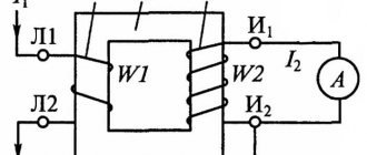
Classic TT device
What is the difference
By definition, these devices are designed to work with different electrical quantities as basic ones and, accordingly, the switching circuits will be different. For example, a current transformer is powered by a current source and does not work, and may even fail, if its windings are not loaded and no electric current flows through them. A voltage transformer is powered by voltage sources and, conversely, cannot operate for a long time at high current loads.
It will be interesting➡ Transformers for LED strips, expert opinion
Features of energy transformation for TT
How it works and how to choose a current transformer
To understand why current transformers are needed, and how they differ from voltage transformers (VT), you can consider their design. The presence of such devices in electrical circuits is associated with the need to transform: lower or increase voltage or current. Alternating electricity generated by generators at power plants is first subjected to transformation before being transmitted through the power grid.
Instrument transformers
When operating equipment with high operating voltages and high current consumption, the question of their measurement and control arises. This is where instrument transformers come to the rescue. They provide galvanic isolation of measuring equipment from circuits with increased danger and reduce the measured value to the level required for measurements.
Before buying a voltage transformer, you need to analyze all the requirements for the device. It is necessary to take into account not only operating voltages, but also load currents when using a transformer in various devices.
You can make voltage transformers yourself, but if you need a simple household transformer with a voltage of 220 volts and a step down to 12 volts, then it is better to purchase one. You can find out how much voltage transformers cost on any website; as a rule, prices for household step-down voltage transformers are not very high.
Material on the topic: how a toroidal transformer works and what are its advantages.
Current transformer
A CT is a current converter consisting of a primary coil connected to a current source and a secondary coil connected to the load. CT is used to connect devices and devices with low internal resistance.
Measuring
Measuring devices convert level I into a value convenient for measurements. Winding W1 is connected to the open circuit of the AC circuit being measured, and measuring instruments are connected to the secondary W2. The resulting parameter value is recalculated and reduced to the value of the primary coil.
Protective
Protective or fast-saturating transformers (BNST) differ from measuring analogues by high induction in the core, even at rated current. Therefore, with a relatively small increase in the operating current, they enter saturation, protecting devices connected to W2 from overcurrent breakdown. BNNTs are usually used in relay protection equipment.
Laboratory
Measuring CTs with a high accuracy class. A special feature of the device is the presence of several taps from turns with different transformation ratios. They allow you to take readings with measuring instruments with different input resistances.
Ferroresonance and methods of protection against it
A ferroresonant circuit in a network with an isolated neutral is a zero-sequence circuit with a nonlinear magnetization characteristic. A three-phase grounded voltage transformer, by design, consists of three single-phase transformers connected in a star/star configuration with a separate magnetic system. During overvoltages in the network, the induction in the magnetic circuit increases by at least 1.73 times.
In such modes, saturation of the magnetic circuit is possible and, as a consequence, the occurrence of ferroresonance in the network. According to energy supply services, every year 7–9% of voltage transformers are damaged in operation due to ferroresonance.
There are many ways to protect VTs from resonance phenomena in the network:
- production of VT with the most reduced working induction;
- inclusion of additional damping resistances in the HV and LV circuit;
- production of three-phase voltage transformers with a single magnetic system in a five-rod design;
- the use of special devices included in the open delta circuit;
- grounding the neutral of a three-phase voltage transformer through a current-limiting reactor;
- use of special compensation windings, etc.;
- the use of special relay circuits to protect the HV winding from overcurrents.
All these measures protect the voltage measuring transformer to one degree or another, but do not solve the problem fundamentally.
Transformer connection diagram
Let's look at the equipment connection diagram using the example of a single-phase device. Particular attention should be paid to the order in which the cables are connected to the terminals:
- The phase wire is connected to the first terminal. It can be white, black or brown.
- A phase wire that experiences a power load is connected to the second terminal. The cable color is the same - brown, white or black.
- The neutral electrical wire is attached to the third terminal. It is colored blue or bluish.
- A “zero” wire of a blue or dark blue hue is connected to the fourth terminal.
Such a device does not require grounding protection. A single-phase meter has additional connection areas. They are considered auxiliary and serve to ensure greater efficiency. They can also be used to organize automated metering of consumed electricity.
Grounded devices
Grounded voltage transformers are used in networks with an isolated neutral. Grounding the VT neutral makes it possible to monitor the network insulation using additional secondary windings connected in a star/delta configuration. In our opinion, this is the main function of grounded transformers; the measurement and accounting function is additional.
Often, grounded voltage transformers are used in electrical networks, in which protective windings are not used. The use of grounded transformers without using the network insulation control function is an unjustified risk. This is due to the fact that:
- grounded voltage transformers are susceptible to ferroresonance phenomena;
- The insulation of the HV winding cannot be tested under operating conditions with an applied one-minute power frequency voltage.
It will be interesting➡ Amazing facts about step-down transformers
Design requirements
When choosing a design, they start from what the transformer is needed for. Why install a busbar or feed-through CT if the voltage with which it will have to work lies in the range from 1 to 3 kV?
The requirements include the following items:
- the selected device must be suitable for the operating conditions and installation location;
- for outdoor use, the transformer terminals must contain protective covers;
- winding terminals must be marked;
- availability of gripping points for lifting heavy vehicles (more than 50 kg);
- grounding sign at the point where the grounding conductor is connected.
All winding contact terminals are made in accordance with the requirements of GOST 10434-82 (for indoor installation) and GOST 21242-75 (for outdoor installation).
Ungrounded devices
To resolve all issues related to the operation of grounded voltage transformers in networks with an isolated neutral, our company has developed a new three-phase group. Three-phase 3xNOL.08-6(10)M group, consisting of three ungrounded transformers connected in a delta/delta circuit. The main advantage of 3xNOL.08-6(10)M is the absence of a grounded terminal with weakened insulation.
This means that the transformer is not affected by ferroresonance and does not require additional protection against its influence. It is also possible to test the insulation of this transformer by applying a one-minute voltage at industrial frequency under operating conditions, since in this case there is no need for a high-frequency source.
Interesting material for review: useful information about current transformers.
Ungrounded transformers do not have high-voltage terminals with weakened insulation, which will also allow you to avoid violations that often occur in operation when determining the insulation resistance of the “X” terminal, since there are discrepancies in the regulatory documentation. Today, a large number of commercial metering points (PKU) include grounded voltage transformers with built-in fuses (ZNOLP). In case of single-phase ground faults, and as mentioned above, they happen quite often in overhead distribution networks, the built-in protective safety device (PSD) is triggered. The built-in protection device is primarily designed to protect the voltage transformer from short circuits in secondary circuits.
Since the fuse operation current is quite small, the voltage transformer is switched off in case of various overvoltages, including those caused by single-phase ground faults. The ZPU protects the HV winding from overcurrents, which are possible due to various technological disturbances in electrical networks. When the fuse trips, there will be no electricity metering. To restore accounting, it is necessary to replace the fuse-link ZPU.
Explanation of markings
Each type of transformer is assigned alphanumeric symbols, by which its main parameters can be determined:
- T - current transformer;
- P is a letter indicating that we have a pass-through transformer. The absence of the letter P indicates that the device belongs to the class of reference CTs;
- B - indicates that the transformer is built into the structure of the oil switch or into the mechanism of another device;
- VT - built into the design of the power transformer;
- L—with resin (cast) insulation;
- FZ is a device in a porcelain case. Link type of primary winding;
- F - with reliable porcelain insulation;
- Ш - tire;
- O - single-turn;
- M - small-sized;
- K - reel;
- 3 - used for protection against the consequences of a ground fault;
- U - reinforced;
- N - for outdoor installation;
- R - with a core intended for relay protection;
- D - with a secondary coil designed to supply electricity to differential protection devices;
- M - oil-filled. Used for outdoor installation.
- The rated voltage (in kV) is indicated after the letter symbols (first digit).
- Numbers separated by a fraction indicate the accuracy classes of the cores. Some manufacturers put the letters P or D instead of numbers.
- the next two digits “separated by a fraction” indicate the parameters of the primary and secondary currents;
- after the position of fractional symbols - the code of the design option;
- letters located after the design option code indicate the type of climate control;
- The number in the last position is the placement category.
Repair of equipment
As for repair work, the device must be disconnected from the network to carry it out. It is prohibited to operate a transformer with an ungrounded base, and all faults must be repaired by specialists. Serviceable equipment produces a uniform sound during operation without crackling or sharp noises. In addition, resonant voltage increases occur in networks up to 10 kV. The reason for their appearance is considered to be multiple capacitance discharges resulting from an arc fault. This in turn leads to the formation of ferroresonance in the voltage transformer and its failure. This can be avoided by grounding the neutral through a resistor.
Ideal Transformer Equations
In such a transformer, power lines pass through all branches of the primary and secondary windings. This means that there are no vortex flows and energy losses. The magnetic field changes, but generates an identical EMF in all turns, and therefore becomes directly proportional to their total number.
When energy comes from the primary circuit, it is transformed into a magnetic field and then enters the secondary circuit.
The formula for the ideal transformer equation is P1 = I1 • U1 = P2 = I2 • U2:
- R1 is the coefficient of incoming power from the first circuit to the transformer;
- R2 is the coefficient of converted power entering the secondary circuit.
If you increase the voltage at the ends of the secondary winding, the current level of the primary circuit will decrease. According to the equation - U2/U1 = N2/N1 = I1/I2, converting the resistance of one circuit to the resistance of another is possible only by multiplying the value by the square of the ratio.
Equipment design
Transformers (current and voltage) have primary and secondary windings and a connecting magnetic circuit through which electromagnetic flux is transmitted. The primary winding in CTs for medium and high currents often has 1 turn (with the exception of laboratory transformers of a special design) and is a busbar passed through the housing and rigidly fixed. The winding passes through a rectangular or stepped mounting hole. The second option is suitable for fixing various tires.
An inductive coupling occurs between the secondary and primary windings. As a result, the current passing through them changes its parameters.
Laboratory type current transformers have round holes inside. They are more convenient. You can install the device on the panel at the cable entry and pass the cable core through it. The transformer will measure current without unnecessary contact connections.
The secondary winding must be closed. If the transformer is not used, then the jumper is short-circuited; if it works, then to the measuring device. It is prohibited to break this circuit when load current passes through it, since the voltage in this case increases sharply. This situation is fraught with electric shock for the electrician removing the ammeter, damage to the insulation, or failure of both the transformer and the devices connected to it.
Types of devices
CTs have design and functional differences from VTs. In their secondary circuit, the current does not depend on the resistance coming from the connected consumer and remains stable throughout the entire time. Only the voltage indicators change. In TN it's the other way around.
Depending on the ratio of turns on the primary and secondary windings, all transformers are divided:
| to bearish ones | raising | dividing |
| W1>W2 | W1 | W1=W2 |
CTs are classified as boosting devices. The number of turns on the secondary winding can be many times greater than the number on the primary. TN - to downgrade.
Types of voltage transformers
NOM 6 -10 are long-lived in this group of devices. Single-phase devices with oil free cooling for 6-10 kV installations. The transformer winding is located in a sealed tank filled with oil. The marking also indicates the year of development and the type of climate control.
Typically, single-phase VTs are connected in pairs according to an open delta circuit. During a phase-to-phase fault, any of the devices remains in operation, so two transformers are sufficient to control the line voltage.
An open triangle connection solves fairly simple problems. In more complex circuits, the problem of voltage asymmetry arises at different load currents across phases. Therefore, in such cases, the VT is connected with a triangle.
ZNOM - grounded transformers. They differ from NOM only in their compact dimensions. They have only one high-voltage terminal with high-grade insulation. The second is connected to ground and is located next to the secondary windings.
NTMI - voltage transformer, three-phase, oil, with a winding for insulation control. Designs of connected single-phase transformers take up too much space. For three-phase networks, it is more convenient to use one VT connected to all phases. Instead of a standard magnetic core, a 5-rod one is installed in it. The 3 central windings of all phases are located. The 2 extreme ones are used for uniform distribution of magnetic fluxes.
The primary windings inside are connected in a star with the obligatory connection of the zero terminal. The secondary windings can be grounded by zero. This is important for the operation of devices that monitor insulation resistance. When they are turned on in good condition without a ground fault, the arrow will stop at the phase voltage indicator, and with a short circuit it will drop to 0. This makes it possible to determine the damaged phase, see the ground fault mode or phase asymmetry and eliminate it using special switches.
TN simplifies the work of operating personnel and helps to identify a blown fuse. In this case, the alarm and control system reacts only in the event of a ground fault and does not notice a phase-to-phase fault or overload.
NAMI is a voltage transformer, anti-resonance, oil, with a winding for insulation control. The phenomenon of ferroresonance is observed when operating voltage transformers with primary windings connected to ground. The occurrence of oscillations leads to the fact that a current many times higher than the rated current passes through the winding. As a result, the transformer fails prematurely due to thermal runaway. The start for ferroresonance is a ground fault. To neutralize vibrations, the design of the device was supplemented with transformers on separate magnetic circuits and resistors were connected to the circuits in a special way.
NAMIT is a similar device intended exclusively for three-phase networks.
NALI is a voltage transformer, anti-resonance, cast, with a winding for insulation control. The phenomenon of ferroresonance is observed when operating voltage transformers with primary windings connected to ground. The occurrence of oscillations leads to the fact that a current many times higher than the rated current passes through the winding. As a result, the transformer fails prematurely due to thermal runaway. The start for ferroresonance is a ground fault. To neutralize vibrations, the design of the device was supplemented with transformers on separate magnetic circuits and resistors were connected to the circuits in a special way.
NOL - voltage transformer, single-phase, cast. These are new generation devices that do not have the disadvantages of oil pumps. The insulating composition does not spill into them, unlike oil-based VTs and is fireproof. It allows you to reduce the dimensions of devices and use them in switchgear without selecting special cells. They can be used in both single-phase and three-phase networks by installing 3 devices nearby.
NOLP - models with a built-in fuse.
ZNOL - grounded cast transformers.
Purpose of the equipment
Devices are needed to connect measuring, metering and other equipment. Devices that record electricity consumption are connected to the CT. At facilities connected to three-phase networks, it is impossible to install metering devices without current transformers.
The use of current transformers eliminates the need for reinforced insulation. It is not economically feasible to manufacture measuring instruments for high currents. It is difficult to connect wires to a 200 A device that can withstand the same load. Placing the meter on the device winding is also not easy. It is much easier to connect a transformer that will turn 200 A into 5 A. In addition, it can be used in installations above 1000 V for galvanic separation of circuits, since its primary winding is isolated from the secondary and does not have such a high potential as in a cell in which measurements are taken. The transformer brings the primary circuit current to a standardized value (5 A or 1 A) and is mainly used in networks above 1000 V.
A voltage transformer (VT) brings the voltage of the primary circuit to a standardized value of 100 V and is used in networks above 1000 V. At industrial and municipal facilities, such equipment ensures the safe connection of various measuring instruments. A voltage transformer is a device with a specific load. Electricity meters, as well as relay protection and automation devices are connected to it. To power these devices, it produces a standard line voltage of 100 V.