Let's look at 5 popular methods how to calculate car engine power using data like:
- engine speed,
- engine volume,
- torque,
- effective pressure in the combustion chamber,
- fuel consumption,
- injector performance,
- machine weight
- acceleration time to 100 km.
Each of the formulas used to calculate the power of a car engine is quite relative and cannot determine with 100% accuracy the real horsepower of the driving car. But by making calculations for each of the above garage options, based on certain indicators, you can calculate at least the average value, whether it’s a stock or tuned engine, literally with a 10 percent error .
Power is the energy generated by the engine, it is converted into torque on the output shaft of the internal combustion engine. This is not a constant value. Next to the maximum power values, the speed at which it can be achieved is always indicated. The maximum point is reached at the highest average effective pressure in the cylinder (depending on the quality of filling with fresh fuel mixture, combustion completeness and heat losses). Modern engines produce the greatest power on average at 5500–6500 rpm. In the automotive industry, engine power is measured in horsepower. Therefore, since most results are displayed in kilowatts, you will need a kW to hp conversion calculator.
How to calculate power through torque
The simplest calculation of car engine power can be determined by the relationship between torque and revolutions .
Torque
The force multiplied by the leverage of its application, which the engine can produce to overcome certain resistance to movement. Determines how quickly the motor reaches maximum power. Calculation formula for torque based on engine volume:
Micro = VHxPE/0.12566
, Where
- VH – engine displacement (l),
- PE – average effective pressure in the combustion chamber (bar).
Engine speed
Crankshaft rotation speed.
The formula for calculating the power of an internal combustion engine of a car is as follows:
P = Mkr * n/9549 [kW]
, Where:
- Mcr – engine torque (Nm),
- n – crankshaft speed (rpm),
- 9549 is a coefficient so that the revolutions can be substituted in rpm, and not in alpha cosines.
Since according to the formula, we get the result in kW, then, if necessary, you can also convert to horsepower or simply multiply by a factor of 1.36.
Using these formulas is the easiest way to convert torque to power.
And in order not to go into all these details, a quick calculation of the power of an internal combustion engine online can be done using our calculator.
But, unfortunately, this formula reflects only the effective power of the motor, which does not all reach the wheels of the car. After all, there are losses in the transmission, transfer case, parasitic consumers (air conditioning, generator, power steering, etc.) and this does not take into account such forces as rolling resistance, lifting resistance, aerodynamic resistance.
Electrical time constant
Represents the time required for the current level to reach 63% after voltage is applied to the drive windings. The parameter is determined by transient processes of electromechanical characteristics, since they are fleeting due to high active resistance. General formula for calculating the time constant:
te = L ÷ R.
However, the electromechanical time constant tm is always greater than the electromagnetic time constant te. The first parameter is obtained from the equation of the dynamic characteristics of the engine while maintaining the condition when the rotor accelerates from zero speed to maximum idle speed. In this case, the equation takes the form
M = Mst + J × (d(omega) ÷ dt), where
Mst = 0.
From here we get the formula:
M = J × (d(omega) ÷ dt).
In fact, the electromechanical time constant is calculated from the starting torque - MP. A mechanism operating under ideal conditions with linear characteristics will have the formula:
M = Mп × (1 - omega ÷ omega0), where
omega0 — idle speed.
Such calculations are used in the formula for the power of a pump electric motor, when the piston stroke directly depends on the speed of the shaft.
How to calculate power by engine volume
If you do not know the torque of your car’s engine, then to determine its power in kilowatts you can also use a formula of this type:
Ne = Vh * pe * n/120
(kW), where:
- Vh — engine volume, cm³
- n — rotation speed, rpm
- pe is the average effective pressure, MPa (for conventional gasoline engines it is about 0.82 - 0.85 MPa, for forced ones - 0.9 MPa, and for diesel engines from 0.9 and to 2.5 MPa, respectively).
To obtain engine power in “horses” rather than kilowatts, the result should be divided by 0.735.
Other engine types
It is no secret that engines are used not only in cars, but also in industry and even in everyday life. Motors of different sizes can be found in factories - driving shafts - and also in household appliances such as automatic meat grinders.
Sometimes it is necessary to calculate the real power of such engines. How to do this is described below.
It is worth immediately noting that the power of a 3-phase motor can be calculated as follows:
- P = Mtorque * n, where Mtorque is the torque and n is the shaft rotation speed.
Calculation of engine power based on air flow
The same approximate calculation of engine power can be determined by air flow. The function of such a calculation is available to those who have an on-board computer installed, since it is necessary to record the flow rate when the car engine, in third gear, is spun up to 5.5 thousand revolutions. We divide the resulting value from the mass air flow sensor by 3 and get the result.
The formula for calculating the power of an internal combustion engine based on air flow ultimately looks like this:
Gw [kg]/3=P[hp]
This calculation, like the previous one, shows gross power (bench test of the engine without taking into account losses), which is 10-20% higher than the actual one. It is also worth considering that the readings of the mass air flow sensor are highly dependent on its contamination and calibrations.
Types of electric motors
Based on the power source, drives are divided into those powered by:
- Direct current.
- Alternating current.
According to the principle of operation, they, in turn, are divided into:
- Collector.
- Valve.
- Asynchronous.
- Synchronous.
Valve motors are not classified as a separate class, since their design is a variation of a commutator drive. Their design includes an electronic converter and a rotor position sensor. They are usually integrated together with a control board. Due to them, coordinated commutation of the armature occurs.
Synchronous and asynchronous motors operate exclusively on alternating current. The speed is controlled using sophisticated electronics. Asynchronous are divided into:
- Three-phase.
- Two-phase.
- Single-phase.
Theoretical formula for the power of a three-phase electric motor when connected in a star or delta
P = 3 * Uph * Iph * cos(alpha).
However, for linear values of voltage and current it looks like
P = 1.73 × Uph × Iph × cos(alpha).
This will be a real indicator of how much power the engine takes from the network.
Synchronous are divided into:
- Stepper.
- Hybrid.
- Inductor.
- Hysteretic.
- Reactive.
Stepper motors have permanent magnets in their design, so they are not classified as a separate category. The operation of the mechanisms is controlled using frequency converters. There are also universal motors that operate on direct and alternating current.
Calculation of power by weight and acceleration time to hundreds
Another interesting way to calculate engine power using any type of fuel, be it gasoline, diesel or gas, is by acceleration dynamics. To do this, using the weight of the car (including the pilot) and acceleration time to 100 km. And in order for the Power Calculation Formula to be as close to the truth as possible, it is also necessary to take into account slipping losses depending on the type of drive and the speed of reaction of different gearboxes. The approximate loss at start for front-wheel drive will be 0.5 seconds. and 0.3-0.4 for rear-wheel drive cars.
Using this internal combustion engine power calculator, which will help determine the engine power based on the dynamics of acceleration and weight, you can quickly and accurately find out the power of your iron horse without delving into the technical characteristics.
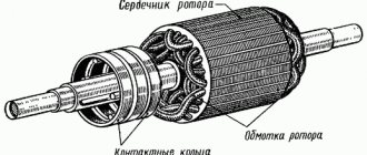
Brief theoretical information. Three-phase asynchronous motor
Three-phase asynchronous motor
The purpose of the work
is to study the operation of an asynchronous motor with a squirrel-cage rotor and measure its mechanical and operating characteristics.
Brief theoretical information
Simplicity of design, operational reliability, efficiency and low cost are the main reasons for the widespread use of asynchronous motors in industry.
Stator magnetic field rotation frequency n
1 is determined by the formula
n
1 = , rpm (1)
where f
1 — network frequency, Hz;
R
— number of pairs of poles.
Difference in rotor speed n
2 and stator fields
n
1 are expressed by slip
s
= (2)
Slip increases with increasing load on the motor shaft. In modern engines, depending on the series and purpose, slip at rated load is 2...8%. At idle, the slip is only 0.1...0.3%.
If we consider slip at rated load s
n equal to 5%, then we can indicate the rotor speed of asynchronous motors when powered from a network with
f
= 50 Hz.
Table 1.
| Rotation speed at s n = 5% | Number of pole pairs on the stator |
| Stator fields n 1, rpm | |
| Rotor n 2, rpm |
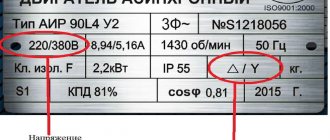
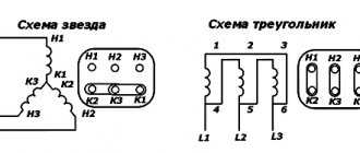
Asynchronous motors of low and medium power, thanks to the possibility of connecting the stator windings according to the Y/Δ or Δ/Y scheme, can operate when powered by two corresponding voltages 380/220 V.
On the engine nameplate this is indicated as
Y/Δ, 380/220 V.
The simplest way to start a motor with a squirrel-cage rotor and a rated power of up to 100 kW is to directly connect the stator winding to a three-phase circuit.
The engine rotor speed can be expressed by the formula
n
1 = (1–
s
1), rpm. (3)
Electric power P
1, consumed by an asynchronous motor from the network, is spent on useful power
P
2 on the shaft and power losses for heating the stator and rotor windings Δ
Р
e1 and Δ
Р
e2, losses in the stator magnetic circuit and in the rotor steel from eddy currents and on hysteresis Δ
Р
st and friction losses in bearings Δ
Р
tr.
Thus, the power balance in the engine will be expressed as follows:
R
1 =
Р
2 + Δ
Р
tr + Δ
Р
e + Δ
Р
st, W. (4)
The active power of the motor consumed from the network is calculated by the formula
R
1 = 3
R
1ph, W, (5)
where P
1ph =
U
1ph ∙
I
1 – power of one phase, measured with a wattmeter, W.
Mechanical power developed on the motor shaft, P
the fur consists of the useful power on the shaft
P
2 and friction losses
P
tr
R
fur =
P
2 +
P
tr, W. (6)
Mechanical power can be determined by the formula
R
fur = 0.105
M
∙
n
2, W, (7)
where M
– torque, Nm;
n
2 – rotor rotation speed, rpm.
Magnetic losses in the stator magnetic circuit, i.e. losses in steel Δ Р
st, practically do not change with increasing load on the
P
2 shaft and are called constant.
On the other hand, heating losses of the stator and rotor windings, i.e. copper losses Δ P
e depend on the load and are called variables.
Efficiency of an asynchronous motor η
is defined as the ratio of useful power on the shaft
P
2 to that consumed from the network
P
1
η
= = (8)
Net engine power on shaft P
2 can be determined by the formula
R
2 =
M
∙ ω =
M
∙ , W (9)
or P
2 = 0.105
M
∙
n
2, W. (10)
Then
η
= = = , (11)
where U
1f, V;
I
1f, A;
Cos
φph – voltage, current and power factor of the motor phase.
R
1 – consumed active power of the engine.
Power factor Cos
φф depends on the load on the motor shaft and is determined by the ratio of the active power to the total power of the motor stator phase
Cos
φф = = (12)
In laboratory work, the power factor Cos
φ is measured directly by a phase meter, and can also be calculated from the readings of a wattmeter, voltmeter and ammeter included in the motor phase (Fig. 1).
The main characteristic of an asynchronous motor, called mechanical, is the dependence n
2 =
f
(
M
), i.e. dependence of the engine rotor speed on torque (Fig. 1).
Fig.1. Mechanical characteristics of an asynchronous motor.
The torque of an asynchronous motor is determined by the formula
M
= , Nm (13)
where U
1ph – phase voltage of the stator winding, V;
n
1 – synchronous rotation frequency of the stator magnetic field, rpm;
s
– sliding;
R
– number of pole pairs;
R
1,
R
2',
Х
к – parameters of the equivalent circuit of an asynchronous motor, Ohm (Fig. 2).
Fig.2. Replacement diagram of an asynchronous motor.
The torque of an asynchronous motor in laboratory work is measured on the scale of an electromagnetic brake connected to the motor shaft, in g∙cm (1 Nm = 9800 g∙cm).
The torque of an asynchronous motor depends on the magnitude of the squared voltage supplied to the stator phase, slip s
, frequency of current in the stator
f
1 and design parameters of the motor (number of pole pairs, active resistance of motor windings, etc.).
By changing the slip value s
with the remaining constants in the torque formula, you can obtain different values of the moments
M
n,
M
cr,
M
p shown in the natural mechanical characteristic (Fig. 1).
Rated torque M
n can be determined by the formulas
M
n = 9.55, Nm (14)
or
M
n = 9.55, Nm (15)
The catalog for asynchronous motors contains passport data: P
2n,
U
1n,
s
n,
n
2n,
M
n,
M
cr/
M
n,
Cos
φn and the method of connecting the stator windings.
The properties of an asynchronous motor are most fully and clearly revealed using performance characteristics.
The performance characteristics include the dependence of the rotor speed n
2, torque
M
, slip
s
stator phase current
I
1ph, power factor
Cos
φ and efficiency.
engine from the useful power on the P
2 shaft at
U
1 =
Const
and
f
1 =
Const
.
When P
2, the slip value
s
increases, because as the load on the shaft increases, the rotor speed decreases (Fig. 3).
Fig.3. Dependence of the slip value on the useful power on the shaft.
At idle, when P
2 = 0, the rotor rotation speed
n
2 can be taken equal to the rotation frequency of the stator magnetic field
n
1 and
s
= 0.
Since P
2 ≈
Р
fur, and
Р
fur = 0.105
M
∙
n
2, then the operating characteristic
n
2 =
f
(
P
2) is similar to the mechanical characteristic (Fig. 4).
Fig.4. Mechanical characteristics of an asynchronous motor.
Torque M
on the rotor shaft can be considered to consist of a useful torque, spent on performing useful work, and an idle torque
M
0, spent on overcoming friction.
This proportion of torque is practically independent of the load on the P
2 shaft.
Thus, we can assume that M
≈ .
If the rotor speed were constant, then the performance characteristic would be linearly increasing. In reality, the rotor speed n
2 decreases with increasing
P
2, and therefore the characteristic
M
=
f
(
P
2) is nonlinear and the torque
M
quickly increases with increasing
P
2 (Fig. 5).
Fig.5. Dependency M
=
f
(
P
2)
Curve I
1f =
f
(
P
2) is similar to the operating characteristic
M
=
f
(
P
2) (Fig. 6).
Fig.5. Dependency I
1f =
f
(
P
2)
If you do not take into account the no-load current of the motor, which is 7...8% of I
1ph, then the current in the stator phase is proportional to the useful power
P
2 and increases as it increases.
At idle, P
2 = 0 and
I
1ph =
I
10 (Fig. 5).
When the engine is idling, the power factor Cos
φ of the motor is small and usually does not exceed 0.2, but then with increasing load on the
P
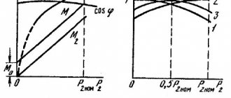
2 shaft it quickly grows and reaches a maximum at power close to the rated one (Fig. 6).
This happens because as the load increases, the active power P
1 consumed from the network increases, and the reactive power
Q
1 remains almost unchanged.
As a result, the main magnetic flux remains practically constant. At loads greater than rated, Cos
φ decreases due to a significant increase in reactive powers associated with the influence of leakage fluxes.
Fig.6. Dependency Cos
φ =
f
(
Р
2)
Analyzing the dependence η
=
f
(
P
2), it can be seen that when the load on the shaft
P
2 changes, the constant losses Δ
P
tr and Δ
P
st practically do not change, and the initial increase in losses in the active resistance of the windings Δ
P
e is significantly less than the increase in useful power on the shaft .
At P
2 =
P
2n, the constant losses Δ
P
tr and Δ
P
st become equal to the variable Δ
P
e, and the share of losses in the energy balance already becomes commensurate with
P
2. As a result, the efficiency begins to decrease somewhat (Fig. 7).
Fig.7. Dependence η
=
f
(
P
2)
Work plan.
1. Familiarize yourself with the design of an asynchronous motor, types of measuring instruments, and the design of an electromagnetic brake. In the form provided in the laboratory work report, write down the technical data of the instruments and electrical equipment used.
2. Assemble the electrical circuit (Fig. and present it to the teacher or laboratory assistant for checking.
3. After checking the circuit, set the autotransformer (AT) regulator to position “0” and turn on the rectifier.
4. Turn on the phototachometer and press the “Start” button on the electrical stand.
5. Using an autotransformer (AT), change the resistance moment of the electromagnetic brake within 0...0.01 Nm (0,100,200,300,400,500,600,700,800,900,1000 g∙cm).
6. Measure the following quantities using instruments: voltage on the motor phase U
1ph according to the voltmeter V, current in phase
I
1ph according to the ammeter A1, active power consumed by the motor phase
P
1ph according to the wattmeter W, rotor speed
n
according to the phototachometer.
Make measurements for 11 different moments of resistance on the motor shaft.
Enter the experimental data into Table 2.
table 2
| No. | Measured values | Calculated values | |||||||||
| M Nm | U 1ph V | I 1ph A | P 1ph W | n 2 rpm | Cosφ _ | M Nm | P 2 W | P 1 W | S 1 VA | Cosφ _ | s |
| … |
7. At the end of the measurements, press the “Stop” button, turn off the power to the circuit and show the results to the teacher.
8. After receiving permission from the teacher, disassemble the diagram.
9. Using the measured data, calculate the torque on the motor shaft M
, Nm;
useful shaft power P
2, W;
active power consumed by the motor P
1, W;
total power consumed by the engine S
1;
slip s
;
power factor Cos
φ and efficiency
η
.
10. Based on the measured and calculated data, plot the engine characteristics on graph paper:
a) mechanical characteristic n
2 =
f
(
M
);
b) performance characteristics s
=
f
(
P
2);
n
2 =
f
(
P
2);
M
=
f
(
P
2);
I
1ph =
f
(
P
2).
c) operating characteristic Cos
φ =
f
(
P
2), measured and calculated.
11. Materials of measurements and calculations, obtained characteristics should be presented in the form of a laboratory report.
Rice. 8. Electrical circuit for studying a three-phase asynchronous motor with a squirrel-cage rotor:
A1 – 1 A AC ammeter; A2 – DC ammeter 1 A; W – 150 W wattmeter; F – phase meter for 127 V 5 A in the “receiver” position; V – 150 V AC voltmeter; AT – autotransformer; ET – electromagnetic brake.
Control questions
1. Design and principle of operation of an asynchronous motor.
2. What is slip ( s
xx,
s
start)?
3. Why is the motor called asynchronous?
4. Condition for the occurrence of a rotating magnetic field.
5. Standard values of n
1 (magnetic rotation speed
fields).
6. Idling mode of an asynchronous motor.
7. Why I
xx of the asynchronous motor is greater than
I
0 of the transformer.
8. Equivalent circuit of an asynchronous motor in idle mode.
9. Simplified equivalent circuit.
10.Why I
starting an asynchronous motor is 6...8 times more than
I
n?
11. Mechanical characteristics of an asynchronous motor n
=
f
(
M
);
n
=
f
(
s
) (natural and rheostat).
12. Kloss formula.
13.Regulating the speed of an asynchronous motor.
14.Advantages and disadvantages of each method.
15.Types of rotors (short-circuit and phase).
16. Purpose of a wound rotor.
17. Limitation method I
start-up of an asynchronous motor with a squirrel-cage rotor.
18. Limitation method I
starting of an asynchronous motor with a wound rotor.
19.Energy diagram. Power losses in an asynchronous motor.
20.Efficiency of an asynchronous motor.
21.Advantages and disadvantages of an asynchronous motor.
Three-phase asynchronous motor
The purpose of the work
is to study the operation of an asynchronous motor with a squirrel-cage rotor and measure its mechanical and operating characteristics.
Brief theoretical information
Simplicity of design, operational reliability, efficiency and low cost are the main reasons for the widespread use of asynchronous motors in industry.
Stator magnetic field rotation frequency n
1 is determined by the formula
n
1 = , rpm (1)
where f
1 — network frequency, Hz;
R
— number of pairs of poles.
Difference in rotor speed n
2 and stator fields
n
1 are expressed by slip
s
= (2)
Slip increases with increasing load on the motor shaft. In modern engines, depending on the series and purpose, slip at rated load is 2...8%. At idle, the slip is only 0.1...0.3%.
If we consider slip at rated load s
n equal to 5%, then we can indicate the rotor speed of asynchronous motors when powered from a network with
f
= 50 Hz.
Table 1.
| Rotation speed at s n = 5% | Number of pole pairs on the stator |
| Stator fields n 1, rpm | |
| Rotor n 2, rpm |
Asynchronous motors of low and medium power, thanks to the possibility of connecting the stator windings according to the Y/Δ or Δ/Y scheme, can operate when powered by two corresponding voltages 380/220 V.
On the engine nameplate this is indicated as
Y/Δ, 380/220 V.
The simplest way to start a motor with a squirrel-cage rotor and a rated power of up to 100 kW is to directly connect the stator winding to a three-phase circuit.
The engine rotor speed can be expressed by the formula
n
1 = (1–
s
1), rpm. (3)
Electric power P
1, consumed by an asynchronous motor from the network, is spent on useful power
P
2 on the shaft and power losses for heating the stator and rotor windings Δ
Р
e1 and Δ
Р
e2, losses in the stator magnetic circuit and in the rotor steel from eddy currents and on hysteresis Δ
Р
st and friction losses in bearings Δ
Р
tr.
Thus, the power balance in the engine will be expressed as follows:
R
1 =
Р
2 + Δ
Р
tr + Δ
Р
e + Δ
Р
st, W. (4)
The active power of the motor consumed from the network is calculated by the formula
R
1 = 3
R
1ph, W, (5)
where P
1ph =
U
1ph ∙
I
1 – power of one phase, measured with a wattmeter, W.
Mechanical power developed on the motor shaft, P
the fur consists of the useful power on the shaft
P
2 and friction losses
P
tr
R
fur =
P
2 +
P
tr, W. (6)
Mechanical power can be determined by the formula
R
fur = 0.105
M
∙
n
2, W, (7)
where M
– torque, Nm;
n
2 – rotor rotation speed, rpm.
Magnetic losses in the stator magnetic circuit, i.e. losses in steel Δ Р
st, practically do not change with increasing load on the
P
2 shaft and are called constant.
On the other hand, heating losses of the stator and rotor windings, i.e. copper losses Δ P
e depend on the load and are called variables.
Efficiency of an asynchronous motor η
is defined as the ratio of useful power on the shaft
P
2 to that consumed from the network
P
1
η
= = (8)
Net engine power on shaft P
2 can be determined by the formula
R
2 =
M
∙ ω =
M
∙ , W (9)
or P
2 = 0.105
M
∙
n
2, W. (10)
Then
η
= = = , (11)
where U
1f, V;
I
1f, A;
Cos
φph – voltage, current and power factor of the motor phase.
R
1 – consumed active power of the engine.
Power factor Cos
φф depends on the load on the motor shaft and is determined by the ratio of the active power to the total power of the motor stator phase
Cos
φф = = (12)
In laboratory work, the power factor Cos
φ is measured directly by a phase meter, and can also be calculated from the readings of a wattmeter, voltmeter and ammeter included in the motor phase (Fig. 1).
The main characteristic of an asynchronous motor, called mechanical, is the dependence n
2 =
f
(
M
), i.e. dependence of the engine rotor speed on torque (Fig. 1).
Fig.1. Mechanical characteristics of an asynchronous motor.
The torque of an asynchronous motor is determined by the formula
M
= , Nm (13)
where U
1ph – phase voltage of the stator winding, V;
n
1 – synchronous rotation frequency of the stator magnetic field, rpm;
s
– sliding;
R
– number of pole pairs;
R
1,
R
2',
Х
к – parameters of the equivalent circuit of an asynchronous motor, Ohm (Fig. 2).
Fig.2. Replacement diagram of an asynchronous motor.
The torque of an asynchronous motor in laboratory work is measured on the scale of an electromagnetic brake connected to the motor shaft, in g∙cm (1 Nm = 9800 g∙cm).
The torque of an asynchronous motor depends on the magnitude of the squared voltage supplied to the stator phase, slip s
, frequency of current in the stator
f
1 and design parameters of the motor (number of pole pairs, active resistance of motor windings, etc.).
By changing the slip value s
with the remaining constants in the torque formula, you can obtain different values of the moments
M
n,
M
cr,
M
p shown in the natural mechanical characteristic (Fig. 1).
Rated torque M
n can be determined by the formulas
M
n = 9.55, Nm (14)
or
M
n = 9.55, Nm (15)
The catalog for asynchronous motors contains passport data: P
2n,
U
1n,
s
n,
n
2n,
M
n,
M
cr/
M
n,
Cos
φn and the method of connecting the stator windings.
The properties of an asynchronous motor are most fully and clearly revealed using performance characteristics.
The performance characteristics include the dependence of the rotor speed n
2, torque
M
, slip
s
stator phase current
I
1ph, power factor
Cos
φ and efficiency.
engine from the useful power on the P
2 shaft at
U
1 =
Const
and
f
1 =
Const
.
When P
2, the slip value
s
increases, because as the load on the shaft increases, the rotor speed decreases (Fig. 3).
Fig.3. Dependence of the slip value on the useful power on the shaft.
At idle, when P
2 = 0, the rotor rotation speed
n
2 can be taken equal to the rotation frequency of the stator magnetic field
n
1 and
s
= 0.
Since P
2 ≈
Р
fur, and
Р
fur = 0.105
M
∙
n
2, then the operating characteristic
n
2 =
f
(
P
2) is similar to the mechanical characteristic (Fig. 4).
Fig.4. Mechanical characteristics of an asynchronous motor.
Torque M
on the rotor shaft can be considered to consist of a useful torque, spent on performing useful work, and an idle torque
M
0, spent on overcoming friction.
This proportion of torque is practically independent of the load on the P
2 shaft.
Thus, we can assume that M
≈ .
If the rotor speed were constant, then the performance characteristic would be linearly increasing. In reality, the rotor speed n
2 decreases with increasing
P
2, and therefore the characteristic
M
=
f
(
P
2) is nonlinear and the torque
M
quickly increases with increasing
P
2 (Fig. 5).
Fig.5. Dependency M
=
f
(
P
2)
Curve I
1f =
f
(
P
2) is similar to the operating characteristic
M
=
f
(
P
2) (Fig. 6).
Fig.5. Dependency I
1f =
f
(
P
2)
If you do not take into account the no-load current of the motor, which is 7...8% of I
1ph, then the current in the stator phase is proportional to the useful power
P
2 and increases as it increases.
At idle, P
2 = 0 and
I
1ph =
I
10 (Fig. 5).
When the engine is idling, the power factor Cos
φ of the motor is small and usually does not exceed 0.2, but then with increasing load on the
P
2 shaft it quickly grows and reaches a maximum at power close to the rated one (Fig. 6).
This happens because as the load increases, the active power P
1 consumed from the network increases, and the reactive power
Q
1 remains almost unchanged.
As a result, the main magnetic flux remains practically constant. At loads greater than rated, Cos
φ decreases due to a significant increase in reactive powers associated with the influence of leakage fluxes.
Fig.6. Dependency Cos
φ =
f
(
Р
2)
Analyzing the dependence η
=
f
(
P
2), it can be seen that when the load on the shaft
P
2 changes, the constant losses Δ
P
tr and Δ
P
st practically do not change, and the initial increase in losses in the active resistance of the windings Δ
P
e is significantly less than the increase in useful power on the shaft .
At P
2 =
P
2n, the constant losses Δ
P
tr and Δ
P
st become equal to the variable Δ
P
e, and the share of losses in the energy balance already becomes commensurate with
P
2. As a result, the efficiency begins to decrease somewhat (Fig. 7).
Fig.7. Dependence η
=
f
(
P
2)
Work plan.
1. Familiarize yourself with the design of an asynchronous motor, types of measuring instruments, and the design of an electromagnetic brake. In the form provided in the laboratory work report, write down the technical data of the instruments and electrical equipment used.
2. Assemble the electrical circuit (Fig. and present it to the teacher or laboratory assistant for checking.
3. After checking the circuit, set the autotransformer (AT) regulator to position “0” and turn on the rectifier.
4. Turn on the phototachometer and press the “Start” button on the electrical stand.
5. Using an autotransformer (AT), change the resistance moment of the electromagnetic brake within 0...0.01 Nm (0,100,200,300,400,500,600,700,800,900,1000 g∙cm).
6. Measure the following quantities using instruments: voltage on the motor phase U
1ph according to the voltmeter V, current in phase
I
1ph according to the ammeter A1, active power consumed by the motor phase
P
1ph according to the wattmeter W, rotor speed
n
according to the phototachometer.
Make measurements for 11 different moments of resistance on the motor shaft.
Enter the experimental data into Table 2.
table 2
| No. | Measured values | Calculated values | |||||||||
| M Nm | U 1ph V | I 1ph A | P 1ph W | n 2 rpm | Cosφ _ | M Nm | P 2 W | P 1 W | S 1 VA | Cosφ _ | s |
| … |
7. At the end of the measurements, press the “Stop” button, turn off the power to the circuit and show the results to the teacher.
8. After receiving permission from the teacher, disassemble the diagram.
9. Using the measured data, calculate the torque on the motor shaft M
, Nm;
useful shaft power P
2, W;
active power consumed by the motor P
1, W;
total power consumed by the engine S
1;
slip s
;
power factor Cos
φ and efficiency
η
.
10. Based on the measured and calculated data, plot the engine characteristics on graph paper:
a) mechanical characteristic n
2 =
f
(
M
);
b) performance characteristics s
=
f
(
P
2);
n
2 =
f
(
P
2);
M
=
f
(
P
2);
I
1ph =
f
(
P
2).
c) operating characteristic Cos
φ =
f
(
P
2), measured and calculated.
11. Materials of measurements and calculations, obtained characteristics should be presented in the form of a laboratory report.
Rice. 8. Electrical circuit for studying a three-phase asynchronous motor with a squirrel-cage rotor:
A1 – 1 A AC ammeter; A2 – DC ammeter 1 A; W – 150 W wattmeter; F – phase meter for 127 V 5 A in the “receiver” position; V – 150 V AC voltmeter; AT – autotransformer; ET – electromagnetic brake.
Control questions
1. Design and principle of operation of an asynchronous motor.
2. What is slip ( s
xx,
s
start)?
3. Why is the motor called asynchronous?
4. Condition for the occurrence of a rotating magnetic field.
5. Standard values of n
1 (magnetic rotation speed
fields).
6. Idling mode of an asynchronous motor.
7. Why I
xx of the asynchronous motor is greater than
I
0 of the transformer.
8. Equivalent circuit of an asynchronous motor in idle mode.
9. Simplified equivalent circuit.
10.Why I
starting an asynchronous motor is 6...8 times more than
I
n?
11. Mechanical characteristics of an asynchronous motor n
=
f
(
M
);
n
=
f
(
s
) (natural and rheostat).
12. Kloss formula.
13.Regulating the speed of an asynchronous motor.
14.Advantages and disadvantages of each method.
15.Types of rotors (short-circuit and phase).
16. Purpose of a wound rotor.
17. Limitation method I
start-up of an asynchronous motor with a squirrel-cage rotor.
18. Limitation method I
starting of an asynchronous motor with a wound rotor.
19.Energy diagram. Power losses in an asynchronous motor.
20.Efficiency of an asynchronous motor.
21.Advantages and disadvantages of an asynchronous motor.
Calculation of internal combustion engine power based on injector performance
An equally effective indicator of the power of a car engine is the performance of the injectors. Previously, we looked at its calculation and relationship, therefore, it will not be difficult to calculate the amount of horsepower using the formula. The estimated power is calculated according to the following scheme:
Where, the load factor is no more than 75-80% (0.75...0.8), the mixture composition at maximum performance is somewhere around 12.5 (rich), and the BSFC coefficient will depend on what kind of engine you have, naturally aspirated or turbocharged (atmo - 0.4-0.52, for turbo - 0.6-0.75).
Having found out all the necessary data, enter the indicators into the appropriate cells of the calculator and by clicking the “Calculate” button you will immediately receive a result that will show the real engine power of your car with a slight error. Please note that you do not necessarily need to know all the parameters presented; you can clear the power of the internal combustion engine using a separate method.
The value of the functionality of this calculator lies not in calculating the power of a stock car, but if your car has been tuned and its weight and power have undergone some changes.
Active reactive and apparent power
Content:
- Active, reactive and apparent power formulas
- How to find active, reactive and apparent power
- Video
In electrical engineering, among the many definitions, concepts such as active, reactive and apparent power are often used. These parameters are directly related to the current and voltage in a closed electrical circuit when any consumers are turned on. To carry out calculations, various formulas are used, among which the main one is the product of voltage and current. First of all, this concerns constant voltage. However, in AC circuits, power is divided into several components noted above. The calculation of each of them is also carried out using formulas, thanks to which you can obtain accurate results.
Active, reactive and apparent power formulas
The main component is considered to be active power. It is a quantity characterizing the process of converting electrical energy into other types of energy. That is, in another way, it is the speed at which electricity is consumed. It is this value that is displayed on the electricity meter and paid by consumers. Active power is calculated using the formula: P = U x I x cosph.
Unlike active energy, which refers to the energy that is directly consumed by electrical appliances and converted into other types of energy - thermal, light, mechanical, etc., reactive power is a kind of invisible assistant. With its participation, electromagnetic fields are created that are consumed by electric motors. First of all, it determines the nature of the load, and can not only be generated, but also consumed. Reactive power calculations are made using the formula: Q = U x I x sinф.
Total power is a quantity consisting of active and reactive components. It provides consumers with the necessary amount of electricity and keeps them in working condition. For its calculations, the formula is used: S = .
How to find active, reactive and apparent power
Active power refers to the energy that is irreversibly consumed by a source per unit of time for the consumer to perform some useful work. In the process of consumption, as already noted, it is converted into other types of energy.
In an alternating current circuit, the value of active power is defined as the average instantaneous power over a specified period of time. Consequently, the average value over this period will depend on the phase angle between current and voltage and will not be equal to zero, provided that active resistance is present in this section of the circuit. The last factor determines the name of active power. It is through active resistance that electricity is irreversibly converted into other types of energy.
When performing calculations of electrical circuits, the concept of reactive power is widely used. With its participation, processes such as the exchange of energy between sources and reactive elements of the circuit occur. This parameter will be numerically equal to the amplitude possessed by the variable component of the instantaneous power of the circuit.
There is a certain dependence of reactive power on the sign of the angle φ shown in the figure. In this regard, it will have a positive or negative meaning. Unlike active power, which is measured in watts, reactive power is measured in var - reactive volt-amperes. The final value of reactive power in branched electrical circuits is the algebraic sum of the same powers for each element of the circuit, taking into account their individual characteristics.
The main component of total power is the maximum possible active power at a previously known current and voltage. In this case, cosф is equal to 1 when there is no phase shift between current and voltage. The total power also includes a reactive component, which is clearly seen from the formula presented above. The unit of measurement for this parameter is volt-ampere (VA).
electric-220.ru
FAQ
How to calculate the power of an internal combustion engine?
Engine power in kW can be calculated from engine size and crankshaft speed. The formula for calculating engine power is: Ne = Vh * Pe * n / 120 (kW), where: Vh - engine volume, cm³ n - number of crankshaft revolutions per minute Pe - average effective pressure, MPa
What coefficient should be taken into account when calculating engine power?
The power factor (cosϕ) for calculating the power of an electric motor is taken equal to 0.8 for low-power motors (less than 5.5 kW) or 0.9 for motors with a power of over 15 kW.
How to calculate engine power from torque?
To determine the engine power in kilowatts, when the torque is known, you can use the following formula: P = Mcr * n/9549, where: Mcr – torque (Nm), n – crankshaft speed (rpm), 9549 – coefficient for converting revolutions to rpm.
What is an electric motor?
An electric motor is a device that converts electrical energy into mechanical energy. The operation of most units depends on the interaction of the magnetic field with the rotor winding, which is expressed in its rotation. They operate from DC or AC power sources. The power supply can be a battery, an inverter or a power outlet. In some cases, the engine works in reverse, that is, it converts mechanical energy into electrical energy. Such installations are widely used in power plants powered by air or water flow.
Electric motors are classified by type of power source, internal design, application and power. Also, AC drives may have special brushes. They operate on single-phase, two-phase or three-phase voltage and are air or liquid cooled. AC motor power formula
P = U x I,
where P is power, U is voltage, I is current.
General purpose drives with their own sizes and characteristics are used in industry. The largest engines with a power of more than 100 Megawatts are used in the power plants of ships, compressor and pumping stations. Smaller sizes are used in household appliances, such as a vacuum cleaner or fan.
see also
Asynchronous motor for everyday use- Asynchronous motor with built-in encoder
- Laying the stator winding of an asynchronous motor
- Asynchronous motor air 80v2 u3
- How to increase the power of an asynchronous motor
- Shaded pole asynchronous motor
- Asynchronous motor ave 072 4у4
- How to increase the speed of an asynchronous motor
Asynchronous motors with combined windings- Comparison of asynchronous and synchronous motors
- Circuit diagram of an asynchronous motor with back-braking
What is apparent, active and reactive power?
WHAT IS TOTAL, ACTIVE AND REACTIVE POWER? FROM COMPLEX TO SIMPLE.
In everyday life, almost everyone comes across the concept of “electrical power”, “power consumption” or “how much electricity does this thing consume”. In this collection, we will explain the concept of electrical power of alternating current for technically savvy specialists and show in the picture the electrical power in the form of “how much electricity does this thing consume” for people with a humanitarian mindset :-). We reveal the most practical and applicable concept of electrical power and deliberately avoid describing differential expressions of electrical power.
WHAT IS AC POWER?
In AC circuits, the formula for DC power can only be used to calculate instantaneous power, which varies greatly over time and is useless for practical calculations. Direct calculation of average power requires integration over time. To calculate power in circuits where voltage and current vary periodically, average power can be calculated by integrating the instantaneous power over the period. In practice, the greatest importance is the calculation of power in circuits of alternating sinusoidal voltage and current.
In order to connect the concepts of total, active, reactive power and power factor, it is convenient to turn to the theory of complex numbers. We can assume that the power in an alternating current circuit is expressed by a complex number such that the active power is its real part, the reactive power is the imaginary part, the apparent power is the module, and the angle φ (phase shift) is the argument. For such a model, all the relations written below turn out to be valid.
Active power (Real Power)
The unit of measurement is watt (Russian designation: W, kilowatt - kW; international: watt -W, kilowatt - kW).
The average value of instantaneous power over a period T is called active power, and
expressed by the formula:
In single-phase sinusoidal current circuits, where υ and Ι are the rms values of voltage and current, and φ is the phase shift angle between them. For non-sinusoidal current circuits, the electric power is equal to the sum of the corresponding average powers of the individual harmonics. Active power characterizes the rate of irreversible conversion of electrical energy into other types of energy (thermal and electromagnetic). Active power can also be expressed in terms of current, voltage and the active component of the circuit resistance r or its conductivity g according to the formula. In any electrical circuit of both sinusoidal and non-sinusoidal current, the active power of the entire circuit is equal to the sum of the active powers of the individual parts of the circuit; for three-phase circuits, the electrical power is defined as the sum of the powers of the individual phases. With the total power S, the active one is related by the relation.
In the theory of long lines (analysis of electromagnetic processes in a transmission line, the length of which is comparable to the length of the electromagnetic wave), a complete analogue of active power is transmitted power, which is defined as the difference between the incident power and the reflected power.
Reactive Power
The unit of measurement is reactive volt-ampere (Russian designation: var, kVAR; international: var).
Reactive power is a quantity characterizing the loads created in electrical devices by fluctuations in the energy of the electromagnetic field in a sinusoidal alternating current circuit, equal to the product of the rms values of voltage U and current I, multiplied by the sine of the phase angle φ between them:
(if the current lags behind the voltage, the phase shift is considered positive, if it leads, it is considered negative). Reactive power is related to total power S and active power P by the ratio: .
The physical meaning of reactive power is energy pumped from the source to the reactive elements of the receiver (inductors, capacitors, motor windings), and then returned by these elements back to the source during one oscillation period, referred to this period.
It should be noted that the value of sin φ for values of φ from 0 to plus 90° is a positive value. The value of sin φ for values of φ from 0 to minus 90° is a negative value. According to the formula
reactive power can be either a positive value (if the load is active-inductive in nature) or negative (if the load is active-capacitive in nature). This circumstance emphasizes the fact that reactive power does not participate in the operation of electric current. When a device has positive reactive power, it is customary to say that it consumes it, and when it produces negative power, it produces it, but this is purely a convention due to the fact that most power-consuming devices (for example, asynchronous motors), as well as purely active loads, are connected through a transformer, are active-inductive.
Synchronous generators installed in power plants can both produce and consume reactive power depending on the magnitude of the excitation current flowing in the generator rotor winding. Due to this feature of synchronous electrical machines, the specified network voltage level is regulated. To eliminate overloads and increase the power factor of electrical installations, reactive power compensation is carried out.
The use of modern electrical measuring transducers on microprocessor technology allows for a more accurate assessment of the amount of energy returned from an inductive and capacitive load to an alternating voltage source.
Power can be either a positive value (if the load is active-inductive in nature) or negative (if the load is active-capacitive in nature). This circumstance emphasizes the fact that reactive power does not participate in the operation of electric current. When a device has positive reactive power, it is customary to say that it consumes it, and when it produces negative power, it produces it, but this is purely a convention due to the fact that most power-consuming devices (for example, asynchronous motors), as well as purely active loads, are connected through a transformer, are active-inductive.
Synchronous generators installed in power plants can both produce and consume reactive power depending on the magnitude of the excitation current flowing in the generator rotor winding. Due to this feature of synchronous electrical machines, the specified network voltage level is regulated. To eliminate overloads and increase the power factor of electrical installations, reactive power compensation is carried out.
The use of modern electrical measuring transducers on microprocessor technology allows for a more accurate assessment of the amount of energy returned from inductive and capacitive loads to an alternating voltage source
Apparent Power
The unit of total electrical power is volt-ampere (Russian designation: VA, VA, kVA-kilo-volt-ampere; international: V A, kVA).
Total power is a value equal to the product of the effective values of the periodic electric current I in the circuit and the voltage U at its terminals: ; the ratio of total power with active and reactive power is expressed in the following form: where P is active power, Q is reactive power (with an inductive load Q›0, and with a capacitive load Q‹0). The vector relationship between total, active and reactive power is expressed by the formula:
Total power has practical significance as a value that describes the loads actually imposed by the consumer on the elements of the supply network (wires, cables, distribution boards, transformers, power lines), since these loads depend on the current consumed, and not on the energy actually used by the consumer. This is why the total power of transformers and distribution boards is measured in volt-amperes rather than watts.
All of the above formulaic and textual descriptions of total, reactive and active powers are visually and intuitively clear in the following figure
Specialists of the NTS-group company (TM Elektrokaprizam-NET) have extensive experience in selecting specialized equipment for building systems for providing vital facilities with uninterrupted power supply. We are able to take into account as efficiently as possible many electrical and operational parameters, which allow us to choose an economically feasible option for building an uninterruptible power supply system.
© The material was prepared by specialists of the NTS-group company (TM Elektrokaprizam-NET) using information from open sources, incl. from the free encyclopedia Wikipedia https://ru.wikipedia.org
electrokaprizam.net