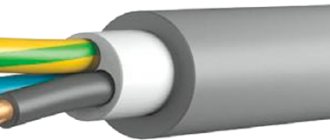
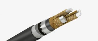
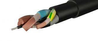
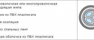
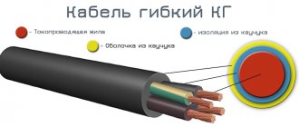
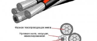
ASBL cable design
Structurally, it is the following system.
- The wire is based on an aluminum core, which serves to transmit current. It is sectoral in shape, consisting of one or more wires.
- For phase and belt insulation of cores, layers of impregnated paper are used. Between them there are bundles twisted from paper - filling the space between the conductors, they eliminate the risk of short circuiting and fire of the system.
- The cushion, which softens and strengthens the structure of the cable, consists of layers of crepe paper, bitumen, and PET tape.
- The entire structure is tightly wrapped in a sheath of lead.
- As protection, a cushion made of flexible durable materials is used, which contains bitumen, glass yarn and steel armored tapes.
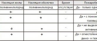
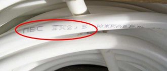
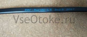
Decoding of ASBL markings
As with any other type of cable and wire product, you can get the first information about the product by studying its labeling. For this brand, the name includes an alphanumeric designation.
Look at the letter part, the ASBL cable marking is deciphered as follows:
- A - means that the current-carrying conductors are made of aluminum;
- C - indicates that this brand is equipped with a lead sheath;
- B - indicates the presence of an armored braid, which is made of steel tapes.
- l - means that an additional tape made of bitumen, polymer, lavsan is laid under the armor; depending on the manufacturer, its composition may differ. There are also ASB2l brands that have a double layer of additional tape under the armor.
Let's consider an example of cable marking ASBL 4×70; here the abbreviation indicates that the cable has aluminum conductors, a lead sheath, armor and bitumen tapes. The number 4 indicates the number of cores, and 70 indicates the cross-section of each of them, in this case 70 mm2 each. To better understand the features of the ASBL cable device, consider its design.
Technical characteristics of the ASBL cable
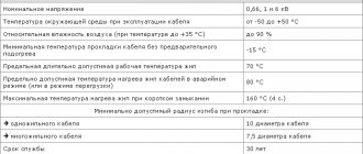
Uwork - 1 kV, 6 kV, 10 kV. Uconstant — 2.5 kV, 15 kV, 25 kV. Rated frequency - 50 Hz.
Operating mode, t - from -50 °C to +50 °C. Relative air humidity (at t0 +35 °C) – up to 98%; Service life: 30 years. Warranty: 4.5 years (from the date of start of operation). Carrying out installation work without preheating at temperatures from -15 °C;
Tmax permissible core heating: - for 1 kV devices: +80 °C; — for 6 kV devices: +60 — +80 °С; — for 10 kV devices: +60 — +70 °С. — in emergency condition: +90 °C. — with a short circuit: +200°С.
Rmin of bending during installation: - for single-core cables - 25 external ?; - for multi-core cables - 15 external ones;
Construction length: - with a cross-section from 70 mm2 - 300-450 m. - with a cross-section from 90 mm2 to 120 mm2 - 250-400 m. - with a cross-section from 150 mm2 and above - 200-350 m.
Areas of use
| Recommended area of application | In the absence of tensile forces (when laid in the ground and water), in the absence of danger of mechanical damage (when laid in air) |
| In soil with moderate corrosive activity | Yes |
| In highly corrosive soil | Yes |
Cables with a viscous impregnating composition without the use of locking couplings do not allow installation on routes with a level difference between the highest and lowest points of the cable location of more than 15-25 meters, while larger values apply to low-voltage cables with an aluminum sheath and armored ones. Cables with non-draining impregnating composition allow installation without limiting the difference in levels.
Estimated weight for ASB cable
| Number of cores, cross-section, mm2 | Mass 1 km. cable, kg. | ||
| 1 kV | 6 kV | 10 kV | |
| 3x35 3x50 3x70 3x95 3x120 3x150 3x185 3x240 3x35 + 1x16 3x50 + 1x25 3x70 + 1x50 3x95 + 1x70 3x120 + 1x70 3x150 + 1x70 3x185 +1x95 4x35 4x50 4x70 4x95 4x120 4x150 4x185 4x240 | 1770 2038 2460 3022 3556 4033 4687 5574 2023 2382 2835 3516 4148 4675 5469 2127 2462 2935 3649 4301 4897 5725 6840 | 2575 5946 3430 3976 4491 5014 5695 — — — — — — — — — — — — — — — — | 3170 3574 4069 4631 5181 5750 6454 — — — — — — — — — — — — — — — — |
Number and cross-section of cores in cables
| Number of cores | Nominal conductor cross-section, mm2 Nominal cable voltage, kV | ||
| 1 | 6 | 10 | |
| 1 | 10-800 | ||
| 3 | 6-240 | 10-240 | 16-240 |
| 4 | 16-185 | ||
The paper insulation of cables must be impregnated with a viscous or non-drip insulating impregnation compound. In impregnated paper insulation, the tapes should not have folds or tears.
The insulating impregnating non-drip composition should not leak out at the long-term permissible heating temperature of the cable cores.
In paper insulated cables for voltages of 6 kV and more, the coincidence of more than three tapes located one above the other and two tapes directly adjacent to the core or screen superimposed on the core is not allowed.
The coincidence of longitudinal folds or cuts over a length of more than 50 mm in two tapes located one above the other is considered one coincidence.
The insulated cores of multi-core cables must be twisted, filling the spaces between the cores with paper bundles.
Insulated sector cores of multi-core cables for a voltage of 1 kV can be twisted without filling.
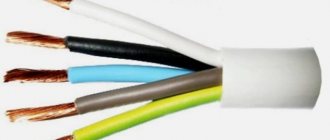
The insulated cores of multi-core cables must have a distinctive color or number designation.
The color marking must be durable, not erasable and distinguishable. Marking should be done using colored tapes on the cores or natural colored tapes with stripes that differ from each other in color.
Marking with numbers is done by printing or embossing and must be legible. The color of the numbers when printed must differ from the color of the core insulation. The numbers must have the same color.
With a digital designation, the first core should have the number 1 on the insulation surface or the top strip, the second core should have the number 2, the third core should have 3, and the fourth core should have 4. In this case, number 1 corresponds to white or yellow, number 2 to blue or green, number 3 to red or crimson, number 4 - brown or black.
The insulation of a conductor of a smaller cross-section (zero) can be of any color and may not have a digital designation.
When designating insulated cores with numbers, the distance between them should not be more than 35 mm.
Belt insulation with a nominal thickness in accordance with the table must be applied over the twisted insulated cores of multi-core cables
Under the cable sheath on the surface of the insulation or under the belt insulation on a special tape, no more than every 300 mm, the identification number of the manufacturer and the year of manufacture of the cable must be clearly marked.
In cables with a diameter under the sheath of less than 20 mm, the use of a colored distinctive thread is allowed.
The tape should be made of natural-colored paper. The absence of tape along a cable length of more than 1 m is not allowed. The width of the tape is at least 10 mm. The height of the cipher is at least 6 mm.
Where is this cable used?
The laying of an armored conductor can take place in closed buildings and structures, along the walls and facades of buildings. Installation and use are permissible both underground and in the ground. The design of the cable guarantees safety; it certainly does not become distorted or stretched. The design of the cable creates all conditions for ensuring safety, since there is no risk of deformation and cannot be stretched. The cable material resists all temperature changes well. Thanks to this, it can be laid in almost any climatic conditions from moderate to cold.
ASBL , among other things, can be used in transport electrical networks if the conductor does not stretch. When laying takes place on highways and transport lines, the level of stray currents is not standardized in any way. Can be laid in closed areas, in tunnels and along walls. Thanks to reliable armor, excellent resistance to any physical impacts is achieved.
Cable operating conditions
NYM cable
Such wires can be laid either by laying them on a horizontal surface or by giving them an inclined position. It is possible to place cables indoors or along its facade. As for laying wires in trenches, it can be done in places where conditions do not predispose the products to stretching, and there is no increased corrosion activity. It is permissible to lay them in cold climates, since the cable components are quite resistant to temperature fluctuations. An important condition is that the ambient temperature does not fall below -50 degrees Celsius. Indicators for stray currents during underground installation are not regulated.
Important! Installation of power conductors in transport networks with electrification is allowed only if conditions are provided that protect the product from stretching.
Weights of single-core cables with aluminum conductors for voltage 1 kV, kg/km
| Nominal cross-section of cores, mm2 | ASBL |
| 10 | 740 |
| 16 | 820 |
| 25 | 930 |
| 35 | 1050 |
| 50 | 1150 |
| 70ozh | 1450 |
| 70 | 1600 |
| 95ozh | 1700 |
| 95 | 1800 |
| 120ozh | 1900 |
| 120 | 2100 |
| 150ozh | 2100 |
| 150 | 2400 |
| 185ozh | 2700 |
| 185 | 2800 |
| 240ozh | 2900 |
| 240 | 3300 |
| 300 | 3800 |
| 400 | 4400 |
| 500 | 5300 |
| 625 | 6100 |
| 800 | 7300 |
Weights of three-core cables with aluminum conductors for voltage 1 kV, kg/km
| Nominal cross-section of cores, mm2 | ASBL |
| 6 | 1100 |
| 10 | 1500 |
| 16 | 1700 |
| 25 | 1750 |
| 35 | 2050 |
| 50 | 2400 |
| 70ozh | 2800 |
| 70 | 3000 |
| 95ozh | 3450 |
| 95 | 3700 |
| 120ozh | 4000 |
| 120 | 4300 |
| 150ozh | 4550 |
| 150 | 4900 |
| 185ozh | 5300 |
| 185 | 5700 |
| 240ozh | 6300 |
| 240 | 6700 |
Fire safety ASBL
Thanks to the durable sheath and the presence of cushion filling, the conductors are resistant to fire and have a high degree of fire safety. This makes it possible to use these products in various environmental conditions, but installing them in warehouses and mines is impractical.
The flexibility of the product allows it to be stored in skeins
The electrical product ASBL has a wide range of applications due to its flexibility, strength and resistance to environmental influences. When choosing, you need to pay attention to the number of cores, their diameter and what installations the sample is designed to work with.
Laying cables along a metal fence
According to the Electrical Installation Rules, there are no restrictions, with the exception of general safety requirements (see above). The most important thing is to ensure the electrical safety of people. If the shell is damaged for any reason, the entire surface of the fence will become a source of electrical hazard. Therefore, a metal fence with electrical wiring must be grounded.
Steel support pillars concreted to any depth on which the fence is attached are not grounding. It is necessary to organize a protective circuit and connect it to the plane of the fence.
Moreover, all shields must be connected to each other by reliable conductors.
The cable is installed using standard fasteners, just like on a regular wall.
If the fence consists of a strong frame welded from profile pipes, the optimal installation route is the upper horizontal guide. Of course, subject to the height rules: if the distance to the ground is less than 2.75 m, the cable must be in a sleeve or box.
A separate topic is fences made of mesh or lattice. The easiest way is a support cable. Suspension points are located on support posts. But such fences rarely exceed a height of 2.5 meters, so you will still have to lay the cable in a sleeve or box. The second option is preferable from an aesthetic point of view.
At the same time, the box or corrugation can be attached either to poles or directly to the mesh. The same goes for installing junction boxes.