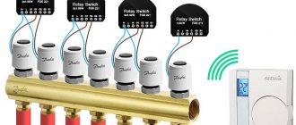
Grounding is one of the main factors providing protection against electric shock. In accordance with Chapter 1.7 of the PUE, all grounding systems for electrical installations can be divided into two groups: - systems with a solidly grounded neutral, these include the TN grounding system (NC, TN-CS, TN-S) and the TT grounding system; — systems with an isolated neutral, these include the IT grounding system;
The first letter of the abbreviation indicates the nature of the grounding of the power source, and the second - the nature of the grounding of the open conductive parts of the power receiver:
- T (from the French terre - earth) - grounded;
- N (from the French neutre - neutral) - connection to the neutral of the power source (grounding);
- I (from the French isolé - isolated) - isolated from grounding.
The article also contains the following abbreviations:
- N - functional (working) zero - neutral conductor used to connect an electrical receiver.
- PE - protective zero - a protective conductor designed for grounding electrical equipment housings.
- PEN is a conductor that combines the functions of zero protective and zero working conductors.
Now we will analyze in detail the listed types of grounding systems.
TN-C grounding system
The TN-C system is a TN system in which the neutral protective and neutral working conductors are combined in one conductor along its entire length. That is, with this system, a common PEN conductor is used, which is used both to connect electrical receivers and to ground their open conductive parts (cases).
TN-C grounding system diagram:
As can be seen in the diagram, with this system, the current-carrying housings of electrical equipment are grounded, this is necessary so that when a phase wire is shorted to the housing of the electrical receiver, due to its breakage or damage to the insulation, a short circuit occurs, which, in turn, would lead to the activation of protective equipment (circuit breaker) and power outage.
The main disadvantage of the TN-C system is the loss of its protective functions in the event of a burnout (break) of the PEN conductor, while a life-threatening electrical potential may arise on the grounded electrical equipment housing.
Due to the insufficient degree of protection, this system is not currently used, but it is still found in older buildings. When reconstructing old buildings, the TN-C grounding system is replaced with a TN-CS or TN-S system.
Advantages and disadvantages
There is only one advantage to such a system: such a system is quite easy to install and does not require large financial investments. It makes sense to pay more attention to the disadvantages of this scheme. If there is grounding according to this scheme, there is a risk of receiving an electric shock, which can sometimes lead to bad consequences. So, if the electrician you hired advises you to carry out the installation according to this scheme, you should think about refusing his services and look for another one. Those protective switching devices that are installed with such a scheme can only provide protection against short circuit currents! Such a scheme cannot protect people from electric shock.
What to do if it becomes known that this system is installed? If it becomes known about the presence of this scheme, then it must be remembered that, during any reconstruction, such a system must be replaced with a safer one (the installation of this system is prohibited these days).
All organizations providing energy supply, whose balance sheet includes residential buildings equipped with a similar scheme, have recommendations for converting them to TN-CS systems, or to TN-S when upgrading electrical supply systems. An example of this is the installation of an EPS (potential equalization system). In addition, if a grounding system made according to this scheme is used, then the PEN wire, under no circumstances, can be used as a grounding conductor for devices. Otherwise, in the event of an emergency, there is a fairly high possibility of getting an electric shock, since the device body will be energized.
When I took an electrical safety exam (at work), I was asked what the difference was between a four-wire line and a five-wire line. To this I replied that in a four-wire line there are three phases and zero, and in a five-wire line there are three phases, zero and ground. This was enough for the examiner and we moved on to the next question. But, after all, I wanted to talk about this more, discuss all sides of both line options. Perhaps the examiner would tell me about something I don’t know or don’t know well. Well, okay, what happened, happened and it’s not for me to judge. The main thing is that the answer to the question was counted as correct and I, as a result, passed the exam.
I would like to hope that my article helped to understand the topic presented and, after reading it, no questions regarding this power supply system will arise. If so, then I didn’t work in vain,
Grounding system TN-CS
The TN-CS system is a TN system in which the functions of the neutral protective and neutral working conductors are combined in one conductor in some part of it, starting from the power source. In other words, with this system there is a PEN conductor which, in a certain part of this system, is divided into a zero working (N-conductor) and a zero protective (PE-conductor).
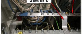
According to clause 1.7.135 of the PUE, at the point where the PEN conductor is divided into the neutral protective (PE) and neutral working (N) conductors, it is necessary to provide separate clamps or busbars for the conductors, connected to each other. The PEN conductor of the supply line must be connected to the terminal or bus of the neutral protective PE conductor.
Thus, the TN-CS grounding system diagram will look like this:
Note: the jumper between the buses must have a cross-section no less than the cross-section of the PEN conductor.
This system is more reliable and provides a higher level of electrical safety than the TN-C system; in addition, the TN-CS system provides protection against zero loss, and its installation is slightly more expensive than the TN-C system.
However, this system also has a significant drawback - if the PEN conductor is damaged in the network section between the power source and the building, a life-threatening electrical potential will appear on all electrical equipment housings connected to the PE conductor.
To prevent such a development of events with the TN-CS system, the PEN conductor is re-grounded, as shown in the diagram.
Due to the low cost of the TN-CS system and its good protective characteristics, this system is currently widely used.
Typical mistakes and tips for the home handyman
The good intention of the owners of apartments equipped with electrical wiring operating according to the TN-C scheme to follow the recommendations on grounding electrical appliances is quite often accompanied by serious violations of the rules that can cause great harm to people around them. Let's look at typical mistakes when connecting devices yourself.
Connecting electrical appliance housings to zero
This method is called zeroing. It was widely used as a protective technique when performing short-term work on old power tools equipped with a metal casing with poor insulation. Modern industry does not produce such devices.
Operating principle: in the event of an insulation failure and a phase potential appears on the housing, a short circuit current occurs, which is quickly switched off by protective circuit breakers.
Dangers of zeroing:
- The absence of precisely adjusted protective devices in the event of damage to the device does not exclude the emergence of dangerous potential for a person in contact with the housing
- Sometimes “electricians” make mistakes by confusing phase with zero. In this case, the phase will be deliberately supplied to the housing
- in cases of zero damage, the circuit does not work
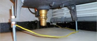
Connecting electrical appliance housings to metal building structures
Water supply networks, water heating lines, elevator shaft housings and some other elements are permanently located in the ground. Folk craftsmen use them for grounding.
Risks of the method:
- electrical contact with ground is not monitored
- in case of pipeline repairs, the chain is broken
- plastic pipes installed in sections act as insulators
- when potential appears on the device body, a random person in any apartment may suffer if he touches the heating radiator, water tap and finds himself in the path of current flow
Unauthorized splitting of the PEN conductor on the floor panel
At first glance, this method seems to be the most optimal solution. The electrical wiring of the apartment is redone according to a three-wire circuit to connect the neutral and PE conductor in strict accordance with the rules. All that remains is to connect to the grounding loop and the “home electrician” independently makes the splitting on the floor distribution panel.
This is dangerous because:
- the approved and completed electrical wiring design for the entire building is grossly violated
- preconditions for electrical injuries and threats of equipment damage are created
- if any malfunctions occur in the electrical wiring of the building, representatives of utility services can “appoint” the owner of the apartment as the culprit, which will lead to scandals, fines, inspections by various commissions and other troubles
- Housing and communal services electricians involved in building maintenance will not take into account the specifics of the modifications carried out during their work. This may cause accidents
Grounding system TN-S
The TN-S system is a TN system in which the neutral protective and neutral working conductors are separated throughout its entire length.
Grounding system TN-S diagram:
This system provides a high level of security, because it eliminates the possibility of dangerous electrical potential arising on electrical equipment housings if the supply line is damaged.
However, the TN-S system has not become widespread due to its main drawback - high cost, which is due to the need to connect consumer electrical installations to the power source with five wires for a three-phase connection or three wires for a single-phase connection, while the domestic energy industry is focused on four-wire three-phase power supply circuits, this means that if you decide to connect via the TN-S system, connection to existing power supply networks will be impossible; for such a connection it will be necessary to conduct a separate five-wire line from the power source (transformer substation).
Execution examples
Rice. 2. TN-S single-phase two-wire system with separated grounded linear conductor and protective conductor throughout the system
Rice. 3. TN-S three-phase three-wire system with separated grounded linear conductor and protective conductor throughout the system
Fig 4. TN-S three-phase four-wire system
TT grounding system
A CT system is a system in which the neutral of the power source is solidly grounded, and the exposed conductive parts of the electrical installation are grounded using a grounding device that is electrically independent of the solidly grounded neutral of the source.
TT grounding system diagram:
In accordance with clause 1.7.59. PUE power supply of electrical installations via the TT system is allowed only in cases where electrical safety conditions in the TN system cannot be ensured . In addition, in such electrical installations there must be an automatic power shutdown with the mandatory use of an RCD. In this case, the following condition must be met:
Ra Ia ≤ 50 V
where Ia is the tripping current of the protective device; Ra is the total resistance of the grounding conductor and the grounding conductor, when using an RCD to protect several electrical receivers - the grounding conductor of the most distant electrical receiver.
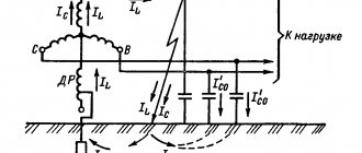
Peculiarities
With the TN-C system grounding type (see Figure 1), one of the live parts of the power source is grounded, usually the neutral of the transformer. All exposed conductive parts of Class I electrical equipment installed in a building's electrical installation have an electrical connection to the grounded neutral point of the transformer. To provide this connection, PEN conductors are typically used in both the low-voltage electrical distribution network and the building electrical installation. If the electrical distribution network includes an overhead power line (OHL), then its PEN conductor is usually grounded at several points, performing the so-called re-grounding of the PEN conductor.
The PEN conductor of the electrical distribution network “originates” from the corresponding protective grounding and neutral bus (PEN bus) of the low-voltage switchgear of the transformer substation and “ends” at the input terminal of the ASU of the electrical installation of the building. The PEN conductors of the building's electrical installation begin from this terminal, to which, as a rule, all exposed conductive parts of class I electrical equipment are connected. That is, the PEN conductor, performing the functions of a protective conductor, permeates the entire electrical distribution system from the power source to the exposed conductive parts of the building's electrical installation .
However, in some cases, exposed conductive parts of Class I electrical equipment may be connected not only to PEN conductors, but also to the protective PE conductors of the building's electrical installation. For example, when three-phase Class I electrical equipment is used in a building's electrical installation, which does not have a neutral and does not require neutral conductors for its normal operation (see Figure 2), protective conductors are connected to their exposed conductive parts.
If the electrical installation of the building connecting to the overhead line and the branch from the overhead line to the input is made with bare wires, then the PEN conductor of the electrical distribution network “ends” at the terminal connecting it with the PEN conductor of the input cable to the electrical installation of the building.
IT grounding system
IT system - a system in which the neutral of the power supply is isolated from earth or grounded through devices or devices having high resistance, and the exposed conductive parts of the electrical installation are grounded.
IT grounding system diagram:
The IT system is used, as a rule, in special-purpose electrical installations that are subject to increased safety requirements, for example laboratories, coal mines, and can also be used in hospitals for emergency power supply and lighting, etc.