What does the system include?
The system is sold as a set, but if necessary, its components can be purchased separately.
Included in the package:
- Vertical metal one and a half meter threaded rods, processed with copper.
Pin 58-11″UNC
|
- Brass threaded couplings that serve as connecting elements between pins.
Connecting coupling MS-58-11
|
- Brass clamps connect a metal pin to a metal strip.
| Universal brass clamps MS-58-11 |
- Tips placed on a rod inserted vertically into the ground. There are several types of tips designed for ordinary and very hard soil, which greatly facilitate immersion due to the sharp lower end.
Tip 58-11″UNC
|
- A landing pad with an impact screw used to transmit force from a vibrating hammer.
| The landing pad serves to transfer forces from the jackhammer to the rod. Landing pad 5/8”-11 UNC
|
Impact nozzle NU
|
- To protect against corrosion, all threaded connecting elements are coated with the included anti-corrosion graphite paste. It does not spread even with strong heating and serves to maintain electrical resistance.
- Plastic, moisture-resistant, resistant to aggressive solutions, anti-corrosion tape serves to protect all metal grounding elements from destruction.
To service the system, an inspection hatch is required.
| 1. Landing pad with impact propeller. 2. Installation coupling. 3. A clamp that holds the rod in a vertical position. 4. Coupling coupling. 5. Ground rod. 5. Metal tip. |
Modular-pin grounding design
Types of ground loops
To instantly drain the electric current into the ground, the subsystem distributes it into several electrodes, which are located at a distance from each other. This allows you to increase the dispersion area. There are 2 options for making grounding.
Linear
In this case, 2-3 electrodes are placed in a semicircle or in a line. Such a contour is used if the area of the land plot does not allow for a closed structure.
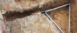
Triangle
In this case, use 3 pins and connect them together with metal strips. The finished product is in the shape of a triangle with equal sides.
DIY system installation
Installation can be done with the help of specialists or on your own. To complete the work you will need:
- a jackhammer or hammer drill, which greatly simplifies the installation of the device;
- resistance meter.
System installation steps:
- We calculate the required burial depth, determine the required number of rods and the amount of their immersion into the ground.
- Having retreated 1.5 m from the wall of the building, we dig a hole 20 cm wide, long and deep, retreating one and a half meters from the wall.
- We install a resistance meter near the installation site, drive measuring electrodes into the ground at a distance of 10 and 25 meters from it, and connect the device.
Tip #1. If it is not possible to measure the resistance after installing each pin, you can deepen the system to a lower level from 15 to 30 meters, and call laboratory representatives who will make all the necessary measurements and draw up documentation.
Layout of electrodes for a modular-bayonet system
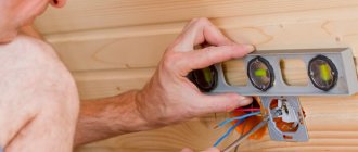
- We prepare the device. We treat the threads on both sides with graphite paste (or a similar composition). We put the tip on the thread, and install the coupling on the other end. We screw on the landing impact nozzle, which will be in contact with the vibrating hammer. A special clamp will hold the rod in a vertical position.
- We insert the prepared rod into the hole with the tip down. Using a jackhammer, drive the rod into the ground, leaving 20 cm above the surface for joining with the second rod. Remove the landing impact nozzle.
- We measure the resistance by connecting the meter to the rod.
- We treat the coupling with conductive anti-corrosion paste and screw the next rod into it, and again the coupling treated with the paste onto it. We install the nozzle and hammer it into the ground according to the same pattern using a hammer. We measure resistance. We increase the rod again, repeating this action until the resistance reaches 4 ohms.
- We drive the last pin to such a depth that the coupling can be unscrewed from it, and leave about 10 cm above the ground.
Ready-made modular-pin grounding
- Next, we connect the vertical grounding conductor to the horizontal grounding conductor. The clamp consists of three plates and has four bolted fastenings. It has connectors for a grounding rod, cable and steel strip. We screw the clamp onto the outer end of the pin - with the side intended for the rod. We screw a cable or metal strip onto the other side of the clamp, placing a plate between them that protects the elements in contact with each other from corrosion. We treat all bolted connections with plastic, moisture-resistant tape.
- We install the inspection hatch.
Tip #2. Instead of a ready-made inspection hatch, which is quite large in size, you can use a sewer coupling. A plywood plug with a hole for the rod is attached to the bottom of the coupling.
If the soil allows, the pins can be deepened up to 40 meters. If it is impossible to immerse the rods in the ground to the required depth, conventional grounding conductors should be installed. Their number will depend on the soil resistance.
Using the modular system, you can perform various types of grounding: single point, focal, comb, multipoint. The installation method is selected depending on the type of soil and area of the site for installation.
Grounding of ventilation air ducts: PUE
- All metal components that are not live during operation of the main equipment must be grounded.
- It is allowed to connect air ducts of decentralized ventilation systems to the busbars of electrical panels that supply fans or air conditioners.
- The presence of visible jumpers created using a copper conductor on any flange connections or other methods of fixing devices is mandatory. The requirements also apply to cases where insulating rubber gaskets are missing. Tackling of small steel staples by other welding is permitted.
According to some electricians, due to the connection of devices to each other, grounding through the fan housing is allowed. But other electricians say otherwise. According to their assurances, the presence of protective grounding in air ducts is mandatory only for certain areas. Namely those that are located directly near people. While other areas do not need to be grounded.
However, for your maximum safety, we recommend that you arrange protection in accordance with current regulations.
← Previous article Next article →
Soil resistance indicators
The magnitude of the soil resistance shows how well the current will flow in it. The value of this indicator largely depends on the composition of the soil, the fraction and density of particles adjacent to each other.
Soil resistance table
| Soil type | Resistance, Ohm/m |
| Permanently frozen ground | 500-50000 |
| Dry sand | 400-4000 |
| Wet sand | 10-400 |
| Loam | 10-150 |
| Clay | 20-60 |
No. 2. Basic elements of a boiler room in a private house
It’s good if the house is small, and the problems of heating and hot water supply can be solved with one small double-circuit gas boiler. But in most cases this will not be enough - you will need a whole set of equipment, which may consist of a set of the following elements:
- The boiler is the heart of the entire boiler room. It will be responsible for heating water for the heating system. Heat can be produced by burning different types of fuel: liquid, gaseous or solid. A special case is electric boilers. In some cases, two boilers are installed at once to provide a private home with complete energy independence;
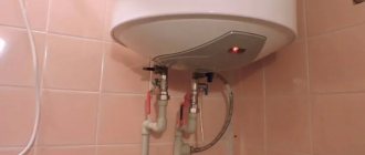
- boiler. If a single-circuit boiler is used, then a boiler will have to be used to heat water for the hot water supply system;
- expansion tank. Water from the heating system will flow into this container if the pressure in it increases. Thus, pipes and radiators are protected from breakthrough;
- heat accumulator. It is not always installed, despite the fact that it is a very useful element. This container accumulates superheated coolant, “excess heat,” which is then supplied to the heating system. This significantly saves resources and increases safety. The presence of this element is especially important for solid fuel boilers and in the presence of two boilers of different types;
- distribution manifold. Necessary for proper distribution of coolant throughout the system, regulates temperature;
- circulation pump. Necessary only in systems where the coolant circulates forcibly;
- chimney. Necessary for removing combustion products outside the house. A chimney is not needed only for an electric boiler;
- safety and control group - a set of devices that monitor the temperature and pressure in the boiler and system. This may also include sensors that monitor the air condition in the boiler room;
- automation receives commands from the user regarding the required temperature, collects security group data and allows you to correctly adjust the main parameters of the system;
- shut-off valves are necessary to control the flow of coolant;
- pipes through which water from the boiler goes to the radiators;
- a filter is necessary to purify water before it enters the boiler and boiler. If the water in the region is saturated with salts and contains mechanical impurities, then you cannot do without a filter - otherwise the equipment may soon fail.
It is not necessary to use all of these elements; their selection depends on many factors. First of all, this is the size of the house and the type of fuel.
Devices requiring grounding
Some electrical appliances require additional grounding beyond the grounded outlet. Without a quality grounding device, the operation of the following devices could potentially be dangerous
- Microwave. A terminal for connecting to ground is installed on the rear wall. But the instructions for it indicate only the general phrase “grounding required” and nothing else is specified. Without a connection to grounding, a microwave oven can create a background hazardous to human health.
- Washing machine. Often, touching it causes a slight tingling and tingling sensation - an electric current is passed. To avoid this and completely protect yourself, you need to ground the washing machine.
- Electric oven.
- If you connect the computer case to ground, the Internet speed will increase several times, and the system will not freeze.
1.2. Requirements for a protective grounding system
1.2.1. In underground mine workings, a common grounding network must be installed, to which all objects to be grounded must be connected.
The resistance of the grounding device used for electrical installations of various voltages must meet the requirements for grounding electrical installations that require the lowest resistance of the grounding device.
1.2.2. For intrinsically safe telephone communication equipment and its cable couplings, in a network section with cables without armor, local grounding is allowed without connection to the general grounding network. The resistance of this independent grounding must be taken such that the product of the active resistance of the grounding and the fault current flowing in it does not exceed the permissible value of the safe touch voltage.
1.2.3. The main grounding circuit and grounding loop must be made of bare steel conductor with a cross-section of at least 100 mm2. Conductors must be placed so as to prevent mechanical damage or corrosion (especially at their connection points) and so that they can be monitored.
1.2.4. The main grounding circuit must have at least two main artificial grounding conductors located in different places.
1.2.5. When calculating, the grounding resistance should be taken such that the touch voltage on electrical installation housings during a ground fault does not exceed the permissible value according to GOST 12.1.038, but not more than 2 Ohms.
Comparison of modular and conventional grounding
A comparison of conventional grounding and a modular system shows many obvious advantages of modular pin grounding.
| Conventional grounding | Modular pin grounding |
| Welding required | Welding work is not performed |
| A labor-intensive and lengthy process that requires large volumes of excavation work | Even one person without experience can handle the installation |
| A truck is required for transportation | The entire system can be carried by one person |
| Material cutting required | Installation occurs using couplings and bolted connections, no cutting required |
| Significant area required | Required installation area - 1 sq. m |
Purpose of calculating protective grounding
The grounding device installed on the consumer side is designed to protect not only personnel servicing electrical installations, but also ordinary users.
Important! Dangerous potential can reach metal parts of equipment while working with it completely accidentally (due to damage to wire insulation, for example).
A complete grounding calculation guarantees the formation of reliable contact of the protective device with the ground, leading to the spreading of current and a reduction in the level of dangerous voltage.
Thus, the purpose of calculating grounding devices is to create conditions that eliminate the risk of damage to living organisms by high potential by reducing it at the point of closure. In the absence of a well-designed and functional grounding conductor, any touch to the frame of damaged equipment is tantamount to direct contact with the phase conductor.
Galvanized ground rods
One of the production methods is also cold galvanic galvanizing in a container with an electrolyte. The process is slightly slower than copper plating, since zinc has slightly worse adhesive properties than copper.
Hot-dip galvanized grounding rods are obtained by immersion in a bath of liquid zinc for a certain time and subsequent cooling. Depending on the technological parameters of the process (t of the zinc melt, time spent in the solution, cooling method, pin steel grade, etc.), it is possible to obtain different thicknesses of the zinc layer on the surface of the electrode.
How to make a triangle ground?
- Advantage of triangular contour shape
- Installation steps
Advantage of triangular contour shape
What advantage does a triangle have over a striped outline? It lies in the fact that such a structure occupies a smaller area, and therefore there will be significantly less excavation work. And it is much easier to connect the pins in a hole than in a narrow and long trench. However, the most important advantage of triangular grounding is the reliable functioning of the protection, because if the metal jumper between the electrodes is damaged, the grounding device will still work (on the other side).
The height of each grounding electrode has certain standards and is 2 - 3 meters. The shape of the arrangement of electrodes in the ground is an isosceles triangle, the distance between which must be at least 1.2 m. In order to obtain a good contact connection, a metal plate is used, which is applied by welding. To connect the ground from the circuit to the house, it is recommended to use a busbar made of the same metal or a steel wire of a suitable cross-section. The dimensions of the corner must be at least 50x50 mm.
You can make a triangle grounding using the following step-by-step instructions:
At the selected location we mark the places where vertical electrodes will be buried. Then you need to dig a trench up to one meter deep. The depth should be below freezing of the ground. The lines of the structure must form a triangle, the length of the side of which is indicated in the calculations. Then you need to dig a trench from the structure to the power panel. The corner of the circuit to which the shield will be connected is selected as the closest one. This is done to save materials.
Next, you need to drive the electrodes into the ground, leaving 20 cm above the ground.
Using a steel strip it is necessary to create a closed system. It is welded to the electrodes and forms a triangle.
A strip is laid from the nearest point to the power panel and displayed on the wall.
Weld a bolt to the strip connected to the cabinet, with its thread facing outward. This means that the head of the bolt will be welded. To connect the grounding to the panel in the house, it is important to drill a hole in the wall in advance for the grounding cable. Using a nut, the grounding cable is attached to the bolt. After this, it is necessary to treat the welds and joints with special anti-corrosion substances and sealant.
The instructions in pictures are as follows:
The final stage of installing a ground electrode yourself will be checking the grounding resistance. To do this, you need to have a special electrical device called an ohmmeter. But since such a device is not cheap, it is better to invite a specialist from the energy management. The specialist needs to take measurements and enter data into the grounding circuit passport.
It is important to check in dry weather, since atmospheric moisture can cause measurement errors. The loop resistance standard should not exceed 4 Ohms for a 220 Volt network
If the resistance exceeds this indicator, then the grounding needs to be modified. To do this, you need to add another grounding conductor or make a diamond-shaped structure.
If the parameters meet all standards and requirements and the low resistance of the circuit is confirmed, then the trench can be buried. This is done with homogeneous soil, without crushed stone and debris. The grounding should be connected to the panel not in parallel, but separately for each technical unit.
There is another way to check resistance without calling a specialist. To do this, it is enough to have a lamp with a power of at least 100 W. The light source is connected to the system with one contact, and to the phase with the second. If the triangle is installed correctly, the light will glow brightly. If it shines dimly, it means the contacts between the ground electrodes are weak and the joints will need to be redone. If the light does not come on at all, then the triangle is not installed correctly. In this case, you should check the diagram itself and see where the error was made.
The video below clearly shows how to assemble a triangular-shaped ground loop:
That's all I wanted to tell you about how to make triangle grounding with your own hands. We hope the provided diagrams, photos and installation instructions were useful to you!
Resistance of vertical ground electrode
There is a calculation formula that allows you to calculate the resistance of both a single grounding rod and any vertical grounding structure.
The formula contains a resistance equivalent, which is used only if the installation site has a multi-layer primer (2 or more different layers). We will not give its calculation here, but will limit ourselves to presenting a table for different types of soils, from which the value P , simply assuming the presence of a single layer.
The climatic seasonality coefficient Km is presented in the following table.
Designs of pin grounding conductors
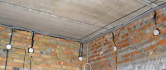
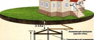
Pin grounding conductors are installed at a distance of 1 meter from the foundation of the house. The general design principle of pin grounding conductors is as follows:
General design of a pin ground electrode
Metal corners or pipes are driven into the ground. They are called electrodes. The electrodes are driven three meters into the ground and connected to each other with a metal corner. The connection is made by welding. The distance between the electrodes must be at least 1.2 meters. This entire structure is a pin grounding conductor. The grounding conductors are connected to the main grounding bus (GZB) of the house using copper wire PV3 (PV three). The connection of the wire with the grounding conductor and the main switch is bolted using copper cable lugs.
Note: PV3 wire is a single-core wire with copper stranded core and PVC insulation. Operating voltage up to 470 volts at alternating voltage and 1000 volts at constant voltage. The wire is resistant to mechanical bending, shock and linear stretching.
Various designs of pin ground electrode
Triangle. This is a pin grounding design in which electrodes are driven into the ground at the corners of a triangle with sides of 1.3 meters. The distance from the foundation to the nearest vertex of the grounding triangle is 1 meter.
"Crow's Foot". This is a pin grounding design in which electrodes are driven into the ground along the corner of the house. The distance between the electrodes is 3 meters. The distance from the angle electrode to the foundation is 1 meter. The number of crow's foot grounding conductors must correspond to the number of lightning rods installed for the house.
Row grounding. This pin grounding design provides for the arrangement of pin-electrodes in a row every 1.2-1.3 meters.
I repeat, all the corners (pins, electrodes) are driven into the ground to a depth of 3 meters, connected to each other with 40x40x4 mm corners or a 40x4 mm metal strip. Connection using a fold. The pin grounding switch itself is connected to the main grounding bus (GSB) of the house, installed in the water distribution device (WDU) or next to it, with a PV 3 wire. The connection is made using cable lugs.
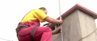
How to properly drive an electrode into the ground?
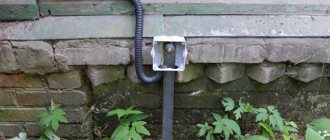
Pipe stands
To install an entry device in a commercial building or country house, you must use a pipe stand.
Its main task is to fix the power wire that leads to the shield, as well as install the shield itself. According to the requirements of the PUE rules, the pipe stand requires mandatory grounding.
Not far from the shield, you need to drill a hole through which it is important to place a grounding bolt. Both the pipe stand itself and the shield require high-quality grounding. A metal corner one and a half meters long should be driven in not far from the rack. Next comes the connection of the pipe stand, shield and corner.
The zero bus is also protected. The neutral wire marked SIP4, which comes from the support, must be connected to it. To perform the operation, you need to use the yellow-green wire marked PV-3, on which the tips are installed. At this point, the grounding of the metal pipe stand can be considered complete.
Copper-plated ground rods
They are widely used as a replacement for copper ones due to the high cost of the latter. The mention of copper in the name makes them popular with buyers, although in itself it does not differ much in terms of characteristics from galvanized analogues and is inferior to stainless steel ones. In the meantime, you need to be careful not to buy a low-quality fake.
ATTENTION! Among copper-plated grounding conductors, low-quality products (usually Chinese handicraft production) are often found. The main material is made of cheap steel, the quality and thickness of the copper galvano coating leaves much to be desired. Often copper is applied by conventional knurling, which is unacceptable. Such a product placed in the ground will not withstand the stated service life and mechanical requirements for the design.
In industrial production, steel is copper plated by galvanic method in an electrochemical Cu solution under automatic control.
Grounding the gas pipeline rules - Iskra Gas
In the process of laying pipelines for any purpose, it is necessary to take care of the safety of their operation. It is important to prevent the negative impact of a strong electrical discharge on both the pipeline itself and the substances transported through it. Especially for this it is important to install grounding.
Explosive areas
In some cases, explosive workshops operate on the territory of manufacturing enterprises.
Here it is important to efficiently remove static electricity that occurs during the friction of a liquid-like substance against the internal walls of the pipes.
In such situations, it is necessary to reduce the potential removal. A good measure is to install an intermediate grounding of the pipeline and use cable conductors with a non-metallic sheath. These, for example, include the AASHV brand.
Effect of insulation
The insulation resistivity indicator can significantly influence the characteristic features of the pipeline.
According to studies, the level of resistance in the grounding of a pipeline using bitumen insulation can greatly depend on the potential difference between the soil and the pipeline itself.
If the difference varies within a few hundred volts, glow discharge may occur at defective locations, which in turn reduces the ground resistance.
If the potential difference is one kilovolt or more, an arc discharge appears between the soil and the pipeline. It, accordingly, greatly reduces the resistance of the installed grounding. Portable grounding can also be used, in which the clamp is the main part.
Preparation for repair
In preparation for repair work, it is necessary to free the pipeline from the transferred substance, and then purge it with special technical nitrogen. It is worth making sure there is grounding.
If the design does not provide for the installation of a temperature condenser, flushing with water steam is strictly prohibited. This will lead to an increase in internal pressure, which leads to rupture of the structure.
Thus, the heating system will fail.