Among the various possibilities for making your home safe, grounding in a private home occupies a special place: the electrical network diagram of any modern home will not be approved if it does not provide for a connection to a grounding loop.
Grounding diagram for a private house Source tirez.ru
There are several options and schemes for grounding a private house, plus clear requirements of the PUE (electrical installation rules) - all this must be known and understood in order for the electricity in the house to be safe.
Why do you need grounding in a private house: principle of operation
Grounding in a private home is considered an important part of the power supply system. It is installed for the following purposes:
- Protection of home inhabitants from electric shock (when touching a device with damaged electrical wiring insulation);
- Correct operation of modern electrical devices;
- Safe operation of gas equipment;
- Effective operation of lightning protection.
The principle of operation of the system is based on the elementary laws of physics, which say that electric current always moves in the direction of least resistance.
If the insulation of the device is damaged, the current flows out (short circuit) to the housing. This situation is fraught with malfunctions and breakdowns, not to mention the danger for a person to receive a sensitive discharge by accidentally touching the surface with his hand.
Video description
A succinct and clear grounding diagram for a private house, why it is needed and what it should be like, is shown in the following video:
If there is grounding, the current is distributed taking into account the resistance value of the body and the grounding loop of the house (in inverse proportion).
Carefully designed protective grounding creates an electrical circuit with a resistance significantly lower than that of the human body. The current passing through a person will not have a dangerous effect, and the main charge will go into the ground.
The passage of electric current through the human body in a system without grounding and with grounding Source plotnikov-pub.ru
The main element of grounding a private house is the grounding loop - the PUE defines it as metal conductors and grounding electrodes (rods or pipes) buried in the ground.
Internal electrical wiring according to modern standards is carried out with a three-wire wire (phase + neutral + ground). Protective grounding wires connect the circuit to electrical devices.
To ensure safety during thunderstorms, devices designed for this purpose are used - arresters designed for high currents and voltages.
Video description
About the difference between TN and TT systems - in the video:
Decoding abbreviations
The first letter indicates the method of grounding the power source, the second characterizes the grounding of the consumer.
- T – source (consumer) is grounded;
- I – current-carrying parts of the source are isolated from the ground;
- N – the consumer is connected to the source grounding point (zeroed).
- C – conductors N (zero working) and PE (zero protective) are combined into one common conductor PEN;
- S – the functions of conductors N and PE are separated.
Subtypes of the TN system (TN-C, TN-S, TN-CS) differ in the method of connecting the N and PE conductors.
Grounding systems in alternating current networks Source zen.yandex.uz
TN-C system
In this case, one conductor (N and PE are combined throughout the entire electrical network) performs both operational and protective functions.
This method of organizing the system is ubiquitous in old housing stock; it is simple to implement and economical. But the absence of a separate protective grounding often leads to a short circuit during an emergency (power surges). According to modern standards, reflected in the requirements of the PUE, the TN-C grounding system is prohibited for new buildings. At the same time, there is no mandatory requirement to modernize old ones (unless major repairs are being done).
TN-S system
Here, the N and PE conductors are separated, and no voltage appears on the housings of electrical appliances. The system is safe and well protects people, household electrical equipment and the building. The main disadvantage is the high cost of arrangement.
TN-CS system
Combined system. At the output from the power source, conductors N and PE are combined in one conductor. A PE protective conductor is added at the entrance to the building.
When deciding which grounding is best for a private home, you should refer to the PUE code. He recommends the TN-CS subsystem as the main one for most consumers; it is simple to organize and more reliably protects against fire due to short circuit than others.
See also: Contacts of companies that provide electrical work services.
Differences between the TN-CS system Source keaz.ru
A little theory.
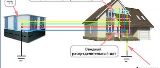
You have all seen small brick structures in the courtyards into which power cables enter and exit - these are transformer substations
(electrical installations). Transformer substations are used to receive, convert and distribute electrical energy. Any substation has a power transformer used to convert voltage, distribution devices and automatic control and protection devices.
Accepting high voltage network voltage 6 – 10 kV
(kilovolt) the substation converts it and transmits it to the consumer - that is, to us.
0.4 kV
or
400 Volts
goes to the consumer .
To power single-phase home equipment (TV, refrigerator, iron, computer, etc.), one of the three phases L1
;
L2
;
L3
and
neutral working
conductor “
N
”.
This is a standard scheme for providing consumers with electrical energy, on the basis of which additional schemes have been developed that differ in the method of connecting protective grounding, connecting and protecting electrical equipment, as well as the measures taken to protect people from electric shock
.
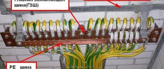
The transformer substation has its own ground loop
, to which all metal casings of the substation equipment are connected.
The grounding loop consists of metal rods driven into the ground, connected to each other by a metal bus using welding. This bus is called ground bus
.
The grounding bus is inserted into the substation building and laid around the perimeter of the building. Bolts are welded to it, to which through grounding conductors
All substation equipment is connected.
According to the PUE (Electrical Installation Rules), the grounding conductor ( neutral protective
) on electrical diagrams has the letter designation “
PE
” and color markings with alternating transverse or longitudinal stripes of yellow and green colors.
Loop elements, grounding options and required materials
Protective grounding systems (grounding devices) are usually divided into the following elements:
- ground electrode (ground loop); there is a natural and artificial option;
- grounding conductors.
According to the PUE, it will be preferable to use a natural ground electrode (metal fence or pipeline) if its resistance meets the established standards. Otherwise, it is allowed to use an artificial ground electrode. For its construction you need:
- Metal for the ground electrode (pipe, smooth fittings, steel angle, rod, tape).
- A wire made of steel, copper or aluminum of sufficient cross-section.
- Fastening material (metal corners, clamps, couplings).
- Fastenings and insulation made of plastic.
What does modular-pin grounding consist of Source ecoask.ru
Modular-pin grounding
The grounding loop of a country house can be organized based on the modular-pin method. The system is extremely resistant to corrosion; no welding is used during installation. Pin grounding is assembled from steel rods up to 1.5 m long with a threaded connection. Copper-plated (or with a top layer of stainless steel) pins are driven into the ground with a vibrating hammer (perforator) with a special attachment. The electrodes (pins) are mounted at a great depth, so the circuit parameters do not depend on seasonal changes. The kit is usually purchased ready-made from the organization that handles the installation. The high cost of such a circuit is justified by its durability: the service life of copper-plated rods reaches 30 years, and of stainless steel – 50 years.
Modular grounding kit Source tirez.ru
Black metal outline
This design has a limited service life (5-10 years, due to corrosion); Over time, the circuit resistance deteriorates significantly. It is permissible to use black rolled metal with an anti-corrosion coating, but care must be taken that such a coating is not dielectric.
Regulatory part
Grounding –
intentional electrical connection of any point in the network, electrical installation or equipment to a grounding device. [1] clause 1.7.28.
Protective grounding –
grounding performed for electrical safety purposes. [1].p. 1.7.29.
The operation of electrical networks with a voltage of 2-35 kV can be provided both with an isolated neutral and with a neutral grounded through an arc suppression reactor or resistor.
The operation of electrical networks with a voltage of 110 kV can be provided with both a solidly grounded and an effectively grounded neutral.
Electrical networks with a voltage of 220 kV and above must operate only with a solidly grounded neutral.[1] clause 1.2.16.
An artificial ground electrode is a ground electrode specifically designed for grounding purposes.[12] clause 1.7.16.
Natural grounding - a third-party conductive part that is in electrical contact with the ground directly or through an intermediate conducting medium used for grounding purposes.[1] clause 1.7.17.
Grounding devices of electrical installations with voltages above 1 kV in networks with an effectively grounded neutral should be carried out in compliance with the requirements for either their resistance or touch voltage, as well as in compliance with the requirements for design.[1] clause 1.7.88.
To exclude electrical connection between the external fence and the grounding device, the distance from the fence to the elements of the grounding device located along it on the internal, external or both sides must be at least 2 m.[1] clause 1.7.93.
What kind of lighting do you prefer?
Built-in Chandelier
A grounding device, which is carried out in compliance with the requirements for its resistance, must have a resistance of no more than 0.5 Ohms at any time of the year, taking into account the resistance of natural and artificial grounding conductors. [1] clause 1.7.90.
Horizontal grounding conductors should be laid along the edge of the territory occupied by the grounding device so that they together form a closed loop at a depth of 0.5 - 0.7 m. Vertical grounding conductors should be 3 - 5 m long. [1] clause 1.7.90.
It is believed that the resistances of natural and artificial grounding conductors interact in parallel.
If the grounding device is used simultaneously for electrical installations up to 1 kV and above 1 kV, then when choosing its resistance, the requirements for both voltage ranges should be taken into account, taking into account the mode of the electrical neutral.
Artificial grounding conductors can be made of black or galvanized steel or copper.
The material and smallest dimensions of grounding conductors must correspond to those given in table. 1.7.4. [1] clause 1.7.111.
a) Let us determine the required resistance of the artificial grounding electrode, taking into account the use of natural grounding electrodes.
Where is the resistance of the artificial ground electrode, Ohm;
— resistance of the natural ground electrode, Ohm;
Expert opinion
Viktor Pavlovich Strebizh, lighting and electrical expert
Any questions ask me, I will help!
A lower indicator of this soil characteristic will affect the hydrophilicity of concrete, powerful electrical resistance will occur, and the reinforced concrete structure will lose the properties of the ground electrode. If there is something you don’t understand, write to me!
Requirements for the resistance of the grounding device.
Grounding for a private home makes sense if the circuit resistance is minimal. In this case (when the human resistance is much greater than the resistance of the circuit), an imperceptible charge will pass through the body, and the remaining potential will go into the ground.
Resistance is determined by the type, quantity and depth of grounding elements, as well as the properties of the soil. Loamy and clayey soils with a moisture content of 20-40% are considered optimal.
To ensure that the grounding device is performing its functions, a resistance measurement is carried out.
Grounding switches
1.Natural
- water pipes laid in the ground (HW)
- metal building structures and foundations securely connected to the ground
- metal cable sheaths
— casing pipes for artesian wells
— gas pipelines and pipelines with flammable liquids
— aluminum shells of underground cables
— pipes of heating mains and hot water supply
The connection to the natural ground electrode must be in at least two different places.
Artificial
Contour
Remote: group and single
Allows you to choose a place with minimal soil resistance.
Traditionally, for artificial grounding conductors, angle steel with a flange thickness of at least 4 mm, steel strips with a thickness of at least 4 mm, or bar steel with a diameter of 10 mm or more are used.
Recently, deep-seated grounding electrodes with copper-plated or galvanized electrodes have become widespread, which are significantly superior to traditional methods in terms of durability and cost of manufacturing the grounding electrode.
Detailed information about various sealing schemes, calculation methods and consultations can be obtained on the website www.zandz.ru
What to do when replacing old TN-C ground wiring
Most of the older housing stock had a two-wire power supply system installed. Even if grounding was installed, it was carried out according to the TN-C scheme, which uses a single “neutral” conductor to perform two tasks - working (for the operation of electrical appliances and devices) and protective (for preserving electrical network equipment).
In essence, such a system reliably protects the electrical circuit as a whole, but leaves powered household electrical appliances and their owners practically without protection. In addition, in wet weather, such a connection can lead to voltage surges even during a protective shutdown - there have been cases of death for similar reasons.
PEN conductor separation diagram Source tirez.ru
When constructing new houses, this system is not allowed; where it has been preserved, it is recommended, if possible, to switch to the TN-CS system (at the entrance to the building, the PEN wire is re-grounded and subsequently divided into PE and N). In an emergency, conductor N is disconnected from the network, protecting household electrical appliances and their owners from problems.
The transition to a TN-CS system in houses with worn-out electrical wiring is justified for safety reasons.
Why do you need an RCD if there is grounding?
An RCD (residual current device) is a high-speed switch that works in tandem with a ground loop and responds to current leakage by breaking the circuit.
Operating principle of RCD Source tirez.ru
Circuit without grounding and RCD
When the insulation of a conductor is broken, a phase appears on the metal body of the electrical device. If the current has nowhere to go further, then when a person comes into contact with the body of an electrical device, the discharge will go through the body. The consequences will depend on many factors and the results can be different - from fear to interruptions in heart function.
Without grounding, the phase on the surface of the device with damaged wiring will remain until the input circuit breaker turns off .
RCD in a circuit without a protective conductor (TN-C)
In such a system, if the conductor insulation is broken, the RCD will not immediately operate, since no leakage current will occur. But as soon as a person touches the damaged device, part of the current will go into the body and the RCD will trip.
Even without grounding, current will flow through the human body only for the time required for the RCD to trip - usually tenths of a second. As a result, painful sensations are possible, but a fatal outcome can most likely be avoided.
Circuit with protective conductor (TN-S and TN-CS) and RCD
If an electrical appliance is in contact with the ground loop and is connected through an RCD, then if the phase conductor shorts to the metal body of the electrical appliance, leak immediately appears (which goes into the ground). The RCD trips and breaks the circuit.
Gas boiler and RCD
First of all, you need to understand that grounding a gas boiler in a private house must be carried out without fail - there are no exceptions.
Grounding the gas boiler and installing the RCD are carried out simultaneously. This is a necessary condition when connecting gas to a residential building, since surface tension forms on the body of the gas boiler during operation.
Grounding a gas boiler in a private home will avoid damage to expensive electronic equipment and prevent fire caused by static electricity. This measure, given the high explosiveness of the gas, serves as additional protection against fire.
All parts of a gas boiler must be grounded Source pinterest.com
What kind of work is done when installing grounding?
The entire process of creating a grounding loop is divided into the following stages:
- After determining the safe depth of the structure (where the soil is always wet), a trench is dug.
- Metal rods (grounding electrodes) are buried in the ground.
- A grounding loop is assembled: rods arranged in a row or in the shape of a figure (usually a triangle), connected with tape or pipes, and welded in series.
- The circuit is additionally welded to the down conductor with steel tape.
- The finished ground electrode is connected to the electrical panel, and the trench is backfilled.
During installation, competent specialists take into account some important nuances:
- The contour should be located below the soil freezing line. Otherwise, when the water in the ground turns to ice, the ground will stop conducting current and grounding will not work.
- Grounding electrodes cannot be painted, since the paint layer is a dielectric and there will be no contact of the circuit with the ground.
Grounding in a private house, circuit diagram Source asutpp.ru
Types of grounding
In the classification of types of grounding there are two main types:
There are several subgroups: radio grounding, measuring, instrumental, control.
There is a certain category of electrical installations that will not work unless they are grounded. That is, the main purpose of constructing a grounding system is not to ensure operational safety, but to ensure the operation itself. Therefore, in this article we will not be interested in this species.
But this type is specially arranged to ensure the safety of electrical installations. It is divided into three categories depending on its purpose:
- Lightning protection.
- Protection against surge voltage (overload of current consumption line or short circuit).
- Protection of the electrical network from electromagnetic interference (most often this type of interference is generated from nearby operating electrical equipment).
That is why, in order to eliminate such situations, the housing is grounded to a circuit located in the ground. At the same time, the activation of the grounding circuit is an impetus for the system of automatic machines, which immediately turn off the power supply to the equipment. All this is located in special power and distribution boards.
Ground resistance
There is such a term as resistance to current flow. For ordinary people it will be easier to perceive it as resistance to grounding. The whole point of this term is that the grounding circuit must work correctly within certain parameters. So resistance is the main one.
The optimal option for this value is zero. That is, it is best to use materials for assembling the circuit that have the highest electrical conductivity. Of course, there is no way to achieve the ideal, so try to choose those with the lowest resistance. These include all metals.
There are special coefficients that are used to determine the resistance of a grounding loop operated under different conditions. Eg:
Attention! If a grounding loop is used through the neutral of the transformer, then the resistance of the grounding circuit should be no more than 4 ohms.
- the installed gas pipeline system entering the house must be grounded with a 10 ohm circuit.
- lightning protection must have a resistance of no more than 10 ohms.
- Telecommunications equipment is grounded using a 2 or 4 ohm loop.
- Substations from 10 kV to 110 kV – 0.5 Ohm.
That is, it turns out that the greater the current power inside the equipment or devices, the lower the resistance should be.
What is the difference between vertical and horizontal grounding conductors?
The main thing is to make the correct connection of structural elements. By fastening the reinforcement of adjacent blocks together, you can verify the reliability of the structure, and then begin production of the grounding device.
Expert opinion
Viktor Pavlovich Strebizh, lighting and electrical expert
Any questions ask me, I will help!
Determining the situation when it is necessary to install a group of artificial rods is realized through special calculations. If there is something you don’t understand, write to me!