A floor switchboard is called a distribution switchboard and is intended for metering electricity and distributing it to consumers. Its task is to provide electricity to residential premises united on one floor. Modern electrical floor panels meet all requirements for load, number of lines, safety, they are able to ensure reliability in the supply of electricity to an apartment with any consumer devices.
The connection and installation of the floor panel is always carried out by professional electricians who have special permission to work with this electrical equipment.
Installation height of the shield in the apartment
Important information
Methods for ordering services:
Secretary:
Requirements for switchboard and distribution devices
Switchboard rooms are not allowed to be located under toilets, bathrooms, showers, kitchens, sinks, washing and steam rooms, laundry rooms, dry cleaners, etc. Pipelines and ducts laid through switchboard rooms should not have branches, hatches, valves, or flanges. The laying of gas pipelines and pipelines with flammable liquids, sewerage and internal drains through these premises is not allowed (clause 7.1.29 of the PUE). Panel doors must open outward. Switchboards must have natural ventilation and electric lighting, heating, providing a temperature not lower than +5 ° C (clause 7.1.30, PUE). Switchboard rooms must be equipped with protective equipment and first aid equipment in accordance with clause 1.1.36 of the PUE. The switchgear must have clear inscriptions indicating the purpose of individual circuits and panels on the front side of the device (clause 4.1.3 PUE). All metal parts of the switchgear must be painted (clause 4.1 PUE). The switchgear must be grounded (clause 4.1 PUE). Switching device drives must clearly indicate the “On” position. and "Off" (clause 4.1.11 PUE). The color designation of tires must comply with clause 1.1.29 of the PUE: the most distant one is yellow (A), the middle one is green (B), the closest one is red (C); in the vertical plane: A-B-C - from top to bottom or from left to right. DC buses: positive (+) - red, negative (-) - blue, zero operating (M) - blue. The most distant is M, the middle is (-), the closest is (+); in the vertical plane: M, (-), (+) from left to right or from top to bottom. A zero working tire is indicated in blue, if the same tire is used as a zero protective tire - blue along the entire length and stripes of yellow and green at the ends (clause 1.1.29 of the PUE). The color designations of the wires must comply with clause 2.1.31 of the PUE: blue - neutral working or middle conductor; green-yellow - protective or zero protective conductor; green-yellow with blue marks at the ends - combined zero working and zero protective conductor. Phase conductors: black, brown, red, purple, gray, pink, white, orange, turquoise. Apparatuses and instruments should be located so that sparks or electric arcs arising in them during operation cannot cause harm to operating personnel, ignite or damage surrounding objects, or cause a short circuit or ground fault (clause 4.1.8 of the Electrical Installation Regulations). If the input panel of a multi-panel ASU has two input blocks connected to different power supply networks, then they must be separated by a partition. A partition should also be provided between the ATS input devices (GOST R 51732-2001, clause 6.2.10). In single-panel and cabinet-mounted ASUs, input and distribution units should be separated by partitions (GOST R 51732-2001, clause 6.2.11). If one distribution panel of a multi-panel ASU contains two distribution units connected to different inputs, then a partition must be provided between them (GOST R 51732-2001, clause 6.2.12). It must be possible to relieve voltage from each switching device during its repair or dismantling. For this purpose, switches or other disconnecting devices must be installed in the required places (clause 4.1.12 of the Electrical Installation Code). Installation of instruments and devices on switchgear and low-voltage switchgears should be carried out in an area from 400 to 2000 mm from the floor level. Manual operational control devices (switches, buttons) are recommended to be installed at a height of 700 to 1900 mm from the floor level. It is recommended to install measuring instruments so that the scale of each instrument is at a height of 1000 to 1800 mm from the floor (clause 4.1.14 PUE). Between fixedly fixed non-insulated current-carrying parts, as well as between them and non-insulated non-current-carrying metal parts, distances of at least 20 mm along the insulation surface and 12 mm in the air must be provided. Distances of at least 40 mm must be provided from non-insulated live parts to the fence (clause 4.1.15 PUE). In electrical rooms, service passages located on the front or rear side of the switchboard must meet the following requirements: 1) the clear width of passages must be at least 0.8 m, the height of clear passages must be at least 1.9 m. The width of the passage must ensure comfortable maintenance of installation and movement of equipment. In some places, passages may be constrained by protruding building structures, but the width of the passage in these places must be at least 0.6 m; 2) the distances from the most protruding unfenced insulated live parts (for example, disconnected knife switches) when they are located on one side at a height of less than 2.2 m to the opposite wall, fence or equipment that does not have unfenced uninsulated live parts, must be no less than: 1.0 m - for voltages below 660 V for a board length of up to 7 and 1.2 m for board lengths of more than 7 m, 1.5 m - for voltages of 660 V and above. The length of the shield in this case is the length of the passage between two rows of a solid front of panels (cabinets) or between one row and a wall; 3) the distances between unfenced non-insulated live parts and those located at a height of less than 2.2 m when they are located on both sides must be at least: 1.5 m - for voltages below 660 V; 2 m - at voltage 660 V and above; 4) non-insulated live parts located at distances less than those given in paragraphs. 2 and 3 must be fenced. In this case, the width of the passage, taking into account the fences, must be no less than specified in paragraph 1; 5) unfenced, non-insulated live parts located above passages must be located at a height of at least 2.2 m; 6) fences placed horizontally above passages must be located at a height of at least 1.9 m; 7) passages for servicing shields with a shield length of more than 7 m must have two exits. Exits from the passage on the installation side of the switchboard can be made both into the switchboard room and into a room for other purposes. If the service passage width is more than 3 m and there are no oil-filled devices, the second exit is not necessary. Doors from switchgear rooms must open towards other rooms (with the exception of switchgears above 1 kV AC and above 1.5 kV DC) or outwards and have self-locking locks that can be unlocked without a key from the inside of the room. The width of the doors must be at least 0.75 m, height - at least 1.9 m (clause 4.1.23 PUE). Entrances to buildings must be equipped with a VU or ASU. Before entering the building, it is not allowed to install additional cable boxes to separate the service scope of external supply networks and networks inside the building. Such separation must be carried out in the ASU or main switchboard (clause 7.1.23 of the Electrical Installation Regulations). VU, ASU, main switchboard must have protection devices on all inputs of supply lines and on all outgoing lines (clause 7.1.24 PUE). Electrical circuits of VU, ASU, main switchboard, VRShch, distribution points, group panels should be made with wires with copper conductors (clause 7.1.31 PUE). After the meter, protection devices must be installed on the group lines (clause 7.1.65 of the PUE). A switching device must be installed in front of the meter to relieve voltage from all phases connected to the meter (clause 7.1.64 PUE).
Note! Open wiring in the apartment
Electrical panel assembly
When assembling it yourself, take into account that the machine at the entrance and the electricity meter are sealed by representatives of energy sales . If this is not possible, the entire shield will be sealed or acceptance will be refused. Inside the common electrical panel, a box is assembled into several places (depending on the type of machine), a switch is placed in it, which is sealed. The case is installed on the wall, and a DIN rail is fixed in it.
Step-by-step procedure for assembling the shield:
- fixing elements on the DIN rail according to the diagram;
- connecting modules to the input machine using a comb;
- connecting the phase wire with cables with lugs;
- installation of a zero bus;
- checking fasteners with a screwdriver;
- connecting current, checking operation;
- checking network indicators with a multimeter.
Before operation, make sure that all system elements (sockets, switches, distribution sockets, etc.) are installed and connected.
Connecting components
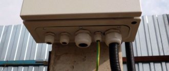
The shields have a place for cable entry, equipped with a cover. This is important when installing the housing in a niche, when the water supply is difficult. More often this is a group of perforated holes, the size of which is changed by removing the jumpers.
The cable is inserted into a corrugated pipe with a diameter of 16 - 20 mm. The mobility of wires in a pipe can be reduced by using plugs and gland plates. The wires are immediately marked, and the length in the box is left at double the height of the housing.
For connections, jumpers made of wire or bus are used; the first option is suitable for small boxes.
Tires are used in large cabinets , they compare favorably:
- good contact;
- reliability;
- neat look.
Valera
The voice of the construction guru
Ask a Question
Tires for the phase are gray, for zeros are blue, there are universal two-color ones that are used for two options. The working zero from the supply wire enters the zero bus, and then it is removed to circuits going to different rooms.
Connecting protective devices
RCDs and automatic devices are pressed against the DIN rail until a click appears. The wires are connected in accordance with the type of switch (single or double). After installing the devices, their inputs are connected. This is done with jumpers or combs.
Jumper installation:
- cut off pieces of wire of the required length, expose the edges, bend them in an arc, place 2 conductors in the terminal, tighten them;
- long wires are stripped of insulation by 1.5 cm every 5 cm, and the exposed areas are bent with pliers to obtain united arcs;
- areas without insulation are inserted into the sockets and tightened.
Along the phase line, the RCD is connected by dividing the wire into lighting circuit breakers, sockets, and powerful groups. The neutral line is connected after the fire protection. The neutral wire is fixed to a common neutral bus, then from it it is connected to all mounted RCDs and automatic circuit breakers.
Input devices, distribution boards, distribution points, group boards
7.1.22. A VU or ASU must be installed at the entrance to the building. One or more VU or ASU may be installed in a building. 
If there are several economically separate consumers in a building, it is recommended that each of them install an independent VU or ASU. 
The ASU is also allowed to supply power to consumers located in other buildings, provided that these consumers are functionally connected. 
For branches from overhead lines with a rated current of up to 25 A, the VU or ASU may not be installed at the inputs to the building if the distance from the branch to the group panel, which in this case performs the functions of the VU, is no more than 3 m. This section of the network must be carried out with a flexible copper cable with with a conductor cross section of at least 4 mm, flame retardant, laid in a steel pipe, and the requirements for ensuring a reliable contact connection with the branch wires must be met. 
For air input, surge suppressors must be installed. 
7.1.23. Before entering buildings, it is not allowed to install additional cable boxes to separate the service scope of external supply networks and networks inside the building. Such separation must be carried out in the ASU or main switchboard. 
7.1.24. VU, ASU, main switchboard must have protection devices on all inputs of supply lines and on all outgoing lines. 
7.1.25. Control devices must be installed at the input of supply lines to the VU, ASU, and main switchboards. On outgoing lines, control devices can be installed either on each line, or be common to several lines. 
A circuit breaker should be considered as a protection and control device. 
7.1.26. Control devices, regardless of their presence at the beginning of the supply line, must be installed at the inputs of the supply lines in retail premises, utilities, administrative premises, etc., as well as in consumer premises that are administratively and economically isolated. 
7.1.27. The floor panel must be installed at a distance of no more than 3 m along the length of the electrical wiring from the supply riser, taking into account the requirements of Chapter. 3.1. 
7.1.28. VU, ASU, main switchboard, as a rule, should be installed in electrical switchboard rooms accessible only to maintenance personnel. In areas prone to flooding, they should be installed above the flood level. 
VU, ASU, main switchboard can be located in rooms allocated in operational dry basements, provided that these rooms are accessible to maintenance personnel and are separated from other rooms by partitions with a fire resistance limit of at least 0.75 hours. 
When placing VU, ASU, main switchboards, distribution points and group panels outside electrical switchboard rooms, they must be installed in places convenient and accessible for maintenance, in cabinets with an enclosure protection degree of at least IP31. 
The distance from pipelines (water supply, heating, sewerage, internal drains), gas pipelines and gas meters to the installation site must be at least 1 m. 
7.1.29. Electrical switchboard rooms, as well as VU, ASU, main switchboards, are not allowed to be located under toilets, bathrooms, showers, kitchens (except for apartment kitchens), sinks, washing and steam rooms of bathhouses and other rooms associated with wet technological processes, except in cases where Special measures have been taken for reliable waterproofing to prevent moisture from entering the premises where the switchgear is installed. 
It is not recommended to lay pipelines (plumbing, heating) through electrical rooms. 
Pipelines (plumbing, heating), ventilation and other ducts laid through electrical switchboard rooms should not have branches within the room (with the exception of a branch to the heating device of the switchboard room itself), as well as hatches, valves, flanges, valves, etc. 
Laying gas and pipelines with flammable liquids, sewerage and internal drains through these premises is not permitted. 
Doors to electrical rooms must open outward. 
7.1.30. The premises in which ASUs and main switchboards are installed must have natural ventilation and electric lighting. The room temperature should not be lower than +5 °C. 
7.1.31. Electrical circuits within the VU, ASU, main switchboard, distribution points, group panels should be made with wires with copper conductors. 
Optimal diagram of a 380V electricity metering board for a private house 15 kW
It differs from the previous one in the presence of a selective Safety Shutdown Device (number 6), it works immediately for all consumers in the house, it is also called fire protection. The installation of an RCD at the entrance to the house is recommended by the Electrical Installation Rules - PUE.
Detailed step-by-step instructions for selecting equipment and assembly are available at this link...
Metering board diagram for a private house with selective RCD, For TT grounding system
This is the most balanced scheme that can be implemented for a remote electrical metering panel at home, simple and reliable. It is suitable for everyone, and this is what I recommend collecting.
To improve it, in order to enhance the protection of the electrical network and electrical appliances at home, you can add a surge protection device (SPD).
Pipelines
It is not recommended to lay pipelines (plumbing, heating) through electrical rooms.
Pipelines (plumbing, heating), ventilation and other ducts laid through electrical switchboard rooms should not have branches within the room (with the exception of a branch to the heating device of the switchboard room itself), as well as hatches, valves, flanges, valves, etc.
Laying gas and pipelines with flammable liquids, sewerage and internal drains through these premises is not permitted.
Doors to electrical rooms must open outward.
7.1.30. The rooms in which the ASU (input switchgear) and main switchboard (Group distribution board) are installed must have natural ventilation and electric lighting. The room temperature should not be lower than +5°C. 7.1.31. Electrical circuits within the VU (Input device), ASU (Input distribution device), Main switchboard (Group distribution board) of distribution points, group panels (apartment panels) should be made with wires with copper conductors.
That's all about installing an apartment electrical panel according to the rules! Good luck to you in your endeavors!
Purpose of equipment and importance of calculations
The main purpose of the distribution board is to protect the home electrical network from overloads, and the premises itself from fire
It is important to understand here that the design and calculations of all parameters must be carried out with the utmost care. For example, if the cross-section of the wiring is incorrectly calculated and the installation is of insufficient size, the load on the network can cause the insulating layer to burn
The other extreme is installing too powerful machines. In this case, electrical appliances with high energy consumption may cause the sockets to burn out.
For example, if the cross-section of the wiring is incorrectly calculated and the installation is of insufficient size, the load on the network can cause the insulating layer to ignite. The other extreme is installing too powerful machines. In this case, electrical appliances with high energy consumption may cause the sockets to burn out.
Wiring with a large cross-section that is not designed for specific conditions also leaves the network defenseless. During a load surge, protective actions may not occur because the circuit breakers will not have time to respond to critical indicators in time.
Approximate diagram of electrical panel constructionSource ul-avesta.ru
Purpose of the distribution panel
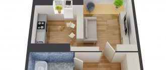
The distribution of power in an apartment building occurs according to the following scheme. From the transformer substation, the power supply cable is introduced into the house and connected to the input device (ID) and/or the main distribution board (MSB). From the input devices, the supply circuit “delivers” power to the floor panels, and from them, through distribution circuits, it “distributes” to the apartments where the apartment panels are powered. From the apartment panel, the power supply is distributed through group circuits throughout the apartment to sockets, lamps and stationary electrical appliances.
This is precisely the power supply scheme for an apartment originally, in ancient times, and remains in many old houses. According to old standards, distribution panels with fuses and a meter were installed in apartments, as in the photo.
Then the apartment panels were removed from the apartments, and the accounting and distribution of power supply to the apartments were concentrated in the floor panels.
In modern residential buildings, after the adoption of the new PUE edition 7.08.07.2002, apartment panels were “returned” to apartments. At the same time, the aluminum wiring was replaced with copper and all electrical wiring in the apartment acquired a more civilized appearance.
But not everyone lives in new houses, and the increase in electrical appliances in the apartment simply requires bringing the apartment’s electrical wiring into a modern, and most importantly, safe form.
Types of protective automation
Three types of devices are used in an electrical panel:
- circuit breakers;
- RCD;
- difavtomats.
The machine can operate in manual mode or be triggered when a short circuit occurs in the line. The switching device can be electronic or mechanical; it turns the electric current on and off when an abnormal current indicator occurs.
RCD is a protective device for breaking the circuit when a person touches live parts. The device monitors the leakage current that appears in this case. Protects against fire that occurs when electric current leaks through a faulty wire sheath.
The difavtomat combines an RCD device and a circuit breaker in a box, saving space in the distribution panel. The joint kit is more expensive and does not allow you to see the reason for the automatic blackout. There are models with a flag indicating the cause of the malfunction.
Choice for home and apartment
Based on the number of phases, an RCD is selected depending on the type of line - for single-phase they install the appropriate device, for 380 V they buy a three-phase one.
They produce RCDs with rated current values of 16, 25, 40, 63 A. Such indicators indicate the amount of current that the module will pass without turning off. The RCD is not equipped with overcurrent protection (overload, short circuit), so it is combined with a circuit breaker. The parameter is indicated on the back of the instrument housing.
Types of distribution boards
When changing or repairing electrical wiring in an apartment, the central link is the distribution panel. When choosing a distribution panel for an apartment, you need to understand that the panels can be mounted or built-in.
The hinged panel is installed on the wall. To install it, you do not need to carry out dirty and noisy work on the wall, which in some cases is a definite plus. The appearance of the hinged panel resembles a small cabinet. Modern hinged panels have a pretty good aesthetic appearance and despite the fact that the hinged panel takes up a lot of space on the wall, they are very often installed when replacing and repairing the electrical wiring of an apartment.
Testing and commissioning
After installation, they coordinate the operation of the electrical panel, check that the circuit breakers turn off when overloaded, and the RCD turns off when a leakage current appears. First, draw the contacts with a certain force.
Further work order:
- disconnect the load in the circuits (lights, sockets, household appliances);
- use a multimeter to determine that there is no short circuit in the network;
- the device checks the resistance of insulating shells to breakdown;
- check the ability to operate switching modules (diffautomatic devices, RCDs);
- Voltage is supplied to the switchboard and all circuit breakers and protective devices are turned on.
Valera
The voice of the construction guru
Ask a Question
To check, use the “test” key on RCD devices. The protective switches must be disabled, otherwise they must be replaced with serviceable ones. The test is carried out after pulling the mating contacts, since a weak connection may show a false insulation failure during the test.
Selecting a wall-mounted distribution panel
A mounted distribution board is selected according to the number of planned circuit breakers corresponding to the power supply groups in the apartment. Panels differ in the number of protection and control devices that can be installed in the panel. They are called modules.
Note: The module is a place in the panel for installing one single-pole circuit breaker. Accordingly, an RCD (residual current device) requires two modules, and a three-pole circuit breaker requires three modules.
If you have an electrical project for an apartment, then the type of panel can be viewed on a sheet with a single-line design diagram. Without a project, the master must tell you the number of modules in the panel. He must draw a diagram of the panel, on which the necessary protection and control modules of the electrical network will be visible. If you are doing the repairs yourself, then independently calculate the number of groups in the apartment (Read the article: Calculation of cable cross-sections, circuit breakers). Determine how many RCDs (residual current devices) are needed and determine the required number of protection and control modules in the panel.
Mounted panels are available with an even number of modules, starting from 6 pieces. A hinged panel with minimal space for modules is called a mini panel or mini box. Shields can be arranged with circuit breakers in one, two, three or four rows.
The configuration of the shields varies and depends on the manufacturer. Typically, the kit includes fasteners, DIN rails for installing circuit breakers (modular devices) and connecting blocks for connecting wires.
Note: A DIN rail is a metal plate with a special curved profile for convenient and quick installation of circuit breakers on it.
Mounted panels can be with or without a special place for the metering meter. With space for a meter or an already installed meter, hinged panels are called metering and distribution panels.
Also, hinged panels have either metal or plastic housings.
The degree of protection of the apartment panel must be at least IP31 (PUE 7.1.28, Link at the bottom of the article).
Note: IP is the degree of protection of an electrical device in accordance with the accepted international standard IEC 60529 (German: DIN 40050, Union: GOST 14254-96) shows under what external influences the device can operate properly. The maximum protection is IP 68, the minimum IP 22. For example, the incoming power supply device at home, for installation outdoors, must have a protection degree of at least IP 55. (You can read the article about the Input Device here)
Note! How to install electrical wiring in an apartment with your own hands?
Simultaneously with the selection of the hinged shield, you need to select a place for its installation.
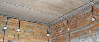
External wiring
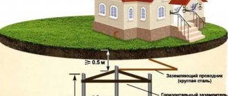
But in order to know how to properly install wiring in a private home, you should pay attention to the external electrical network. After all, a private house, in addition to a certain number of outbuildings, may have a fairly serious network of outdoor lighting. And for external networks, the rules have their own nuances.
- Wiring outside buildings can be installed via overhead or cable lines. Installing overhead lines in a garden plot is quite troublesome, and not very beautiful. Therefore, in most cases they resort to underground cabling.
To protect against mechanical damage, non-metal products should be used
- In this case, metal pipes or corrugation cannot be used to lay the cable. Clause 2.1.78 of the PUE categorically prohibits this method of installation. To protect against mechanical damage in this case, plastic corrugation or pipes should be used.
- But for laying not on the ground, but along the facade of buildings, the use of metal pipes or corrugations is not prohibited. Moreover, for facades of houses made of combustible materials, this installation method is mandatory. For fireproof building facades, it is allowed to perform an open installation method using plastic corrugation.
Wiring on the brick facade of the house
- In all cases, the mechanical protection of the wire or cable should be sealed and performed in such a way as to completely eliminate the possibility of moisture accumulation and ingress as in the video. This even applies to possible dew.
- If the wiring is connected to lamps installed at ground level, then in this case there must be a drainage system at the connection point. This should eliminate the possibility of moisture accumulation above the lamp itself.
- And in general, all electrical products and lamps must have appropriate protection. For outdoor installation, such protection must be no lower than IP44.
Place for installing a wall-mounted distribution panel
When choosing a location for installing a mounted distribution panel, I would recommend basing it on the PUE standards (Electrical Installation Rules chapter 7.p.7.1.28,35,36)
- The distance from the hinged panel to any pipeline in the apartment, including water supply, sewerage, heating pipes, must be at least 1 meter.
- The shield must be installed in a place convenient for maintenance.
- The height from the floor is recommended 1.5-1.6 meters to the meter window. If the panel is without a meter, the installation height is regulated only by ease of maintenance, usually 1.5-1.7 meters. True, when fighting for space, some install a hinged panel under the ceiling.
By the way, according to old standards, distribution panels with fuses were installed at a height of two meters from the floor. This is due to the provision of electrical safety measures. since these distribution panels did not have any external protection, but looked like an open panel with fixed fuses, “plugs”.
After choosing a place to install the mounted distribution panel, purchasing it and completing it, you can begin installation.
Advice from professionals
Now it would be useful to seek advice from professional electricians who will help you more competently connect the electrical panel and simplify its operation.
When installing a distribution board in an apartment or house, it is advisable to create a diagram of all connections with clear symbols. It can be drawn or printed on paper and glued to the inside of the panel housing door. This will allow, in the event of an emergency and the owner’s absence, almost anyone to quickly turn off or turn on the power.
For ease of maintenance and repair work, all wiring groups inside the distribution board are grouped according to the purpose of the lines. Grouping can be done using insulating tape or plastic clamps. Tags with appropriate inscriptions are attached to each group. When repairing wiring, you won’t have to rack your brains about which wire is responsible for what and avoid unpleasant mistakes.
Once again we remind you of the importance of correct connection of circuit breakers - the input conductors are inserted from the top. For reliability, inspect the markings on the devices; most manufacturers place on them a diagram of the correct connection and the question of how to connect the machine in the panel disappears by itself
Model shield
With proper assembly and calculations, there should not be an increased temperature. Otherwise, you need to turn off the shield and look for the source of the problem. If this is not done, a short circuit is inevitable.
Approximately once every six months it is necessary to tighten all the screws inside the distribution board
This is especially important when using aluminum wires in the network.
Professionals recommend not sparing three places for installing a modular socket in the panel. This will allow you to connect various tools and lighting to the panel, completely de-energizing all lines.
To create a high-tech distribution panel, it is recommended to install a voltage relay in it. This device will monitor network performance and, in the event of a critical surge or drop in voltage, will automatically turn off the load. After restoring the nominal parameters, it will turn on. In this way, you can reliably protect electrical appliances that have increased requirements for network voltage.
Outdated machines - “traffic jams” Once again, pay attention to the dimensions of the case, as mentioned above, it should be “expandable”, providing the possibility of expanding the system. A more spacious housing reduces mutual overheating of elements and increases their service life.
Pulling the contact fastenings can be combined with cleaning the inside of the switchboard housing. Dirt causes the shield elements to heat up more, and dust and cobwebs can become sources of short circuits.
Installation height of the shield in the apartment
This article provides rules and advice for connecting distribution boards based on the standards of the Republic of Belarus and Russia, and recommendations from the world's leading manufacturers of panel board products.
The electrical panel is the heart of your electrical installation. It is designed to house the devices and equipment needed to distribute all electrical circuits and protect people and property.
Selecting an electrical panel
Parameters for selecting a distribution board:
1. Type of installation. There are internal versions, for hollow or hollow walls (plasterboard) and external versions (attached to any base).
When choosing the type of electrical panel, pay attention to the material and design features of the walls of the room in which it will be installed. For example, in panel houses, it is practically impossible to install a built-in electrical panel of more than 12 modules without causing damage to the load-bearing walls. In such rooms, it is recommended to install panels either externally or internally for hollow walls, with a plasterboard structure.
2. Number of modules . For apartments and cottages, switchboards are used with the ability to install modular devices up to 63A. The number of modules determines the total number of electrical wiring lines and modular devices + a reserve of at least 20% (preferably 30%) is made for the possible connection of additional equipment in the future.
3. Degree of protection. For indoor installation, electrical panels with a degree of protection of IP30-IP40 are used, and for installation in unfavorable conditions (basement, bathhouse, open area), you should choose panels with a degree of protection IP44-IP65.
4. Material. Shields can be made of metal or plastic. In residential premises, it is better to opt for plastic panels, and in utility rooms (garage, workshop, etc.) it is better to use metal ones.
Electrical panels located in residential premises must have lockable doors (preferably metal ones). If there are children, the door must be closed with a locking device that does not allow a child to open it. Locking the apartment panel with a key is not recommended.
Electrical panel placement
For the input device for power supply and telecommunications, in residential premises it is recommended to provide areas in which the installation of an electrical panel, fire alarm and security systems, automation equipment, telecommunication networks (telephone, television, Internet, etc.) is carried out.
Centralizing various devices in one place allows for easier access and maintenance of various components necessary for the normal functioning of electrical equipment and low-current systems located in the same room.
Such zones should be located in the apartment itself or in the house (preferably at the entrance), in the garage or in an additional room (panel room).
Electrical panels can be installed both in specially prepared niches (internal installation) and on various fire-resistant bases (outdoor installation).
The shield is installed at a height ranging from 1 meter (lower edge) to 1.8 meters (upper edge). As an exception, the shield can be installed within 0.5 - 1.3 meters if elderly people or people with disabilities live in the room.
Installation of distribution boards (for an apartment or private house) is prohibited :
- In bathrooms and showers (outside and in hazardous areas 0, 1 and 2);
- In a closet or wardrobe;
- Above heaters;
- Under and above the sink or washbasin;
- Above the hob;
- Installation outside the home (including balcony or loggia)*
- In the toilet;
- On flights of stairs;
- In damp areas;
- In ventilation shafts;
*The distribution board should not be confused with the metering board, which can be installed at the border of a country house plot.
Selecting the cable cross-section for powering the electrical panel
The cross-section of the cable cores supplying the internal distribution board (apartment or house) depends on:
1. Voltage rating (220 or 380 Volts).
The electrical panel of the apartment in most cases is connected to a single-phase voltage of 220-230 Volts. Three-phase input, in apartments in Minsk, is very rare and practically never occurs.
In country houses, the best solution would be to connect to a three-phase voltage - 380-400 Volts.
2. The allocated power and rating of the main feeding machine (installed in a common floor switchboard or in a metering switchboard), as well as the distance between switchboards.
If the distance between the main supply circuit breakers (or switches) of the panels is no more than 30 meters, then the cable cross-section for single-phase power supply of the apartment panel can be determined from the table below:
If the distance between the main power supply circuit breakers (or switches) of the panels is more than 30 meters, then when choosing the cross-section of the cable cores, it should be additionally determined using tables (taking into account power and distance).
To quickly select the desired cable cross-section, taking into account the distance, the following table will help:
Which cable to choose?
To power the apartment panel, it is better to use a flame retardant cable (VVGngLS). To power a switchboard in a country house, you should use an armored cable laid in the ground (VBbShv or AVBbShv).
To switch wires inside the switchboard, single-wire wires PuV (formerly PV1) and multi-core wires PuGV (formerly PV3, PV4) should be used. PuV and PuGV are ideal for use when installing modular equipment in a switchboard. They do not propagate combustion, are resistant to environmental influences (within the temperature range: from -50 o C to +70 o C), the service life is at least 15 years.
Stranded wire (PugV), before connecting, should be crimped with special lugs (NShvI, etc.)
What cross-section of wire should I use when assembling the panel?
To connect power equipment in a distribution board (circuit breakers, differential protection), there is a European standard that requires the use of a certain wire cross-section, depending on the maximum current of the devices. This:
- 10mm 2 for maximum current 45A;
- 16mm 2 for maximum current 60A;
- 25mm 2 for maximum current 90A;
In practice, as a rule, it is used:
- 6-10mm 2 for maximum current 40;
- 10-16mm 2 for maximum current 63A;
Standards and regulations
Standards, rules and recommendations for the installation of electrical equipment and modular equipment in electrical panels:
- Each switchboard must have a technical passport, which must indicate the following data: name of the manufacturer and its trademark, mark of conformity, type designation, rated current of the shield, voltage and frequency, degree of protection, technical specifications, year of manufacture
- It is prohibited to lay cables or connecting lines under the Din-rail
- Recommended clamp tightening torque 2 - 3.5 Nm
- The metal body of the switchboard must be grounded
- The cable supply for connecting lines should be 1.5-2 times the height of the connected shield (but not less than 400mm) in length.
- The lines in the electrical panel and the installed equipment must be marked and their meaning indicated (for example, using stickers located below the equipment or in a table located on the inner door of the panel)
Let's discuss this article together:
Click to cancel reply.
Tips for choosing shield equipment
- It is advisable to install electrical circuit breakers with combined trip units of class B or C. If the combined “circuit breaker” is knocked out, you must first find and eliminate the reason why it worked, and then simply return the lever to the operating position, and the power supply will be restored.
- The optimal switching capacity limit of the “machine” should be at least 4500 amperes.
- It is desirable that in the floor panel the protective grounding conductor is divided into a neutral working conductor and a protective conductor.
It will not be superfluous if a diagram of it is placed on the panel door so that all the wires are marked and have the appropriate colors. This will significantly speed up and simplify the work when servicing electrical equipment.
Connecting and checking the floor panel
After the installation of the floor panel is completed, it is time to connect and check the equipment. A massive, or rather massive sequential switching on of all consumers and a thorough door-to-door check of the functionality of all sockets is carried out. If the equipment sparks, there is smoke, the circuit breakers turn off, the tester readings deviate from the norm, this means that the floor switchboards were connected incorrectly. It is necessary to check the switchboard contacts.
, floor boards
Conclusions based on the results of the work done
Now it makes no sense to talk about the amount of my financial expenses. Any costs always depend on the quality of the product, the manufacturer of the automatic protection elements and other parts required for assembly. I can only say one thing: the savings on specialist labor costs amounted to about 10,000 rubles. The whole job (I had no such experience) took a total of about 5 hours. Again, the amount saved can be many times greater. It largely depends on the region, average prices and salaries in the city. However, even saving a small amount is worth doing all the work yourself. And experience will never be superfluous.
The editors of Homius.ru invite home craftsmen and craftsmen to become co-authors of the “Stories” section. Useful first-person stories will not only be published on the pages of our online magazine, its authors will receive a small financial reward.
Next STORIES How I built a barbecue gazebo with my own hands: the experience of a Homius reader
General information
There are many types of such equipment on sale. Prices, sizes, materials of manufacture will be found for any buyer and purpose. But first you need to understand what this electrical installation component is.
Purpose of the mounting box
Most people, when buying such equipment, pay attention only to the appearance of the product.
How it will look in the surrounding environment is, of course, important. But first of all, such boxes must meet the following requirements: But first of all, such boxes must meet the following requirements:
But first of all, such boxes must meet the following requirements:
- All installation and maintenance work is carried out under conditions that meet safety conditions.
- Metal enclosures are grounded.
- The material of the box must withstand temperature fluctuations, precipitation of all types, and solar radiation.
Plastic boxes are safer and look more attractive than metal ones. Such electrical installation devices go by different names. Some call them meter cabinets, others call them boxes. There is no single standard, and manufacturers define products in their own way. However, they all must be practical and convenient.
Most support mounting internal components using a standard DIN rail, allowing you to mount the equipment yourself. In addition to the meter, it is installed by trained specialists after receiving permission from the supervisory company.
Features of the box design
According to the rules, all protective boxes suitable for installation must comply with security levels from IP 20 to IP 65. In addition to size and color, they can be:
- Open installation.
- Secret.
- For floor mounting.
- For inline location.
- Invoices.
- Solid or collapsible.
Quality requirements
Even for such a simple-to-manufacture device as a box for an electricity meter in an apartment or on the street, high-quality execution of all its components is important. This will enable the owner to take readings comfortably and safely
When purchasing a metal cabinet, you need to pay attention to the following points:
To make the box itself, steel with a thickness of at least 1.2 millimeters is used. Thin iron will not provide sufficient strength and long-term use. Practice shows that the door of such shields is the first to sag. This violates the tightness of the structure and threatens the destruction of electrical devices installed inside. Industrial production involves testing finished samples in installations that simulate the most difficult weather conditions. If they pass the test, this means that the quality of the paint application is good and the sample will last a long time. Large manufacturers guarantee a service life of up to 15 years. Availability of a locking device. An outdoor box for an electricity meter must be selected with a lock that can be locked with a key. Its design can be any, the main thing is that there is a seal between the metal of the door and the cylinder. The thickness of the constipation is also important. The hole must be sealed. If there is a window for data control, then a seal is also needed here. Fastening must be provided with screws or self-tapping screws, since even the best glue dries out and the glass falls out. The cabinet door must be grounded. Since the first touch falls on it, if it is energized, you can get an electric shock with its help. Except for the door, the entire body is grounded
It is best if several bolts are provided for these purposes. Particular attention should be paid to the quality of seals. They are made of plastic rubber in the shape of a ring. There should be no breaks in it to avoid leakage. Semicircular bends along the edges of the door and body ensure a tight fit of the sealing gaskets, and if they break, they prevent water from getting inside.
There should be no breaks in it to avoid leakage. Semicircular bends along the edges of the door and body ensure a tight fit of the sealing gaskets, and if they break, they prevent water from getting inside.
Final installation of the electrical panel. Connecting consumer groups
Pre-assembly and testing work allow you to install the electrical panel by placing it in a prepared niche, hanging it externally, and connecting groups of consumers. You should wait until finishing work is completed, which may contaminate the device, increase the humidity around it, or get it wet.
The procedure is as follows:
- Secure the installation process by excluding the supply of current to the equipment input. In an apartment building, it is worth hanging a special sign on the control panel or the distributor on the floor.
- Remove the protective cardboard or special cover, remove all contents from the box, take the wires out and secure them, and clean the case if necessary.
- Insert the DIN rails with installed modules inside, secure with screws or clamps.
- The protective and working zero busbars are mounted in standard places and insulated in a metal box.
- Zero protective, neutral and phase wires are divided into separate bundles, fixed with plastic clips, and the presence of markings is checked.
- The protective zero cables are attached to the PE bus; the additional length of the reserve is tightened with couplings.
- After entering, all groups of consumers from the protective bundle are connected in series, the ends of the multi-core wires are crimped with the NShVI tip, the rest are stripped with a stripper to 1 cm, the excess is cut off.
- Final marking before clamping into terminals using heat shrink tubing or cable markers.
- The metal door is connected with a green-yellow cable to the protective zero bus.
- Cables connected to the buses of group RCDs are separated from the working zero bundle and brought out into a separate bundle. They are connected to the appropriate bus with a right angle bend, they are stripped, marked and fastened as in the previous group.
- The location of the phase cables should be on the opposite side of the box from the zero side. If there are special niches in the box, they are inserted and secured, branches and bundles of wires are secured with ties.
- In accordance with the diagram, the necessary cables are inserted into each circuit breaker. Marked and trimmed as necessary, secured.
- The working zero and input phase are connected to an automatic switch or input load switch to the upper terminals.
- The correct installation and cable markings are checked according to the working diagram, and all terminals are tightened with a force of 0.8 Nm.
Conclusions and useful video on the topic
Video #1. Electrical panel assembly option:
Video #2. Assembly instructions and recommendations for a 72-module panel:
You can assemble the electrical panel yourself, but checking the installation and connection by a qualified electrician is mandatory. Without an appropriate conclusion, the organization supplying the house with electricity will simply block the line.
Would you like to talk about your own experience in electrical installation work? Do you have useful information that could be useful to independent novice electricians? Please write comments in the block below, post photos and ask questions about the topic of the article.
Regulatory documents and rules
The requirements for installing an electrical panel are specified in GOST 51321.1-2007. The panel is a switchgear operating under voltage up to 1 kW. Its features are discussed in Chap. 4.1. 7th edition of the PUE. The requirements for the ASU in a residential multi-storey building are specified in GOST 51732-2001, and for switchboards - in GOST R 51628-2000. Since the apartment electrical panel is a low-voltage switchgear and control device, you need to refer to GOST 51321.1-2007.
Basic requirements and installation rules
GOSTs and PUE indicate the correct way to connect the panel.
The standards note several points:
the presence of a complete circuit with the rating of the circuit breaker, the type and cross-section of the cable, installed and one-time power, protection parameters of the housing shell; installation of modules equipped with a nameplate inside or outside is permitted; mandatory affixing of the “Caution Voltage” sign in the form regulated by GOST R 12.4.026; selection of cable cross-section for laying inside according to the rating of the circuit breakers;
selection of wire insulation capable of withstanding an alternating current voltage of at least 660 V; protection of bolted connections from vibrations and short circuits with disc springs, controllers, spring washers, tips; assembly of neutral conductors on N and RE buses; connecting the REN wire to the RE panel; use of terminals to protect input and output wires; performing work using screwdrivers with slots for screw slots, tools with insulated handles; cable marking with colored PVC tubes - blue/light blue (working zero), yellow-green (protection zero), red/brown (phase); marking of N and RE bus contacts according to the serial numbers of protective circuit breakers; connection of one conductor per bus terminal N or RE; designation of outgoing cables with round (line voltage from 1000 V), square (voltage up to 1000 V), triangular (control) tags.
Which case is more reliable - metal or plastic?
Metal distribution panel in a wooden house
The apartment panel is available in metal and plastic casings. The choice of material depends on the project, design specifications and financial capabilities of the user.
The metal electrical panel has a number of features:
- reliable landing on protective zero;
- high anti-vandal characteristics;
- good fire resistance;
- installed on the street or in the entrance;
- moisture resistance class IP31 – IP54.
The disadvantage of a metal case is the need for grounding. The third wire will need to be brought out from the main power supply panel of the apartment.
Plastic electrical panel near the door in the hallway
The plastic case has the following characteristics:
- suitable for interior design;
- can be built into a special niche;
- resistance to wet environments;
- beautiful transparent or tinted door;
- excellent dust resistance.
If the insulation is poor, there is a risk that the plastic will ignite and cause a fire. In this case, it is better to purchase a box made of textolite.