Types and designs of grounding
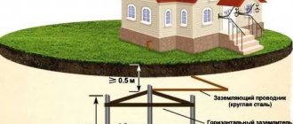
In private homes, PUE requirements allow the use of various types of grounding. The design of a conventional circuit includes vertical electrodes and one horizontal jumper. All elements must be the same size and have a circular cross-section. They are usually made from thick reinforcement, pipes or steel rods.
The classic figure is a ground loop with a triangle configuration, consisting of 3 reinforcing rods, measuring 2 meters or more. The greater the distance between the bars, the more efficient the system will work. The minimum distance is 1.5 m.
After the electrodes are driven into the ground, they are connected to each other. A separate strip is installed on each side, fixed at the same height. These are copper or steel horizontal grounding conductors installed on the top of the pins.
The place to install the circuit in a private house is chosen where people very rarely enter. Preference is given to the north side, which is poorly lit and helps retain a large amount of moisture in the soil. The distance from the contour to the wall of the house must be at least 1 meter.
In another embodiment, the grounding has a deep-type design. It has virtually no disadvantages characteristic of the conventional method, since a modular-pin system is used. The entire assembly kit, made at the factory, is technically confirmed by a certificate. The main advantage of these systems is their compliance with standards; they have an increased service life - from 30 years and above.
The electric charge spreads steadily, regardless of weather conditions. The depth of the electrodes reaches 30 meters, ensuring the quality and reliability of grounding, and the entire assembled circuit does not require constant checks.
Testing and evaluation
Afterwards, the ground loop must be connected and tested for resistance. To do this, we connect a multimeter to it in ommert mode, after which we connect all the devices in the room to grounding, and measure the frequency of the pulses. The optimal rate is 60 pulses per minute.
What are the requirements for the grounding circuit:
- It is allowed to choose more wires than indicated in our comparison table, but not less; The strip connecting the electrodes must be made of alloy steel, resistant to corrosion; The connections must be painted (the color is selected according to GOST);
The estimate is drawn up not only for the materials themselves; prices for a typical grounding loop also take into account the work being done, because in any case you will have to invite an employee of the electricity supply company to evaluate the work, he will fill out a passport and issue a protocol.
- Fittings - 1500 rubles; Steel tape and its installation - 3000 rubles; Painting of connections - 300 rubles; Primary documentation - 200 rubles; Welding work when connecting to a boiler room - 200 kW (100 rubles); Wires used to lay the grounding to the house wiring - 500 rubles;
The time frame for creating a circuit like a KTP or TP grounding is 3-5 days. The installation must be approached very responsibly, wear a protective suit and dielectric gloves, and use a mask when working with welding.
A modern private house is equipped with a large number of household electrical appliances. To connect them to the power supply, it is necessary to ground them for safety reasons. From this article you can learn how to properly make a ground loop in a private house with your own hands.
Connection diagrams
The most popular grounding connection schemes are:
Closed, in the shape of a triangle (Fig. 3). The main advantage is more stable and reliable operation. If the jumper between the rods is damaged, the circuit will still continue to work (but on the other side).
Rice. 3 Schematic diagram of a triangle
Linear (Fig. 4). Serial connection in one line of buried metal pegs. The disadvantage of such a circuit is that if the jumper fails, the circuit will not work.
Rice. 4 Schematic diagram of a linear view
In addition to the above types of contour diagrams, you can also use the following forms:
- rectangle;
- oval
Rice.
5 Shapes of ground loops Required tools and materials:
- welding machine;
- cutting tool (grinder);
- shovel;
- perforator;
- spanners;
- resistance meter;
- current meter;
- voltage meter.
In addition to the above devices, you must use:
- The corner is made of corrosion-resistant steel, its dimensions can be 50x50, 60x60 mm. Length – more than 2 meters. It is also possible to use a steel pipe with a diameter of at least 32 mm with a wall thickness of more than 3.5-4 mm.
- Metal strips (3 pieces). Their parameters: length – 120-130 cm; width – 4-6 cm; wall thickness – 4-6 mm.
- Steel strip made of stainless material 40x4, 50x5 mm. It connects the ground loop and the porch of the house.
- Bolts M10, M8.
- The conductor is copper, with a diameter of at least 6-7 mm2.
All the above parameters must be checked using a meter.
Which is better - homemade contours or a purchased kit?
To equip the grounding of a country house, you can buy a ready-made device kit. This will allow you to quickly install the structure, often without even the use of welding equipment. To connect individual elements, manufacturers make special fasteners.
Factory designs are considered more reliable because... All parts are made of stainless metal and are additionally treated with protective compounds. But they are expensive - from 7,000 to 10,000 rubles.
A grounding system assembled with your own hands from materials available at home allows the owners of a private cottage to save a lot of money. And if you correctly calculate the circuit and carry out the installation work efficiently, the homemade design will last no less than the factory one.
What is grounding
This is a complex consisting of metal structures and conductors, which ensures electrical contact of the electrical installation housing with the physical ground, that is, with the ground. The system begins with a ground electrode: a metal electrode grounded into the ground. These elements cannot be single; for reliability, they are combined into a grounding loop.
How it works
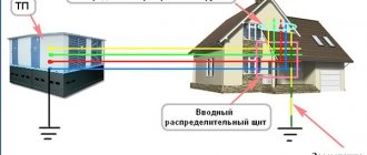
The external ground loop (which is located directly in the ground) is connected using a reliable conductor to the internal loop in the room, or to the grounding panel. Next, using an internal network of protective conductors, a connection is made to the housings of electrical installations and to the grounding contacts on switching devices (distribution boards, boxes, sockets, etc.).
Devices that generate electricity also have a grounding system to which the zero bus is connected. If an emergency occurs (a phase is connected to the electrical installation body), an electrical circuit arises between the phase conductor and the neutral bus along the ground line. The current strength in the emergency circuit spontaneously increases, the residual current device (circuit breaker) trips or the fuse insert burns out.
- the power cable does not ignite (fire hazard);
- The possibility of electric shock when touching the emergency housing of the electrical installation is prevented.
The resistance of the human body is tens of times higher than the grounding resistance. Therefore, the current strength (if there is a phase on the electrical installation body) will not reach a life-threatening value.
How to bring it into the house?
The ground loop is connected to the electrical panel through the metal strip that was used to connect the electrodes, as follows:
- You will need to dig a trench. The grounding circuit (diagram below) and the strip are welded to each other. After this, the strip must be extended to the electrical panel. To further connect the grounding bus to the electrical panel, a copper conductor can be used. Then a screw is welded to the grounding bus and connected to the copper conductor. A copper cable is connected to the screw using two washers and nuts, which collects all the grounding wires of the house.
What does grounding consist of?
- External ground loop. It is located outside the premises, directly in the ground. It is a spatial structure of electrodes (grounding conductors) connected to each other by an inseparable conductor.
- Internal ground loop. A conductive bus located inside a building. Covers the perimeter of each room. All electrical installations are connected to this device. Instead of an internal circuit, a grounding shield can be installed.
- Grounding conductors. Connecting lines designed to connect electrical installations directly to the ground electrode, or internal ground loop.
Take a closer look at these components.
External or outer contour
The installation of the ground loop depends on external conditions. Before starting the calculation and completing the design drawing, you need to know the parameters of the soil in which the ground electrodes will be installed. If you have built a house yourself, these characteristics are known. Otherwise, it is better to call surveyors to obtain an opinion on the soil.
What types of soils are there, and how do they affect the quality of grounding? Approximate resistivity of each soil type. The lower it is, the better the conductivity.
- Plastic clay, peat = 20–30 Ωm m
- Plastic loam, ash soils, ash, classic garden soil = 30–40 Ohm m
- Chernozem, shales, semi-hard clay = 50–60 Ohm m
This is the best environment to install an external ground loop. The current flow resistance will be quite low even with low moisture content. And in these soils the natural humidity is usually above average.
Semi-solid loam, mixture of clay and sand, wet sandy loam - 100–150 Ohm m
The resistance is slightly higher, but at normal humidity the grounding parameters will not exceed the standards. If there is prolonged dry weather in the installation region, it is necessary to take measures to forcibly moisten the installation sites of ground electrodes.
Clay gravel, sandy loam, wet (constant) sand = 300–500 Ohm m
Gravel, rock, dry sand - even with high general humidity, grounding in such soil will be ineffective. To comply with standards, deep grounding will have to be installed.
Many facility owners, saving on matches, simply do not understand why a grounding loop is needed. Its task, when connecting a phase to the ground, is to ensure the maximum value of the short circuit current. Only in this case will the protective shutdown devices operate quickly. This cannot be achieved if the current flow resistance is high.
Having decided on the soil, you can choose the type, and most importantly, the size of the ground electrodes. Preliminary calculation of parameters can be performed using the formula:
The calculation is given for vertically installed grounding conductors.
Decoding the formula values:
- R0 is the resistance of one ground electrode (electrode) obtained after calculation in ohms.
- Rekv - soil resistivity, see information above.
- L is the total length of each electrode in the circuit.
- d is the diameter of the electrode (if the cross-section is circular).
- T is the calculated distance from the center of the electrode to the surface of the earth.
By setting known data, as well as changing the ratio of values, you should achieve a value for one electrode of the order of 30 Ohms.
If the installation of vertical grounding electrodes is not possible (due to the quality of the soil), the resistance value of horizontal grounding electrodes can be calculated.
Therefore, it is better to spend more time driving vertical rods than to monitor the barometer and air humidity.
And yet we present the formula for calculating horizontal grounding conductors.
Accordingly, decoding of additional quantities:
- Rв is the resistance of one ground electrode (electrode) obtained after calculation in ohms.
- b - width of the electrode - grounding conductor.
- ψ is a coefficient depending on the weather season. The data can be taken in the table:
ɳG is the so-called demand coefficient for horizontally located electrodes. Without going into details, we get the numbers from the table in the illustration:
Preliminary calculation of resistance is necessary not only for proper planning of material purchases: although it will be a shame if you don’t have enough electrode to complete the work, and the store is several tens of kilometers away. A more or less neatly drawn up plan, calculations and drawings will be useful for resolving bureaucratic issues: when signing documents on acceptance of an object, or drawing up technical specifications with an energy sales company.
Of course, no engineer will sign papers only on the basis of even beautifully executed drawings. Spread resistance measurements will be taken.
How to do proper grounding at your dacha: the dangers of lack of grounding for your home
The construction of a private house or country house always involves a large amount of electrical work. In this range of tasks, along with supplying power to the house, installing distribution and protective equipment, laying internal lines, a well-planned and executed grounding system is no less important. Unfortunately, when carrying out self-construction, inexperienced owners quite often forget about this point or even deliberately ignore it, trying to achieve some kind of false savings in money and labor costs.
How to make grounding at the dacha
Meanwhile, the grounding system is of extreme importance - it can prevent many troubles that can lead to very sad or even tragic consequences. According to existing rules, electrical network specialists will not connect a house to a power line if this system is not in the house or if it does not meet the necessary requirements. And the owner, one way or another, will have to decide the question of how to make grounding at the dacha.
Expert opinion: Afanasyev E.V.
Chief editor of the Stroyday.ru project. Engineer.
In modern urban buildings, a grounding loop is necessarily provided at the design stage of the building and its internal communications. The owner of a private home will have to decide this issue himself - invite specialists or try to do everything himself. There is no need to be afraid - all this is a completely doable task.
Why is a ground loop needed?
In order to understand the importance of grounding, basic concepts from a school physics course are enough.
The vast majority of private homes are powered by a single-phase 220 volt AC network. The electrical circuit necessary for the operation of all devices or installations is provided by the presence of two conductors - actually, a phase and a neutral wire.
Typical wiring diagrams for a single-phase electrical network
The design of all electrical appliances, tools, household and other appliances includes insulation elements and protective devices that should prevent voltage from entering conductive housings or casings. However, the possibility of such a phenomenon can never be excluded - the insulation can be broken by a discharge, burn out from unreliable, sparking contacts in wire connections, circuit elements can fail, etc. In this case, phase voltage may reach the body of the device, touching which becomes extremely dangerous for humans.
Situations are especially dangerous if there are metal objects near such a faulty device that have so-called natural grounding - heating risers, water or gas pipes, open reinforcement elements of building structures, etc. At the slightest touch to them, the circuit can close, and a deadly current will pass through the human body towards a lower potential. Similar situations are no less dangerous if a person is standing barefoot or in wet shoes on a wet floor or ground - there are also all the prerequisites for shorting the alternating current circuit from the device body.
One of the expressed properties of electric current is that it will definitely choose a conductor with minimal resistance. This means that it is necessary to create in advance a line with minimal resistance and zero potential, along which, in the event of a breakdown on the housing, the voltage will be safely discharged.
The resistance of the human body is an unstable value, depending on individual characteristics and even on the temporary state of the person. In electrical engineering practice, this value is usually taken as 1000 Ohm (1 kOhm). Therefore, the resistance of the ground loop should be many times lower. There is a complex calculation system, but they usually operate with values of 30 Ohms for the household electrical network of a private house and 10 Ohms if the grounding is also used as lightning protection.
The RCD will work correctly only if there is a ground loop
It may be objected that all problems can be completely solved by installing special protective devices (RCDs). But for the correct operation of the RCD, grounding is also necessary. If even the slightest current leak occurs, the circuit will close almost instantly and the device will operate, turning off the dangerous section of the home electrical network.
Some owners are prejudiced that for grounding it is enough to use water supply or heating pipes. This is extremely dangerous and completely unreliable. Firstly, it is impossible to guarantee effective stress removal - the pipes may be heavily oxidized and may not have good enough contact with the ground, and in addition, they often have plastic areas. Electric shock cannot be ruled out when touching them in the event of a breakdown of the power supply to the housing, and neighbors may also be exposed to such a danger.
Plug and socket with grounding contact
Most modern electrical appliances are immediately equipped with a power cable with a three-pin plug. Appropriate sockets must also be installed when installing wiring in the house. (Some older model electrical appliances have a contact terminal on the body for a ground connection instead.)
Color marking of single-phase cable wires
There is a strictly defined color “pinout” of the wires: the blue wire is definitely “zero”, the phase can have different colors, from white to black, and the ground wire is always yellow-green.
And so, knowing this, some “wise” owners, wanting to save on updating the wiring and organizing full grounding, simply make jumpers in the sockets between the neutral contact and the grounding. However, this does not solve the problem, but rather aggravates it. Under certain conditions, for example, in the event of a burnout or poor contact of the working zero in some part of the circuit, or in the event of an accidental phase change, a phase potential will appear on the device body, and this can happen in the most unexpected place in the house. The danger of electric shock increases many times in such a situation.
Grounding is a reliable protection against many troubles
The conclusion from all that has been said is that grounding is a mandatory structural element of the home electrical network. It immediately performs the following functions:
- Effectively removes voltage leakage from conductive parts, touching which can cause electric shock.
- Equalizing the potential of all objects in the house, for example, grounded appliances and heating pipes, water supply, gas supply.
- Ensuring the correct operation of all installed safety systems and devices - fuses, circuit breakers or RCDs.
- Grounding is also important in preventing the accumulation of static charge on the housings of household appliances.
- It is of particular importance for modern electronics, especially computer technology. For example, the operation of switching power supplies for computers is very often accompanied by the induction of voltage onto the housing of the system units. Any discharge can lead to failure of electronic components, malfunctions, and loss of information.
Now that the importance of the grounding system has been explained, we can move on to the question of how to make it yourself in a private home.
Prices for protective automation
Protective automation
What are the types of grounding systems in private homes?
So, a well-executed grounding system should provide reliable contact with zero ground potential and with the minimum possible resistance of the created circuit. However, soil is different from soil - its different types seriously differ from each other in resistivity:
| Soil type | soil resistivity (Ohm × m) |
| Sand (for groundwater levels below 5 m) | 1000 |
| Sand (at groundwater level above 5 m) | 500 |
| Fertile soil (chernozem) | 200 |
| Wet sandy loam | 150 |
| Semi-solid or forest-like loam | 100 |
| Chalk layer or semi-hard clay | 60 |
| Graphite shales, clayey marl | 50 |
| Plastic loam | 30 |
| Plastic clay or peat | 20 |
| Underground aquifers | from 5 to 50 |
It is obvious that those layers that have the lowest resistivity are, as a rule, located at a considerable depth. But even when the electrode is deepened, the results obtained may not be enough. This problem can be solved in several ways - from increasing the installation depth of pin electrodes, to increasing their number, the distance between them, or the total area of contact with the ground. In practice, several basic schemes are most often used:
Possible grounding schemes in a private house
- Scheme “a” - installation of a recessed metal closed loop around the perimeter of the house. As an option - shallowly driven pins connected in a ring by a bus.
In dacha construction, it is used infrequently due to the large volume of excavation work or due to the peculiarities of the location of buildings on the site.
- Scheme “b” is perhaps the most popular among owners of suburban housing. Three or more moderately recessed pin electrodes connected by one busbar - this design is easy to make yourself, even in a limited space.
- Diagram “c” shows grounding with one electrode installed at a greater depth. Sometimes such a system is even installed in the basement of a building. The scheme is convenient, but not always feasible - it is almost impossible to implement it on rocky soils. In addition, for such a grounding system, you need to use special electrodes - we will talk about it below.
- Scheme “d” is quite convenient, but only if it was thought out at the stage of designing the house, and executed during the pouring of the foundation. It would be extremely unprofitable to implement it on a finished building.
So, the easiest way to implement schemes “b” or, if possible, “c” with minimal costs.
Grounding using homemade metal parts
To make a grounding system of this type, you will need metal profiles, a welding machine, excavation tools, and a sledgehammer. In some cases, with complex dense soils, a hand drill may be needed.
Schematically, this system looks like this:
The most commonly used grounding scheme for a private house
The location of the buried electrodes is chosen so that it is as convenient as possible to bring the grounding bus to the distribution panel. The optimal distance from the house is 3-6 meters. Acceptable limits are no closer than one meter and no further than ten.
The dimensions indicated in the diagram are by no means some kind of dogma. So, the side of the triangle can be up to three meters in length, and the depth of driving the pin can be slightly smaller - 2.0 ÷ 2.5 m. The number of electrodes can also change - if the soil is dense and it is not possible to drive the pins to a greater depth, you can increase their number.
A good idea is to contact your local utility company in advance for recommendations on how to install a ground loop. These specialists probably have well-thought-out schemes that have been tested in this region. In addition, they will be able to help calculate the dimensions based on the planned load of the home electrical network - this also matters.
Rolled metal that can be used for buried electrodes
What can serve as electrodes? For these purposes, a steel corner with a shelf of 50 × 50 mm and a thickness of at least 4 ÷ 5 mm is most often used. Pipes can be used, preferably galvanized ones with a wall thickness of at least 3.5 mm. You can take a steel strip with a cross-sectional area of about 48 mm² (12 × 4), but it is more difficult to drive it vertically into the ground. If you decide to use a steel rod, then it is also better to take a galvanized one with a diameter of at least 10 mm.
To tie the pins into one circuit, use a 40 × 4 mm strip or 12 - 14 mm wire rod. The same material is suitable for laying a grounding bus to the point of its entry into the house.
- So, initially markings are made at the selected location.
Pit and trench for ground loop
- Then it is advisable to dig a small pit of the intended shape to a depth of 1 meter. The minimum depth is 0.5 m. At the same time, a trench is dug to the same depth - a grounding bus will go along it from the contour to the base of the house.
You don’t have to dig a pit, but limit yourself to digging trenches
- The task can be somewhat simplified by digging not a solid pit, but only trenches along the perimeter of the contour being created. The main thing is that their width allows free driving of electrodes and welding work.
The edges of the corners need to be cut and sharpened so that they fit into the ground more easily.
- Electrodes of the required length are prepared. The edge with which they will be driven into the ground must be sharpened with a grinder, cutting it at an angle. The metal must be clean and unpainted.
The electrodes are sequentially driven into the ground to the required depth.
- At the designated locations, the electrodes are driven into the ground using a sledgehammer or electric hammer. They are buried so that in the pit (trench) they protrude above the surface level by about 200 mm.
Electrodes are connected by welding with a steel strip
- After all the electrodes are clogged, they are connected with a common busbar (horizontal grounding conductor) made of a 40 × 4 mm metal strip. Only welding is applicable here, although you can find recommendations to use a bolted connection. No, to ensure reliable and durable grounding, this harness must be welded - a threaded contact placed underground will quickly oxidize, and the circuit resistance will increase sharply.
The busbar is welded to the circuit and routed to the base of the building
- Now you can lay a bus from the same strip to the foundation of the house. The tire is welded into one of the clogged electrodes and placed in a trench, then it goes onto the base of the building.
- The busbar is attached to the base. Not shown in the figure, but it is advisable to provide a small bend in front of the attachment point, the so-called “compensation hump,” to compensate for the linear expansion of the metal during temperature changes. A bolt with M10 thread is welded at the end of the strip. A copper terminal with a grounding wire will be attached to it, which will go to the distribution panel.
Terminal transition to ground wire
- To pass the wire through the wall or through the base, a hole is drilled and a plastic sleeve is inserted into it. The wire used is copper, with a cross-section of 16 or 25 mm² (it is better to check this parameter with specialists in advance). It is also better to use copper nuts and washers for connections.
In this case, the grounding bus from the fittings is brought inside the room
- Sometimes they do it differently - a long steel pin is welded to the tire, so that it passes right through the wall of the house, also through the sleeve. In this case, the terminal part will be indoors and will be less susceptible to oxidation under the influence of high air humidity.
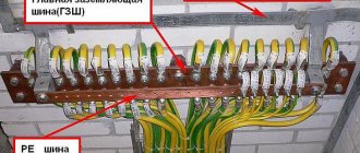
Bronze distribution plate for connecting ground wires
- The grounding wire is connected to the electrical distribution panel. For further “distribution”, it is best to use a special plate made of electrical bronze - all the grounding wires going to the points of consumption will be attached to it.
Upon completion of installation, it is necessary to check the functionality of the system.
Do not rush to immediately fill the installed circuit with soil.
— It is recommended, firstly, to capture it in a photograph with reference to surrounding stationary ground objects - this may be required to make changes to the design documentation, as well as to carry out control and verification activities in the future.
— Secondly, it is necessary to check the resistance of the resulting circuit. For these purposes, it is better to invite specialists from the energy supply organization, especially since their call, one way or another, will be necessary to obtain permits.
If the test results show that the resistance is high, it will be necessary to add one more or even more vertical electrodes. Sometimes, before checking, they resort to tricks by generously watering the areas around the corners hammered into the ground with a saturated solution of ordinary table salt. This will certainly improve the performance, however, do not forget that salt activates metal corrosion.
Ordinary table salt significantly reduces the circuit resistance, but, alas, activates metal corrosion
By the way, if it is not possible to hammer in the corners, then they resort to drilling wells to the required depth. After installing the electrodes, they are filled with clay soil as densely as possible, which is also mixed with salt.
After the functionality of the grounding loop has been checked, it is necessary to treat the welds with an anti-corrosion compound. The same can be done with the bus going to the building. Then, after the mastic has dried, the pit and trenches are filled with soil. It must be homogeneous, not littered and free of crushed stone inclusions. Then the backfill area is carefully compacted.
Video: installation of a grounding loop using a metal corner
Using ready-made factory kits
Ready-made factory-made kits are very convenient for organizing grounding at the dacha. They are a set of pins with couplings that allow you to increase the depth of immersion into the ground as you drive.
Single pin grounding system
This grounding system provides for the installation of one pin electrode, but to a greater depth, from 6 and even up to 15 meters.
The kit usually includes:
- Steel pins 1500 mm long with a galvanized or copper-plated surface, or made of stainless steel. The diameter of the pins may differ in different sets - from 14 to 18 mm.
Set of rods for assembling the grounding electrode
- To connect them, they are equipped with threaded couplings, and for ease of penetration through the ground, a steel tip is included in the kit.
Threaded coupling and ferrule for easy driving
In some kits, the couplings are press-fit rather than threaded. In this case, one end of the ground rod is tapered by forging and has a ribbed surface. When impacted, a strong connection occurs and reliable electrical contact is achieved between the rods.
The pins can also have a press-fit coupling
- To transmit the impact, a special attachment (dowel) made of high-strength steel is provided, which will not be deformed by the impact of the hammer.
Dowel - a nozzle that will transmit the impact force from the hammer
- Some kits include a special adapter that allows you to use a powerful hammer drill as a driving tool.
Hammering the electrode using a hammer drill
To install such a grounding system, it is also advisable to dig a small pit up to a meter deep and the same in diameter, although some even prefer external placement.
Growing the electrode as it is driven into the ground
The pins are driven in sequentially and incrementally to the required depth.
Then a brass contact clip is put on the area left on the surface (about 200 mm).
Either a metal bus or a ground wire can be inserted into such a contact clamp
Either a conductive busbar made of a metal strip is inserted into it, or a grounding cable with a cross-section of 25 square meters is inserted. mm. For connection to the steel strip, a special gasket is provided, which does not allow for electrochemical contact between the ground of the rod and the steel (zinc). Subsequently, the bus or cable is brought into the house and connected to the distribution panel in exactly the same way as described above.
Video: manually driving pin electrodes
Prices for components for lightning protection and grounding
Components for lightning protection and grounding
What type of rod coating should I choose – galvanized or copper-plated?
- From an economical point of view, galvanizing with a thin layer (from 5 to 30 microns) is more profitable. These pins are not afraid of mechanical damage during installation; even deep scratches left do not affect the degree of protection of the iron. However, zinc is a fairly reactive metal, and while protecting the iron, it oxidizes itself. Over time, when the entire zinc layer has reacted, the iron remains unprotected and is quickly “eaten up” by corrosion. The service life of such elements usually does not exceed 15 years. And making the zinc coating thicker costs a lot of money.
Comparative test: galvanized (left) and copper-plated (right) electrode after 10 years of operation in an aggressive acidic soil environment
- Copper, on the contrary, without reacting, protects the iron it covers, which is more active from a chemical point of view. Such electrodes can serve for a very long time without compromising efficiency; for example, the manufacturer guarantees their safety in loamy soil for up to 100 years. But during installation, care should be taken - in places where the copper plating layer is damaged, a corrosion area will likely appear. To reduce the likelihood of this, the copper plating layer is made quite thick, up to 200 microns, so such pins are much more expensive than conventional galvanized ones.
What are the general advantages of such a set of grounding systems with one deeply placed electrode:
- Installation is not particularly difficult. No extensive excavation work is required, no welding machine is needed - everything is done with ordinary tools that are found in every home.
- The system is very compact; it can be placed on a tiny “patch” or even in the basement of the house.
- If copper-plated electrodes are used, then the service life of such grounding will be several tens of years.
- Thanks to good contact with the ground, minimal electrical resistance is achieved. In addition, the efficiency of the system is practically not affected by seasonal conditions. The level of soil freezing accounts for no more than 10% of the length of the electrode, and winter temperatures cannot in any way negatively affect the conductivity.
There are, of course, some disadvantages:
- This type of grounding cannot be implemented on rocky soils - most likely, it will not be possible to drive the electrodes to the required depth.
- Perhaps some will be put off by the price of the kit. However, this is a controversial issue, since high-quality rolled metal for a conventional grounding scheme is also not cheap. If we also add the duration of operation, simplicity and speed of installation, and the absence of the need for specialized tools, then it is quite possible that this approach to solving the grounding problem may seem even more promising from an economical point of view.
Video: how to ground your home using a modular pin system
Grounding calculation for a private house: formulas and examples
Grounding calculations for a private home are based on formulas for calculating the resistance to current spreading for electrodes. Examples will be shown below.
Soil resistance
For a single rod, the formula is applied:
where ρ eq is the equivalent resistivity of a single-layer soil (selected according to Table 1 for a specific soil);
- L—electrode length (m);
- d—electrode diameter (m);
- T is the distance from the middle of the electrode to the ground surface (m).
Table 1
Dimensions and distances for ground electrodes
The number of electrodes in the circuit can be calculated using the formula, where:
Rн is the maximum permissible total circuit resistance (for a network of 127-220 V - 60 Ohms, for 380 V - 15 Ohms), Ψ - climatic coefficient (determined according to Table 2).
table 2
Electrode sizes are selected taking into account actual conditions and recommendations:
- pipe - minimum wall thickness 3 mm, diameter - depending on the availability of material;
- steel bar - diameter not less than 14 mm;
- corner - wall thickness 4 mm, size - according to the availability of material;
- strip for linking electrodes - width - at least 10 mm, thickness - more than 3 mm.
The depth of penetration (length of the electrodes) is selected from the condition - at least 15-20 cm below the freezing level. The minimum length is 1.5 m. The pin installation step is 1-2 times the length of the electrode, and the minimum distance is 2 m.
Watch this video on YouTube
Instructions for circuit design
- The AC ground loop device must be installed at a distance of about 50 meters from the point where electrical networks enter the house. This distance is optimal for installing both vertical and horizontal electrodes, but preferably their surface should not be painted; The cross-sectional profile of the grounding conductors is selected according to the material, we have prepared a special table from which the dimensions of the electrodes are selected; A table from which the dimensions of the electrodes are selected is drawn up from a steel angle and a steel strip, their connections are carried out by arc welding, after completion of the work it is necessary to test the strength of the connections;
Installation of a closed circuit is carried out as follows: a trench of the selected depth is dug, the optimal value is 70 centimeters, but if your apartment is filled with various types of power plants, then you can create a ditch up to a meter down. The shape of the trench is an isosceles triangle with a maximum width of a meter and a depth of about 07-1 m; it must first be measured.
Outline triangle
A corner is hammered into the vertices of the triangle with a sledgehammer, which will be responsible for the initial resistance of the ground loop of a private house.
The optimal pipe length for a regular building is 2-3 meters. If the reinforcement does not fit into the ground well, use a special drill, not a hammer. After this, we begin to install our grounding conductors along the trench.
Tips from an electrician:
- Before you make a protective grounding loop with your own hands, you need to sharpen the ends of the pipes, so they will be easier to install and there will be no need for repeated force; The corners should not be hammered in completely, but should be left about 30 centimeters above the surface of the ground. This will help connect them. Scheme for hammering in the corners. After we weld the parts of the system into one whole, and connect the house or electrical panel to the voltage input; The places of welding and bends must be treated with degreasers and special anti-corrosion solutions. There is another way to connect the tape and electrodes - remove an additional one from the ground a closed wire, to which, using medium-sized bolts, connect the conductors along which we will lay the buses. The cross-section of the copper cable for this method must be at least 10 mm, aluminum - 16 mm, steel 75 mm.
After all the electrodes are closed, you need to lay a steel strip up to 4 mm thick, starting from the substation and moving around the perimeter.
You will need a drawing diagram of the site, because...
installation of a ground loop for a private house or building is prohibited by SNIP over gas or water pipes. It can be drawn up schematically or using software (for example, the AutoCad program), this document will be needed when the inspection protocol is drawn up in accordance with GOST. In addition, you also need to take into account the permission from the energy supply company.
Video: how to make a ground loop in a house
Grounding loops can be constructed only if there is an act for hidden work.
Circuit design
Components
The previously mentioned grounding resistance (Rз) of the circuit is the main parameter controlled at all stages of its operation and determines the effectiveness of its use. This value must be so small as to provide a free path for the emergency current tending to flow into the ground.
Note! The most important factor that has a decisive influence on the value of grounding resistance is the quality and condition of the soil at the site of the installation. Based on this, the charger in question or the ground loop of the charge circuit (which in our case is the same thing) must have a design that meets the following requirements:
Based on this, the charger in question or the ground loop of the charge circuit (which in our case is the same thing) must have a design that meets the following requirements:
- It must include a set of metal rods or pins with a length of at least 2 meters and a diameter of 10 to 25 millimeters;
- They are connected to each other (necessarily for welding) by plates of the same metal into a structure of a certain shape, forming a so-called “grounding conductor”;
- In addition, the device includes a supply copper busbar (also called electrical) with a cross-section determined by the type of equipment being protected and the magnitude of the drain current (see the table in the figure below).
These component devices are necessary to connect the elements of the protected equipment with the descent (copper busbar).
Differences in device location
According to the provisions of the PUE, the protective circuit can have both external and internal design, and each of them is subject to special requirements. The latter establishes not only the permissible resistance of the ground loop, but also stipulates the conditions for measuring this parameter in each particular case (outside and inside the object).
When dividing grounding systems according to their location, it should be remembered that only for external structures the question of how the grounding resistance is normalized is correct, since it is usually absent indoors. Internal structures are characterized by wiring of electrical busbars along the entire perimeter of the premises, to which grounded parts of equipment and devices are connected through flexible copper conductors.
For structural elements grounded outside the facility, the concept of re-grounding resistance is introduced, which appeared as a result of the special organization of protection at the substation. The fact is that when forming a neutral protective conductor or a working conductor combined with it at the supply station, the neutral point of the equipment (step-down transformer, in particular) is already grounded once.
Therefore, when another local grounding is made at the opposite end of the same wire (usually a PEN or PE bus connected directly to the consumer panel), it can rightfully be called repeated. The organization of this type of protection is shown in the figure below.
Important! The presence of local or repeated grounding allows you to insure yourself in case of damage to the protective neutral wire PEN (PE - in the TN-CS power supply system). Such a malfunction is usually found in technical literature under the name “zero burnout”
Such a malfunction is usually found in technical literature under the name “zero burnout.”
Grounding schemes: which one to choose
The grounding system of a country cottage depends on the type of network connection to it. The TN-C principle is often used. At a voltage of 220V, the mains voltage is provided by an overhead two-wire line or a two-wire cable. At 380V, a four-wire line or four-wire cable is used.
TN-CS
In this case, the PEN input is divided into parallel conductors.
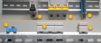
The PEN conductor, located in the input cabinet, is divided into 3 buses:
- neutral – N;
- earth - RE;
- distributor for 4 connections.
The N bus is placed on insulators, the PE is connected to the body of the input cabinet. The conductors do not contact each other. A circuit is connected to the distributor. The ground electrode is connected by a copper jumper with a cross-section of 10 mm² to the N bus.
TT
In this case, the tires are not split in the input panel, because neutral and ground are already separated in the network. Only the PE conductor is connected to the ground electrode.
Standards of PUE grounding
Grounding PUE standards are a set of regulatory legal acts. These rules include recommendations on how to carry out electrical wiring correctly, a description of various electrical installations and the principle of their operation, as well as the requirements for electrical systems and their components.
Grounding installation work must be carried out in accordance with the electrical installation regulations. The criteria defined in the PUE will allow all connections to be made without errors, maintaining all standards. This guarantees reliable operation of the protective system in the house and will avoid the negative consequences of natural and man-made impacts.
If you unquestioningly follow all the rules described in the PUE, this will lead to large financial costs, so electricians and engineers follow only very important recommendations in their activities.
In accordance with the rules of the PUE, a repeated protective circuit must certainly be located at the exit areas from the premises. It is recommended to install natural grounding electrodes at this location. These include reinforced concrete devices, large metal parts, which for the most part are directly connected to the ground.
The PUE also specifies items that cannot be used as grounding conductors: energized metal objects, sewer and heating pipes, as well as pipelines with flammable substances.
When installing grounding, it is necessary to carefully carry out calculations, taking into account all the factors affecting the quality of the device being created, and it is necessary to follow the PUE.
Grounding into the shield
The distribution board is installed on the wall of the building, and the installation site must be protected from moisture. The cables are routed through the wall using special pipe sleeves. The wire is connected to the busbar installed on the panel body using a bolted connection.
After installation, the grounding is checked with a multimeter. The number of electrodes increases with resistance exceeding 4 ohms. Ground wires in yellow insulation are connected to the corresponding ground bus connector. When connecting various devices - lamps, open-mounted sockets with grounding and others - the yellow wires are also connected to the corresponding terminals. For example, on sockets such a terminal is located in the center. Hidden sockets with grounding are considered the safest - they are used to connect refrigerators, gas stoves and other household appliances.
Grounding switches
1.7.109. The following can be used as natural grounding electrodes:
1) metal and reinforced concrete structures of buildings and structures that are in contact with the ground, including reinforced concrete foundations of buildings and structures that have protective waterproofing coatings in non-aggressive, slightly aggressive and moderately aggressive environments;
2) metal water pipes laid in the ground;
3) casing pipes of boreholes;
4) metal sheet piles of hydraulic structures, water conduits, embedded parts of valves, etc.;
5) rail tracks of main non-electrified roads and railways and access roads in the presence of a deliberate arrangement of jumpers between the rails;
6) other metal structures of structures located in the ground;
7) metal shells of armored cables laid in the ground. Cable sheaths can serve as the only grounding conductors when there are at least two cables. Aluminum cable sheaths are not allowed to be used as grounding conductors.
1.7.110. It is not allowed to use pipelines of flammable liquids, flammable or explosive gases and mixtures, and sewerage and central heating pipelines as grounding conductors. The specified restrictions do not exclude the need to connect such pipelines to a grounding device for the purpose of equalizing potentials in accordance with 1.7.82.
Reinforced concrete structures of buildings and structures with prestressed reinforcement should not be used as grounding conductors, however, this restriction does not apply to overhead line supports and outdoor switchgear support structures.
The possibility of using natural grounding conductors based on the density of currents flowing through them, the need for welding reinforcing bars of reinforced concrete foundations and structures, welding anchor bolts of steel columns to reinforcing bars of reinforced concrete foundations, as well as the possibility of using foundations in highly aggressive environments must be determined by calculation.
1.7.111. Artificial grounding conductors can be made of black or galvanized steel or copper.
Artificial grounding conductors should not be painted.
The material and smallest dimensions of grounding conductors must correspond to those given in Table 1.7.4.
1.7.112. The cross-section of horizontal grounding conductors for electrical installations with voltages above 1 kV should be selected according to the condition of thermal resistance at a permissible heating temperature of 400 °C (short-term heating corresponding to the duration of the protection and tripping of the circuit breaker).
If there is a risk of corrosion of grounding devices, one of the following measures should be taken:
increase the cross-sections of grounding conductors and grounding conductors, taking into account their estimated service life;
use galvanized or copper grounding conductors and grounding conductors.
In this case, one should take into account the possible increase in the resistance of grounding devices due to corrosion.
Trenches for horizontal grounding conductors must be filled with homogeneous soil that does not contain crushed stone and construction waste.
Grounding electrodes should not be located (used) in places where the ground is dried out by the heat of pipelines, etc.
Carrying out the calculation of the protective circuit
The ground loop resistance should be determined by determining several values:
- Determine the resistivity of the soil on the site.
- Determine soil moisture.
- Soil salinity level.
- Average temperature in the region.
- Distance from the foundation to the contour.
- Dimensions of grounding conductors and other parts of the device.
The calculation method is “simple” - you need to know many physical formulas and have an engineering education. But, as a rule, no calculation method can take into account all the values. Therefore, after installing the external ground loop and measuring the value of the protection resistance, you will see that the calculation does not coincide with the actual result.
For this reason, a standard design is being carried out for installation in this region; all that remains is to make changes, taking into account the distance of the device from the building. And then they measure the circuit resistance, make changes until the nominal resistance value is reached, no more than 4 ohms in residential construction.
Therefore, by choosing the best scheme, observing all the dimensions and depth of driving the grounding conductors, selecting high-quality material, it will not be difficult to do the job correctly for your home. And it is necessary to calculate grounding for large industrial and commercial buildings.
Types of material (profiles)
According to the requirements of the PUE, which contain instructions on what the resistance of current flow in the ground should be, in most cases this indicator is set at a level of no more than 4 ohms. To obtain this value, you usually have to make a lot of effort to adhere to the same technology requirements.
First of all, this concerns the materials used in assembling the grounding loop, selected based on the following conditions:
- When choosing pins, preference should be given to ferrous metal blanks;
- The most commonly used rod is a standard size of 16-20 mm or a corner with parameters 50x50x5 mm and a metal thickness of about 5 mm;
- It is not allowed to use reinforcement as circuit elements, since it has a hardened surface that affects the normal flow of current;
- For these purposes, it is pure rod that is suitable, and not its reinforcement substitute.
Note! For areas with dry summers, thick-walled metal pipes are best suited, the lower end of which is flattened into a cone, and then several holes are drilled in this part of the pipe. According to the provisions of the PUE, before placing them in the ground, holes of the required length are first drilled, since driving them manually is quite problematic
In the case of a particularly dry summer and a sharp deterioration in the parameters of the ground electrode, a concentrated saline solution is poured into the hollow parts of the pipes, which makes it possible to obtain the resistance that should be in accordance with the requirements of the PUE. The length of pipe blanks is selected within 2.5-3 meters, which is quite enough for most Russian regions
According to the provisions of the PUE, before placing them in the ground, holes of the required length are first drilled, since driving them in manually is quite problematic. In the case of a particularly dry summer and a sharp deterioration in the parameters of the ground electrode, a concentrated saline solution is poured into the hollow parts of the pipes, which makes it possible to obtain the resistance that should be in accordance with the requirements of the PUE. The length of pipe blanks is selected within 2.5-3 meters, which is quite enough for most Russian regions.
This type of profile blanks has special requirements regarding the order of their placement in the soil and consists of the following:
- Firstly, the pipe elements of the protective circuit must be placed at a depth exceeding the soil freezing level by at least 80-100 cm;
- Secondly, in particularly dry areas, approximately a third of the length of the ground electrode should reach wet soil layers;
- Thirdly, when fulfilling the second condition, one should focus on the peculiarities of the location of the so-called “groundwater” in a given region. If they are located at a significant depth, according to the rule formulated in the provisions of the PUE, it will be necessary to prepare longer pipe sections.
The type and profile of the pin blanks used in the construction of the grounding switch can be found in the figure below.
In practice, in most regions of Russia, a steel corner and a strip of the same metal are usually used. In order to obtain more accurate parameters of the grounding elements used, geological survey data will be required. If this information is available, it will be possible to involve specialists in calculating the parameters of the ground electrode.
Electrode connection
The pins are connected to each other by a strip of 40x4 millimeters. Rolled ferrous metal is welded because the bolts quickly corrode, which leads to an increase in the resistance of the overall circuit. Welding seams must be of high quality.
From the assembled circuit, grounding is carried out in a strip to the house and attached to the foundation. The wire from the shield is connected to a bolt welded to the edge of the strip.
The fastening clamp is installed on the last electrode, after which the wire is secured. The clamp is sealed with a special tape.