Reasons for the popularity of wire trays
First of all, these trays are more affordable. The advantages of these structures also include the low cost of their installation. Without touching on the material component, the advantage of this type of tray is also its high level of electromagnetic compatibility. Another definite plus is the provision of high-quality cable cooling. Other reasons for the relevance of wire trays include:
- no need to use additional expensive accessories;
- no dust on the surface of the trays;
- high level of load capacity.
Subtleties of grounding from PUE that everyone forgets about
Grounding in apartments is carried out centrally, so the owners of such housing do not need to come up with something and rack their brains about where to get grounding in an apartment building. Things are completely different with private housing, where the arrangement of the ground loop falls entirely on its owner.
Rule #1
However, you should not worry about this, because it is enough to read paragraph 1.7 of the PUE to understand that both natural and artificial grounding conductors can serve as grounding. What does it mean?
Let's say there is a concrete or steel structure somewhere close to your house that has enough area to serve as a ground electrode. This is exactly what can be used to protect electrical appliances.
In addition, for reliability, you can measure the grounding to understand how well the structure performs its task. When measuring grounding, it is important that its resistance does not exceed 30 Ohms. Otherwise, grounding will do a poor job of protecting electrical installations.
Rule #2
It goes without saying that using water or gas pipes as grounding conductors is not a good idea. This is directly stated in the PUE (section 1.7.110). “It is not allowed to use pipelines as grounding conductors, including for central heating and sewerage.”
It’s another matter if it is an old pipeline that is without pressure and has not been used for a long time. Also, many people use a well casing pipe, which goes 10 meters or more into the ground, as grounding conductors. In any case, it should be an unused pipeline, since grounding causes the metal to deteriorate over time.
Rule #3
Also, when installing grounding, many people wonder what exactly should be the cross-section of the conductors coming from the grounding conductors. The Electrical Installation Rules also answer this question.
Thus, it is allowed to use copper protective conductors with a cross section of 2.5 and 4 mm². If the cable does not have mechanical protection, then its cross-section must be at least 4 squares. If there is mechanical protection against damage, it is allowed to use a copper conductor with a thickness of 2.5 mm².
Rule #4
It states that grounding is in no way connected to the working zero. That is, zero is zero, and grounding is grounding. It is unacceptable to connect these two conductors together; neutral and ground go separately.
Grounding trays using PUE - All about electricity
In order to commission cable routes, it is necessary to take various measures to improve the safety of the equipment. One of these measures is the grounding of cable trays. This process must be given special attention in order to do everything correctly and in accordance with GOST standards. It should also be noted that cable trays come in many different types, so the connection method is different.
They can be wire, sheet, perforated and all-metal. We will talk about how to ground each of the design options below.
Grounding
Using a cable tray system as a protective PE conductor
Trays can be connected to each other using 3 types of connectors:
Ratio of initial (transition) resistance, contact connection of elements
trays to the resistance of the entire section of the tray is no more than 2, which satisfies the requirements of GOST 10434-82 “Electrical contact connections”. The hardware used for assembling trays (boxes), namely an M6x10 screw with a wide head and an M6 nut with a locking shoulder, provide a reliable electrical connection, stabilized according to class 2 (GOST 10434-82).
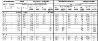
The tray is connected to the potential equalization system (the main grounding bus of the ASU) by a conductor secured using standard hardware or welding (GOST 10434-82). The cross-section of this conductor is determined based on the short circuit currents of the phase conductors to the tray according to the method outlined in clause 1.7.126 of the PUE, since in the case of a short circuit of the phase conductor to the tray (box), the short circuit current will flow not only through the protective conductor, but along the tray (box). The required cross-section of the protective conductor is determined by the formula:
where Is is the short-circuit current that ensures the shutdown time (t) of the damaged circuit by the protective device, in accordance with the standard according to 1.7.79 PUE (for distribution networks t ? 5 s, for group networks t ? 0.4 s); k is a coefficient, the value of which depends on the material of the conductor, its insulation, initial and final temperatures (before closing and after disconnecting the damaged section of the circuit).
For the convenience of consumers, the maximum short circuit currents that the tray (box) and its connectors can withstand have been determined. The current flow time was determined as t? 0.2 s (according to GOST R 50030.2-2000). These currents are shown in the table.
Determining the point of connection of the wire to the highway
To determine the point of connection of the wire to the potential equalization system, you should be guided by the provisions of the “Instructions for lightning protection and construction of grounding networks.” According to the data specified in this instruction, the connected sections of trays, profiles, cable blocks and other electrical wiring elements must form a continuous electrical circuit. Moreover, they must be connected to the highway in at least two places - at the beginning and at the end. If the length of the electrical wiring structures does not exceed two meters, then it is possible to connect the wire in only one place.
To summarize, it should be said that for grounding cable trays made of wire, you should use PVZ-4 mm² wire. Grounding terminals must be installed along the entire route. In this case, the wires must be connected to the EMS.
Metal connection of trays
All trays are connected to each other using screws. The result is a continuous structure with normal strength and rigidity. There is also a certain metal connection between the sections, due to which electric current can flow through the trays.
However, simple structural connections are clearly not enough for them to be used as a grounding conductor. This requires additional jumpers installed in certain locations, or the trays themselves must be connected accordingly, ensuring reliable grounding of the entire box.
The insulation of standard jumpers is marked with an established combination of yellow and green colors. As a rule, these are conductors with copper conductors with a cross section of 4-6 mm 2. If these elements are manufactured independently and a flexible wire consisting of stranded wires is used, in this case its ends must be crimped. Connecting screws used in conjunction with jumpers must not be used for other purposes, for example, as fastenings.
The set of screw connections of the grounding device includes nuts and washers that prevent the fasteners from loosening. Sometimes the sets are equipped with special busbars made in the form of small copper plates. It should be remembered that the design of the tray is complemented by a removable cover, which is not included in the grounding system and is not taken into account when designing it.
Use of Grounding Materials
Grounding cable channels and using metal boxes as a conductor is permissible if there is permission in the technical passport of the facility.
Operation of the structure is possible subject to the following conditions:
- each element of the cable support line has a good galvanic connection;
- the cable route has no interruptions;
- the quality and functionality of the design are checked in a timely manner by specialists;
- along the length of the structure, all elements are connected taking into account the requirements of regulatory documents;
- the required cross-sectional area of the trays is provided along the entire route line.
After the start of operation, it is important to carry out timely inspections of the grounding system and check it for serviceability. It is important that the inspection is carried out by a specialist - this will help increase the safety of the structure. To use a cable tray as a PE conductor, it is necessary to calculate the short circuit, and then select elements of grounding equipment.
It is also better to entrust this process to a specialist who has detailed information about the object and can adequately assess the design features. Next, the minimum separation of the PE conductor is determined according to the rules describing the grounding of trays according to the PUE.
To complete the calculations, you will have to compare the minimum indicator of the PE conductor with the cross-sectional areas of the main communication line along the entire route.
Requirements of rules and regulations
In this case, the laying of power cables requires compliance with the PUE (Chapters 2.1., 2.3, for example, clauses 2.1.15 and 2.1.16, clauses 2.3.122-2.3.133), SNiP (3.05.06-85), a number of relevant state standards, and must also be produced according to a carefully developed project. The main task of the specialists who will install wires on trays and boxes is to strictly follow the drawings of the electrical wiring installation project. The designer must take into account all the rules and regulations, select a tray based on design features, material, and IP protection rating.
In addition, according to GOST, it is necessary to develop a plan for laying cables in boxes (that is, will they run as single cores, tied into bundles, etc.). After this, the appropriate design documentation is drawn up to obtain permission to carry out work on installing the power cable from the necessary authorities.
Only specific organizations that have all the necessary documents allowing them to carry out this work can have access to such projects.
Simple grounding scheme
The design of the wire tray creates the effect of a “Faraday cage” - it prevents electrical waves from escaping: thus, not only the contents are protected, but also what is outside it.
Wire systems, like any other, must be connected to a potential equalization system (EPS). But since their connection points do not provide the necessary conductivity, it is necessary to take additional measures - installing an additional control system at the ground terminals.
They are mounted to the walls every 10-20 meters and a copper wire with a cross-section of 4 mm is passed through. At the connection points it must be bare, the insulation removed. The ends of the wire on both sides are connected to the potential equalization system: thus, there must be at least two terminals in the design.
An exception is for trays less than 2 meters long - here one terminal can be connected. Thus, a single continuous electrical network is obtained.
The “rule of two connections” was originally prescribed in the grounding rules for explosive objects, where wires are not used. But the opinion of experts is that additional security measures never hurt. Open conductive parts of structures and neutral protective conductors are connected to the additional control system.
The tray can also be used as a protective conductor if this is provided by the manufacturer in the design and technical documentation. Then the system must be installed in a place where it is completely insulated and protected from mechanical damage.
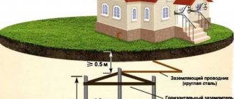
Ring ground electrode
A flat wire made of galvanized or stainless steel (30x3.5 mm, 40x4 mm), a round electric copper wire (8 mm), a round wire made of galvanized or stainless steel (10 mm) can be used as a grounding electrode. The ground electrode made from the above materials is laid in the form of a ring around the perimeter of the architectural structure at a distance from the foundation of at least one meter and to a depth of at least half a meter. When laying, at least 80% of the grounding conductor must be in the soil. All elements of the general electrical system of the building, as well as cable trays and wire boxes, are connected to one ring grounding conductor.
Deep ground electrode
The deep ground electrode is made of the same materials, but is located vertically in the ground, not along the perimeter of the building. Depending on the class of lightning protection and grounding of electrical boxes for laying wires or cables, the depth of location is determined. The ground electrode is placed at a distance of at least one meter from the foundation of the building to a depth of 2.5 to 9 meters. When installing lightning protection, the number of grounding conductors is determined by the number of down conductors from the lightning rod.
When installing a classic grounding system, several down conductors can be connected to one ground electrode. If there are several deep ground electrodes around the building, they must be additionally connected to each other.
Foundation ground electrode
As the name suggests, this type of ground electrode is located directly inside the concrete foundation of a building or structure, or, in other words, the reinforcement of reinforced concrete piles or a flat foundation is used as a ground electrode. This type of grounding must be provided at the design stage. For already constructed objects, the implementation of foundation grounding of metal cable ducts and trays is not possible or difficult to implement.
Requirements for conductors
When installing grounding, as well as protective grounding, steel cable sheaths of any class or armor are connected to the charger through copper conductors of a standardized cross-section. This requirement also applies to coupling or end coupling housings. On lines designed to transmit high-voltage power (6 kV and above) and having an aluminum sheath, coupling grounding is performed with separate conductors.
For this purpose, it is prohibited to use copper conductors with a conductivity greater than the corresponding indicator for cable sheaths.
The general requirements of current standards provide for the use of bare copper conductors with a cross-section of at least 6 mm square. The same parameters for control cables are specifically stipulated in the PUE (see clauses 1.7.76-1.7.78).
If the support of the air supply to the electrical installation is equipped with end couplings containing arresters, their housings are connected directly to the protective device charger. The use of cable sheaths alone in this capacity is not allowed in this situation. Special overpasses and galleries used to accommodate explosive cables must be equipped with protection against lightning discharges and lightning.
When moving from an underground laying line to a section of its overhead wiring and if the reinforced concrete support does not have its own charger, the couplings are allowed to be grounded to the cable armor. This approach is permissible only if the repair or extension coupling at the other end is connected to the station grounding circuit, or if the resistance value of the sheath of the grounded cable is sufficiently small.
Removable tray covers
When installing a cable route, you must take into account that the tray covers are not part of this structure, so they should not be grounded. For the reason that the removable cover with grounding initially has an excellent level of protection against electric shock. The products provided by DSK are installed very simply and quickly.
For installation, you just need to choose the best method: by drilling holes in the wall, or using hangers. Each surface of this design has special contours and additional accessories. To fix the grounding wire, you can use an M5 bolt.
It is required to approach this work correctly and constructively, because thanks to this you can be confident in protection from electric shock in the event of a short circuit, which is immediately transmitted to the base body.
The importance of using removable lids
When arranging cable routes, it is important to remember that removable tray covers do not require grounding, like the rest of the structure. This became possible due to the high level of protection of these products from the negative effects of current.
High-quality removable covers for trays can be easily installed using hangers or mounted directly on the wall. On top of these parts there is a coating in the form of a grounding loop. The wire for grounding the trays is fixed quite simply using an M-5 class bolt. Ultimately, grounding metal trays prevents electric shocks from short circuits.
The use of removable covers for trays is also convenient because they can be quickly mounted and removed without additional equipment. Therefore, additional cables can be added to existing cable channels at any time.
In addition, this element allows you to quickly inspect the structure during a breakdown. As a rule, such covers are made from sheet metal and have different widths, which makes it easier to select the necessary parts and install them on the appropriate tray.
Conditions of use
The use of metal trays and boxes as PE-type conductors is only possible if there is permission in the technical data sheet of the design. This requirement is specified in Chapter 1.7 of the PUE. Operation is possible if the following conditions are met:
- there are no interruptions along the entire cable route;
- along the entire line, the required cross-sectional area of the trays and their connections along the entire length is ensured;
- line elements have high-quality galvanic connections;
- specialists promptly check the grounding of the perforated tray and the quality of fixation of connections.
To use a cable tray as a PE conductor, a number of requirements must be met. First, the short circuit current is calculated. Having correctly completed all the calculations, it becomes possible to optimally select elements of grounding equipment. Accurate calculations can be carried out by a specialist who has information about the parameters of the cable route.
Then the minimum cross-section of the PE type conductor is calculated. Here you should also use the recommendations of the rules for constructing electrical installations given in the PUE. Next, you need to compare the minimum cross-sectional area of a PE type conductor with the cross-sectional area of all elements that are present in the cable-supporting complex. This should be done along the entire route.
Peculiarities
On the territory of Russia there are specialized rules and standards. According to them, elements that can be quickly installed and removed do not require additional grounding. However, if there are special requirements, a special cover can be installed on the grounding tray. In this case, it is possible to install additional jumpers and grounding conductors that have sufficient galvanic connection. For example, the company DKS produces such products.
All conductive cable lines should be connected to a potential equalization system. In the case of ladder and sheet trays, things are a little better. The peculiarity is that wire trays cannot provide sufficient conductivity. As a result, it is important to provide a number of additional measures for connecting to the potential equalization system.
For example, the DKS company recommends creating connections every twenty meters. However, experts recommend doing this every ten meters. Such grounding is usually used if the structure is operated under more severe conditions.
To fully connect wire trays, it is recommended to use special grounding terminals. They can be found at any local market. The installation technology is quite simple. All you have to do is attach the terminal to the wall of the tray, and then pass the wire through it. At the point where the wire comes into contact with the terminal, you should remove the insulation. As a result, the grounding of metal trays becomes more efficient. The conductor can be a PVZ wire, which has a yellow-green insulation color.
Metal connection of trays
Cable trays are classified as conductive, therefore it is mandatory to ground metal cable trays to protect against electric shock if accidentally touched.
This measure is especially relevant when large volumes of cables and wires are used. In this regard, grounding must be installed in at least two places on the main route, and always at one point where the branch line ends. All trays are connected to each other using screws. The result is a continuous structure with normal strength and rigidity. There is also a certain metal connection between the sections, due to which electric current can flow through the trays. However, simple structural connections are clearly not enough for them to be used as a grounding conductor. This requires additional jumpers installed in certain locations, or the trays themselves must be connected accordingly, ensuring reliable grounding of the entire box.
The insulation of standard jumpers is marked with an established combination of yellow and green colors. As a rule, these are conductors with copper conductors with a cross section of 4-6 mm2. If these elements are manufactured independently and a flexible wire consisting of stranded wires is used, in this case its ends must be crimped. Connecting screws used in conjunction with jumpers must not be used for other purposes, for example, as fastenings.
The set of screw connections of the grounding device includes nuts and washers that prevent the fasteners from loosening. Sometimes the sets are equipped with special busbars made in the form of small copper plates. It should be remembered that the design of the tray is complemented by a removable cover, which is not included in the grounding system and is not taken into account when designing it.
Wire trays
Advantages of wire trays
If we compare this version with other products, wire trays have quite a lot of positive features, here are some of them:
- installation is not too expensive;
- the products themselves are much cheaper than sheet products, as well as ladder types;
- wire cooling is much better than in designs with closed boxes;
- in order to ground the tray, you can use a fairly simple circuit;
- Very little dust accumulates inside, several times less than in galvanized or metal structures;
- in terms of load indicators, cable trays made of wire are not inferior to others, for example, sheet trays;
- There is no need to buy expensive additional accessories to use it.
It will take very little effort to ground the cable tray, because it initially has excellent electromagnetic compatibility. Products made from polyvinyl chloride are not able to provide high-quality interference suppression. Because of this phenomenon, metal cable trays produced by the DKS company began to be widely used by cellular operators.
According to the PUE, it is mandatory to ground all trays. The conductive supporting structure for the wires requires complete, comprehensive protection. And the work itself is carried out in full compliance with the standards that are in SNiP. For example, DKS brand trays are grounded at least at two points - at the beginning and the end.
Wire channels for laying cables are conductive and therefore need to be connected to a potential equalization system. Unlike the connections found in tape and sheet channels, wire trays have less contact and therefore less conductivity. For this reason, a special terminal is used, which ensures the required resistance value between the cable system and the ground bus.
Features of wire structures
Along with conventional structures, wire trays are also widely used as grounding and can be connected to potential equalization systems. The main difference between these products and conventional trays is a significantly smaller contact area, so they accordingly have lower electrical conductivity.
In such cases, it is necessary to ensure the necessary resistance indicators in the area between the grounding device and the wire cable route. For such purposes, the grounding of the wire tray is supplemented with special grounding terminals.
Subject to these additional measures, wire structures begin to noticeably outperform conventional products in terms of their performance:
- The cost is significantly lower than standard designs. With large volumes of work, large savings in money are obtained.
- Installation is easy and quick, without any special physical or material costs.
- Cooling of cables occurs faster than in conventional trays.
- Dust hardly accumulates inside the structure and can be easily removed during line maintenance.
- Possibility of using relatively simple grounding schemes.
- Subsequent operation does not require the purchase of any additional high-cost elements.
- Wire grounding structures can withstand loads just as well as standard trays.
The grounding of wire cable trays itself is quite easy, since the structure itself has good electromagnetic compatibility. Thanks to the so-called Faraday grid effect, electromagnetic interference is effectively suppressed, which is completely impossible when using PVC structures.
Grounding of cable trays: elements, requirements and application features
At the stage of commissioning cable routes, electricians take some measures to increase the safety of the equipment. Such actions include grounding cable trays.
There are many types of trays, differing in the type of grounding. The most common type of trays is wire. They must be installed in accordance with the conditions set out in GOSTs and PUE (Electrical Installation Rules).
Some inexperienced users feel that connecting trays with screws ensures cable continuity. However, reliable metal communication, which is judged by voltage conductivity, is not achieved in all electrical installations. The route refers to grounding conductors only if there are additional jumpers or in the case of connecting trays according to certain standards. The connection requirements are set out in GOST 10434-82.
To simplify orientation in the grounding system, the jumpers should correspond to a certain color scheme. Most often we are talking about a combination of green and yellow colors. The cross-section limits are set from 4 to 6 square millimeters.
When organizing grounding using self-made jumpers, one should not forget about an important rule: the ends must be processed. Processing means crimping. The screws for fixing the protective conductors cannot be used to solve other problems, for example, for joining the tray end or mounting on a support.
In some product modifications, screw hardware for trays are equipped with washers or nuts. These elements have a “scratching” surface. Thanks to this feature, more reliable electrical contact is ensured, since the risk of loosening fasteners is significantly reduced. Small copper plates are also used (they are also called busbars).
Requirements of rules and regulations
In this case, the laying of power cables requires compliance with the PUE (Section 2), SNiP (3.05.06-85), a number of relevant state standards, and must also be carried out in accordance with a carefully developed project. The main task of the specialists who will install wires on trays and boxes is to strictly follow the drawings of the electrical wiring installation project. The designer must take into account all the rules and regulations, select a tray based on design features, material, and IP protection rating.
In addition, according to GOST, it is necessary to develop a plan for laying cables in boxes (that is, will they run as single cores, tied into bundles, etc.). After this, the appropriate design documentation is drawn up to obtain permission to carry out work on installing the power cable from the necessary authorities.
Only specific organizations that have all the necessary documents allowing them to carry out this work can have access to such projects.
Grounding trays to each other PUE
Before putting cable routes into operation, specialists take a number of additional measures to increase the safety of the equipment. One such measure is grounding cable trays. Since there are different types of trays, differences can be found in the grounding process. In particular, this applies to wire types.
In any case, the installation must comply with the regulatory requirements of GOST standards and electrical installation rules.
Grounding
Currently, work is underway in Ukraine to improve the level of electrical safety in electrical installations of residential and public buildings.
An important stage of this work is the improvement and streamlining of the requirements of regulatory documents, especially in the field of standardization of electrical installations.
In a group network, those laid from group panels to electrical receivers must be made of three wires (Phase - L, zero working - N and zero Protective - PE conductors). It is prohibited to combine zero working and zero protective wires of different group lines. The neutral working and neutral protective conductors are not allowed to be connected on the panel under a common contact terminal. The cross-section of conductors must meet the requirements of PUE clause 2.5.15
To use the cable tray system as a PE conductor, the trays and accessories are connected to each other using male-female connectors or using connecting plates and secured with M6x10 screws with a wide head and M6 nuts with a locking collar. This connection provides a reliable electrical connection, stabilized according to the second class (GOST 10434-82).
The connection of the cable tray system to the potential equalization system (main grounding bus) is carried out with a conductor secured using standard hardware or welding (GOST 10434-82). The cross-section of this conductor is determined based on the short circuit currents of the phase conductors to the tray according to the methodology set out in the PUE clause 1.7.126.
If a phase conductor is short-circuited to a tray, the fault current will flow not through the protective conductor, but through the tray. When the cross-sections of the connectors connecting the elements of the cable route system and the conductor connecting the tray to the main grounding bus are smaller than the cross-section of the tray, the maximum withstanding short-circuit current is determined by the minimum cross-section, provided that this current is sufficient to trigger the instantaneous release of the circuit breaker.
- For partners
- Product Catalog
- Feedback
- Contacts
- Search
© Copyright 2004-2020 TM SCaT Copyrights are governed by current international and Ukrainian legislation
Lightning protection
The danger of lightning currents largely depends on the area of direct lightning strike. When lightning strikes directly into a building (for example, into part of a line when laying an electrical cable externally or into the roof), lightning protection and grounding systems must divert lightning energy to the ground potential. The calculated threat value is 200 kA.
When lightning strikes a grounded building, due to the impedance of the grounding device, the potential of the entire system can increase significantly, which leads to the separation of lightning currents through the grounding system itself and through networks of information wires and power cables to neighboring structures that have their own grounding system (neighboring buildings, transformers, etc.).
When lightning strikes a low-voltage overhead line or data line, the threat value is up to 100 kA. In this case, the discharge can trigger the occurrence of partial lightning currents in nearby buildings. Lightning striking electrical wires poses a particular danger to electrical installations located at the end of low-voltage overhead lines.
In the case of a close but indirect lightning strike, the threat value is only a few kA, but it produces high magnetic fields that lead to voltage surges in conductor systems. Due to inductive or galvanic coupling, such damage can occur within a radius of up to two kilometers from the point of lightning strike.
Grounding armored cables indoors
Armored cable 0.4 kV can be laid over any metal structures if they are grounded and also accessible for maintenance. Laying on wet concrete and wooden surfaces is prohibited. In this case, you need to provide a gap of at least 5 cm between the line and the surface; for this you can use various brackets or lay the line in metal pipes and gutters.
An armored cable can be inserted into a building through the foundation and walls. In order to eliminate the possibility of damage, a metal or plastic pipe with a diameter 2 times larger than its outer diameter must be laid at the cable entry, or at the point of transition through a wall or foundation.
The next step is that the armor needs to be grounded in the shield and at the side of the support from which it comes. Also, as described above, there should be no connections in this area (support-shield). At the input to the shield, the cable is divided into cores, which are connected to switching devices (switch or automatic circuit breakers), and its armor is connected to the shield body. That, in turn, must be grounded.
In cable structures (trays, galleries, overpasses, under floors), it is permissible to ground the armor by ensuring contact with metal boxes, channels or other grounded structures.
To organize an electrical network in a private house, it is connected to the power line using an overhead or underground connection. In the case of laying cables underground, VbBShv is often used; its armor, as in the cases described above, must be grounded on both sides.
The screen of control cables or optical cables must be grounded on at least one side. This is done to reduce or completely eliminate the influence of electromagnetic fields on the information line.
However, this task is better handled by double-sided grounding. The screen is connected to the main shield using a flexible conductor with a cross-section of at least 4 square meters. mm.
Lightning protection systems
The most popular system for protecting buildings, structures and systems for laying electrical wires and cables from lightning is the so-called external system, consisting of an air terminal (pin, mesh or cable), a down conductor and a grounding system.
The lightning rod must be mounted in such a way as to reliably protect the corners of towering structures. The down conductor is responsible for the safe drainage of lightning current to the ground electrode. The number of down conductors is determined by the architecture of the building, but the minimum number of conductors, regardless of the dimensions of the building, is taken to be two. It should be taken into account that the down conductor must have a minimum length, and loops are not allowed. The task of the ground electrode is the safe distribution of currents in the ground.
Elements for installation
Floor cable channel
To install trays, the following connecting and supporting elements are used:
- Angles of 90 and 450 are turns with which cable channels change their direction;
- Tees and crosses are bends and branches that allow you to connect new consumers to the communications laid in the box;
- Suspension systems for attaching trays to the ceiling - studs and brackets, with the help of which cable channels with communications laid in them are securely attached to the ceiling;
- Shelves and racks are accessories used both for installing boxes and for independently laying various communications.
Accessories for cable trays
How to ground cable trays
Before putting cable routes into operation, specialists take a number of additional measures to increase the safety of the equipment. One such measure is grounding cable trays. Since there are different types of trays, differences can be found in the grounding process. In particular, this applies to wire types. In any case, the installation must comply with the regulatory requirements of GOST standards and electrical installation rules.
Metal communication
Initially, the user may think that screwing the trays together using special screws allows for continuity of the cable structure. However, good metal bonding, expressed in a certain voltage conductivity, is not always ensured in electrical installations. Therefore, the route can be considered a grounding conductor only if additional jumpers are used or the trays are connected in accordance with a number of requirements of GOST 10434-82.
To make it easier to navigate the grounding system, jumpers are always color coded. As a rule, it is a combination of yellow and green. The cross section varies between 4...6 mm square.
When creating grounding of trays using jumpers made by yourself, you must always remember that you cannot leave the ends unprocessed. In practice they do pressure testing. Screws for clamping protective conductors should not be used for additional purposes, such as connecting the end of a tray or fixing to a support.
In some product models, screw hardware for trays may have washers or nuts with a so-called “scratch” surface. This technological solution was adopted by manufacturers to improve the reliability of electrical contact. Thus, the likelihood of loosening the nuts is reduced to zero. Alternatively, you can find small plates of copper called shreds.
Advantages of using wire products
Compared to a number of other products, wire cable trays have a number of positive features, namely:
- the cable variety is an order of magnitude cheaper than ladder and sheet type products;
- installation does not require serious financial costs;
- the cost of production makes it possible to extract additional financial benefits;
- Compared to closed boxes, the cables are cooled much better here;
- grounding is carried out according to a relatively simple scheme;
- less dust accumulates inside;
- no need to purchase expensive accessories for operation;
- from the point of view of load indicators, a cable tray is in no way inferior to a sheet tray.
Grounding a wire tray requires less effort, since the product initially has good electromagnetic compatibility. The reason for this is the design, which creates a “Faraday grid” effect. Products made of polyvinyl chloride cannot provide high-quality suppression of electromagnetic interference. The result of this is the widespread use of metal cable routes produced by LineTok by cellular operators.
From the point of view of regulatory documentation, grounding of trays via PUE is mandatory. The conductive cable-supporting structure requires comprehensive protection, and the procedure itself is carried out in accordance with the profile requirements.
Removable covers
When arranging a cable-supporting route, it is necessary to remember that removable tray covers are not part of the structure that requires mandatory protective grounding. The reason is that the grounded tray cover initially has a good level of protection against electric shock.
Products from LineTok are initially characterized by ease of installation. To install it, you just need to choose the best way to do it - using hangers, or by drilling holes in the wall. There is a grounding loop on any surface of the structure, including the cover and additional accessories. To fix the grounding cable, it is enough to use an M5 bolt.
With this design solution, grounding the trays provides complete guarantee of protection against electric shock in the event of a short circuit that is transmitted to the body of the supporting base.
Conditions of use
The use of metal trays and boxes as PE-type conductors is only possible if there is permission in the technical data sheet of the design. This requirement is specified in Chapter 1.7 of the PUE. Operation is possible if the following conditions are met:
- there are no interruptions along the entire cable route;
- along the entire line, the required cross-sectional area of the trays and their connections along the entire length is ensured;
- line elements have high-quality galvanic connections;
- specialists promptly check the grounding of the perforated tray and the quality of fixation of connections.
To use a cable tray as a PE conductor, a number of requirements must be met. First, the short circuit current is calculated. Having correctly completed all the calculations, it becomes possible to optimally select elements of grounding equipment. Accurate calculations can be carried out by a specialist who has information about the parameters of the cable route.
Then the minimum cross-section of the PE type conductor is calculated. Here you should also use the recommendations of the rules for constructing electrical installations given in the PUE.
Peculiarities
On the territory of Russia there are specialized rules and standards. According to them, elements that can be quickly installed and removed do not require additional grounding. However, if there are special requirements, a special cover can be installed on the grounding tray. In this case, it is possible to install additional jumpers and grounding conductors that have sufficient galvanic connection. For example, the LineTok company produces such products.
All conductive cable lines should be connected to a potential equalization system. In the case of ladder and sheet trays, things are a little better. The peculiarity is that wire trays cannot provide sufficient conductivity. As a result, it is important to provide a number of additional measures for connecting to the potential equalization system.
Advantages of wire products
Compared to other types of products, cable trays are characterized by a number of advantages, including:
- price competitiveness (prices for cable trays are lower than for ladder or sheet type products);
- installation does not require large financial costs;
- when compared with other technologies (with closed boxes), cable trays are cooled more efficiently;
- a lot of dust does not collect inside the trays;
- the operation of wire products does not involve the need to purchase expensive accessories;
- In terms of load indicators, cable systems are no worse than sheet ones.
Grounding a wire tray requires relatively little effort as this type of product has excellent electromagnetic compatibility. The reason for this feature lies in the design that provides the “Faraday grid” effect.
Note! Polyvinyl chloride products are not able to provide resistance to electromagnetic interference. Therefore, metal cable routes are the most common.
According to the technical requirements of the PUE, grounding trays is a mandatory action. The conductive support cable requires protection in accordance with the profile conditions. For example, grounding of DKS type trays is carried out in two places (minimum requirement) of the cable main. Grounding is also carried out in the area where the line turns into a branch.
Do trays with low-current cables need to be grounded?
- 17.04.2019
Do trays with low-current cables need to be grounded?
Grounding is an important measure to ensure the safety of the cable support system. Low-current systems have today become an integral part of administrative buildings, enterprises, and offices. Electrical networks with low-current cables include any cables laid in cable trays that carry low-voltage current (up to 100 Volts). Installation of low-current systems must be carried out in accordance with the rules for the design of electrical installations (PUE), regulations and standards, as well as using modern equipment.
Metal cable trays, regardless of what cables and wires are laid in them, must have grounding, since it is properly arranged grounding that helps provide protection from electric current or fire of the cable route.
Installation of a low-current network must be trusted only to qualified specialists, since the quality of signal transmission, communications, reliability and durability of the network as a whole, as well as the safety of equipment during operation depend on this. Grounding of low-current networks is carried out using a special grounding bus, which consists of insulated copper conductors. These conductors are used to connect the metal distribution box to the ground line. Grounding is carried out in at least two places on different sides of the network line, as well as additionally at the end of each branch.
LLC "PO Premium-Electro" produces cable trays and components for them of various types (including for low-current systems) coated with hot zinc or powder painting. You can see detailed information on the galvanized cable trays page, or check all the necessary information with the company’s managers by calling the numbers listed on the website.
Technical support "RIPS".
You can ask any questions about RIPS products by email [email protected]
- Range
- Application of specific solutions
- Technical application standards
- Installation and dismantling
- Usage
- Repair
- Replacement
- Analogs
- Upgrade
- Much more.
Most often, requests concern grounding . Our comment: