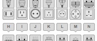
Application area
This standard applies to the group of products covered by the International Electrotechnical Commission (information technology, electrical and instrument making products) with a voltage of not more than 72.5 kV (hereinafter referred to as electrical equipment (equipment)). The standard states:
- a) a classification of the degrees of protection provided by enclosures against the penetration of solid objects (including protection of people from access to hazardous parts of products and protection of electrical equipment inside the enclosure from foreign solid objects) and against the penetration of water (protection of electrical equipment inside the enclosure from harmful effects resulting from the penetration of water );
- b) designations of the specified degrees of protection;
- c) requirements for each designation;
- d) methods and modes of control and testing for checking electrical equipment enclosures for compliance with the established degree of protection.
This standard is applicable only to enclosures that, in all other respects, comply with all the requirements of the standards for specific types of electrical equipment, and in terms of materials and technology ensure that the specified degrees of protection remain unchanged under normal operating conditions.
This standard is also applicable to empty enclosures, provided that the general test requirements and selected degree of protection for equipment of this type are met.
Requirements regarding the resistance of enclosures and electrical equipment in general to other external influencing factors, except external solid objects and water, as well as protection from contact with dangerous moving parts located outside the enclosure (for example, fans), are established according to other relevant standards (for example, GOST 15150, GOST 15543.1, GOST 17516.1, GOST 24682). Accordingly, the auxiliary letter W is not used (4.1, 4.2, section 8).
Barriers external to and external to the enclosure, and barriers provided only for personnel safety, are not considered part of the enclosure and are not the subject of this standard.
Note. Electrical equipment technical committees may establish the limits and uses of the classification in their standards, and may define the concept of “enclosure” in relation to their equipment. However, it is recommended that for such a specific classification the tests do not differ from those specified in this standard. Additional requirements may be included in the standard for specific types of equipment, if necessary. The instructions that should be reflected in the standards for specific types of products are given in Appendix B. Technical committees may, by type of electrical equipment, standardize other requirements for specific types of equipment, provided that the degree of safety is not worse than that established in this standard.
Use for electrical design
Protection requirements are of great importance when designing equipment, since the degree of protection must be assessed both for the outer shell and for its internal parts (partitions, curtains, etc.). Therefore, the degree of personal protection must also be determined for internal parts with which direct contact may occur during operation (for example, when rolling out a circuit breaker). In addition, even if the shell provides the required degree of protection, it is necessary that the internal partitions cannot be partially or completely removed. This does not apply to equipment such as motors, transformers, etc., but it is very important for certain cabinet compartments that must be accessible for equipment maintenance operations.
In this case, we mean two types of compartments:
- those that are rarely open (for example, tire compartments) and which are closed using a bolted connection. It is impossible to open such a compartment without using a special tool; this is not an easy operation. It is expected that adequate safety precautions will be taken.
- those that can be opened during normal operation of the equipment. They are typically closed by doors, which may be locked by an additional control system to supplement the protection provided by the enclosure.
During all maintenance and operation of the equipment, the continuity of the electrical circuit of the enclosure must not be disrupted, regardless of the position of the equipment.
Definitions.
The following terms with corresponding definitions are used in this standard:
3.1. Shell - a part that provides protection of equipment from certain external influences and protection in all directions from direct contacts (International Electrotechnical Dictionary (VEI) 826-03-12)2).
Note. For the purposes of this standard, this definition, taken from the International Electrotechnical Dictionary, requires the following explanation:
- 1) Enclosures require protection of people and animals from access to dangerous parts;
- 2) Guards, the shape of openings or any other means (whether related to the enclosure or formed by equipment within the enclosure) designed to prevent or restrict access to special test fixtures are considered part of the enclosure unless they are removed without the aid of a key or other tool. .
- 2) IEC 50(826):1982 International Electrotechnical Vocabulary (VEI). Section 826. Electrical Installations of Buildings.
3.2. Direct contact - contact of people or animals with live parts (International Electrotechnical Vocabulary (VEI) 826-03-05).
Note. This definition from the International Electrotechnical Dictionary is provided for informational purposes only. In this standard, the term “direct contact” is replaced by “access to hazardous parts”.
3.3. Degree of protection - the method of protection provided by the enclosure against access to hazardous parts, ingress of external solid objects and (or) water and verified by standard test methods.
3.4. The IP Code is a codification system used to indicate the degrees of protection provided by an enclosure against access to hazardous parts, ingress of external solid objects, water, and to provide additional information associated with such protection.
3.5. A dangerous part is a piece of equipment that is dangerous to approach or touch, and has signs of a hazardous production factor.
- 3.5.1. Live hazardous part is a live part which, under certain conditions, may cause electric shock (see IEC 536)1)
- 3.5.2. A hazardous mechanical part is a moving part other than a smooth rotating shaft that is dangerous to touch.
- 3.5.3. A hazardous production factor is an production factor, the impact of which on a worker under certain conditions leads to injury or other sudden sharp deterioration in health (GOST 12.0.002).
- 1) IEC 536:1976 (currently document 64 (CB) 196) Classification of electrical and electronic equipment according to the level of protection against electric shock.
3.6. The protection provided by the enclosure against access to hazardous parts protects people from:
- — contact with live dangerous parts under low voltage;
- — contact with dangerous mechanical parts;
- — proximity to dangerous live parts under high voltage at a distance less than the sufficient air gap inside the enclosure.
Note. Such protection can be provided:
- — the shell itself;
- - using barriers that are part of the shell, or due to distances inside the shell.
3.7. Distance sufficient to protect against access to hazardous parts - a distance that prevents the accessibility probe from touching or approaching hazardous parts.
3.8. Accessibility probe - a test probe for checking the sufficiency of distance from dangerous parts of equipment, simulating in an appropriate way a part of the human body or tool, or equivalent, held by a person.
3.9. Object Probe - A test probe used to test the ability to penetrate an enclosure, simulating an external solid object.
3.10. Hole - A gap or hole in an enclosure that exists or can be created by applying a test probe with a specified force.
IP69K standard
The German standard DIN 40050-9 has extended IEC 60529 to IP69K protection level. This degree of protection is used for washing at high liquid temperatures and under high pressure. The housings are designed not only to provide strong dust protection (IP6X), but also to withstand prolonged exposure to high-pressure water jets.
The IP69K degree of protection was originally developed for vehicles and road equipment, especially those that require regular intensive cleaning (dump trucks, concrete mixers, etc.), but today it is also used in other areas (chemical industry and food industry).
Go to catalog overview
Designations
The degree of protection provided by the enclosure is indicated by the IP code as follows:
4.1. IP code composition:
If there is no need to normalize the characteristic digit, it should be replaced with the letter X (or XX if two digits are omitted).
Additional and/or auxiliary letters are omitted without replacement.
When using more than one additional letter, alphabetical order is used.
If the enclosure provides different degrees of protection depending on the arrangement of equipment required by differences in installation, the corresponding degrees of protection shall be specified by the manufacturer in the instructions for each installation case.
The procedure for marking the shell is given in section 10.
4.2. IP code elements and their symbols
A brief description of the IP code elements is given in the diagram. A description of the degrees of protection is given in the sections indicated in the last column.
| Element | Numbers or letters | Implications for equipment protection | Implications for human protection |
| Code letters | IP | — | — |
| First characteristic digit | From penetration of external solid objects: | From access to dangerous parts: | |
| 0 | no protection | no protection | |
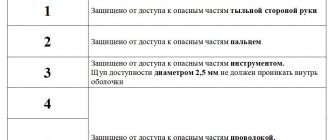
| 1 | diameter ≥ 50 mm | back of hand | |
| 2 | diameter ≥ 12.5 mm | finger | |
| 3 | diameter ≥ 2.5 mm | tool | |
| 4 | diameter ≥ 1.0 mm | wire | |
| 5 | dustproof | wire | |
| 6 | dustproof | wire | |
| Second characteristic digit | From harmful effects due to water penetration: | — | |
| 0 | no protection | ||
| 1 | vertical drop | ||
| 2 | drop (nominal angle 15°) | ||
| 3 | sprinkling | ||
| 4 | continuous spraying | ||
| 5 | jet action | ||
| 6 | strong jet action | ||
| 7 | temporary short dive | ||
| 8 | long dive | ||
| Additional letter (if necessary) | — | From access to dangerous parts: | |
| A | back of hand | ||
| B | finger | ||
| C | tool | ||
| D | wire | ||
| Auxiliary letter (if necessary) | Supporting information related to: | — | |
| H | high-voltage devices | ||
| M | driving condition during water protection tests | ||
| S | immobility during water protection tests | ||
| W1) |
- 1) See section “Introduction”, item a.
4.3. Examples of using letters in the IP code
The following examples explain the use and meaning of the IP code letters. Examples are discussed in more detail in Section 8.
- IPXX - no letters, no additions;
- IPX5 - the first characteristic digit is omitted;
- IPX2 - second characteristic digit omitted;
- IP20C - one additional letter used;
- IPXXC - both characteristic numbers are omitted, one additional letter is used;
- IPX1C - the first characteristic digit is omitted, one additional letter is used;
- IP3XD - the second characteristic digit is omitted, one additional letter is used;
- IP23S - one auxiliary letter is used;
- IP21CM - one additional and one auxiliary letter are used;
- IPX5/IPX7 - designation of two degrees of protection for one dual-use shell: protection against jets and protection against temporary (short-term) immersion.
Degrees of protection against water penetration, indicated by the second characteristic numeral
The second characteristic numeral indicates the degree of protection provided by the enclosures against harmful effects on the equipment due to the penetration of water.
Tests for the second characteristic figure are carried out using fresh water. The actual degree of protection may not be satisfactory when high pressure and/or solvents are used for cleaning operations.
Table 3 provides a brief description and definition of protection for each degree represented by the second characteristic digit.
Those listed in Table 3 should be normalized using only the second characteristic digit and not using a short description or definition.
Tests are standardized in section 14.
It is assumed that designation by the second characteristic digit up to 6 inclusive means compliance with all the requirements for smaller digits simultaneously. However, it is not necessary to carry out tests to establish compliance with any of the lower degrees of protection if it is obvious that the results of such tests will be obviously satisfactory.
It is assumed that enclosures designated by only one characteristic numeral 7 or 8 are not suitable for withstanding the effects of jets of water (identified by a second characteristic numeral 5 or 6) and shall not satisfy the requirements of digits 5 and 6, except in cases of double coding as follows:
| The shell successfully withstands impact tests | Designation and marking | Degree of use | |
| jets of water, second characteristic figure | temporary (short) or long-term immersion in water, second characteristic figure | ||
| 5 | 7 | IPX5/IPX7 | Double |
| 6 | 7 | IPX6/IPX7 | Double |
| 5 | 8 | IPX5/IPX8 | Double |
| 6 | 8 | IPX6/IPX8 | Double |
| — | 7 | IPX7 | Limited |
| — | 8 | IPX8 | Limited |
“Dual-use” enclosures must meet the requirements for exposure to jets and temporary (short) or prolonged immersion in water.
"Restricted Use" enclosures are considered suitable for temporary (short) or long-term immersion and are not suitable for exposure to jets of water.
Table 3. Degrees of protection against water, indicated by the second characteristic digit
| Second characteristic digit | Degree of protection | Test conditions, item number | |
| Short description | Definition | ||
| 0 | No protection | — | — |
| 1 | Protected from vertically falling drops of water | Vertically falling drops of water should not have any harmful effects | 14.2.1 |
| 2 | Protected from vertically falling water drops when the shell is tilted up to 15° | Vertically falling drops of water shall have no harmful effect when the shell is tilted from the vertical in any direction by an angle of up to 15° inclusive | 14.2.2 |
| 3 | Protected from water falling as rain | Water falling as splashes in any direction making an angle up to and including 60° with the vertical shall have no harmful effect | 14.2.3 |
| 4 | Protected from continuous splashing | Water splashing onto the enclosure from any direction shall have no harmful effect | 14.2.4 |
| 5 | Protected from water jets | Water directed onto the enclosure in the form of jets from any direction shall not have any harmful effects | 14.2.5 |
| 6 | Protected from strong water jets | Water directed onto the enclosure in strong jets from any direction shall not have any harmful effects | 14.2.6 |
| 7 | Protected from exposure to temporary (short) immersion in water | The penetration of water into the enclosure in quantities causing harmful effects must be prevented when it is immersed for a short time under standardized conditions of pressure and duration. | 14.2.7 |
| 8 | Protected from exposure to prolonged immersion in water | The penetration of water into the enclosure in quantities causing harmful effects must be prevented when it is immersed in water for a long time under conditions agreed between the manufacturer and the user, but more stringent than the conditions for figure 7 | 14.2.8 |
IP protection. Digital index.
| Protection class IP | IP x0 | IP x1 | IP x2 | IP x3 | IP x4 | IP x5 | IP x6 | IP x7 | IP x8 | IP x9 | |
| No protection | Protection from vertically falling drops of water | Protection against water drops falling at an angle of 15° from the vertical | Rain protection | Splash protection | Protection against pressurized water splashes | Protection against powerful water jets | Protection from water ingress during immersion to a certain depth and time | Protection against flooding (depth is indicated additionally, in m.) | Water for steam/high pressure cleaning | ||
| IP 0x | No protection | IP00 | |||||||||
| IP 1x | Particle protection > 50.0 mm | IP10 | IP11 | IP12 | |||||||
| IP 2x | Particle protection > 12.5 mm | IP20 | IP21 | IP22 | IP23 | ||||||
| IP 3x | Particle protection > 2.5 mm | IP30 | IP31 | IP32 | IP33 | IP34 | |||||
| IP 4x | Particle protection > 1.0 mm | IP40 | IP41 | IP42 | IP43 | IP44 | |||||
| IP 5x | Protection against dust | IP50 | IP54 | IP55 | |||||||
| IP 6x | Completely protected from dust | IP60 | IP65 | IP66 | IP67 | IP68 | IP69K |
An increase in one of the protection indicators correspondingly leads to an increase in the other (for example, a product that can be temporarily immersed in water is protected enough to completely keep out dust).
Therefore, only the above combinations of IP protection levels can exist. It is not possible to have a degree of protection such as IP28.
Degrees of protection against access to hazardous parts, indicated by an additional letter
The additional letter indicates the degree of protection of people from access to hazardous parts.
Additional letters should only be used:
- - if the actual protection against access to hazardous parts is higher than the protection indicated by the first characteristic digit;
- - or if only protection against access to hazardous parts is indicated, and the first characteristic digit is replaced by the symbol X.
For example, only a higher degree of protection can be provided by installing barriers, specially shaped openings or due to distances inside the shell.
Table 4 shows accessibility probes that conditionally reproduce individual parts of the human body or objects that are in a person’s possession. In addition, it defines the degrees of protection against access to hazardous parts, indicated by additional letters.
The degree of protection of an enclosure can be designated by an additional letter only if it satisfies all lower levels of protection. However, it is not necessary to carry out tests to establish compliance with any of the lower degrees of protection if it is obvious that the results of such tests will be obviously satisfactory.
Tests are standardized in section 15.
Examples of IP coding are given in Appendix A.
Table 4. Degrees of protection against access to hazardous parts, indicated by an additional letter
| Additional letter | Degree of protection | Test conditions, item number | |
| Short description | Definition | ||
| A | Protected from back of hand access | The accessibility probe - a sphere with a diameter of 50 mm - must remain at a sufficient distance from dangerous parts | 15.2 |
| B | Protected from finger access | A hinged test pin with a diameter of 12 mm and a length of 80 mm must remain at a sufficient distance from dangerous parts | 15.2 |
| C | Tool protected | The accessibility probe with a diameter of 2.5 mm and a length of 100 mm must be kept at a sufficient distance from dangerous parts | 15.2 |
| D | Protected from access by wire | The accessibility probe with a diameter of 1.0 mm and a length of 100 mm must be kept at a sufficient distance from dangerous parts | 15.2 |
Auxiliary letters
In the standard for specific types of products, additional information can be established using an auxiliary letter placed after the second characteristic digit or after an additional letter.
These exceptional cases must comply with the safety requirements of this standard, and the product specific standard must clearly set out additional procedures to be followed when testing to determine compliance with such classification.
The letters listed below have previously been used and have the following meanings:
| Letter | Meaning |
| H | High voltage devices |
| M | Tested for compliance with the degree of protection against harmful effects due to water penetration: equipment with moving parts (for example, the rotor of a rotating machine) in a state of motion |
| S | Tested for compliance with the degree of protection against harmful effects associated with the penetration of water: equipment with moving parts (for example, the rotor of a rotating machine) that are stationary |
| W | The letter is not used, see section “Introduction”, listing a |
Other letters may be used in product standards1).
The absence of the letters S and M means that the degree of protection does not depend on whether parts of the equipment are in motion or not. This, however, may necessitate testing under both conditions. However, one test under one of the specified conditions is sufficient if the feasibility of the protection requirements under other conditions is clear.
- 1) Before introducing a new letter, TC 341 should be consulted to avoid double use of additional letters.
IK code
For some countries, there is a need for security coding to protect the enclosure from mechanical shock. To address this need, they added a third characteristic digit to the IP code (countries such as Belgium, Spain, France and Portugal). But now that the IEC 529 standard has been adopted as a European standard, no countries can use an IP code different from that specified in this standard.
Since the IEC has refused to add a third digit to the IP code, the only way to add a third digit and still use the IP code is to create a different code.
This was done by the developers of the European standard EN 50102: IK code. The third digit of the IP code could have different meanings in different countries. This was contrary to the demands of committees associated with equipment manufacturers, which advocated a single coding system. Due to this, the powers of the IK code have been assigned values different from the old third digit of the IP code, see table of the correspondence between the old third digits of the French IP code and the IK code. Correspondence between the old third digits of the French IP code and the IK code
| Old third digits of the IP code standard NF C 20-010 (1986) | IP XX1 | IP XX3 | IP XX5 | IP XX7 | IP XX9 |
| IK code | IK 02 | IK 04 | IK 07 | IK 08 | IK 10 |
To eliminate coding confusion as much as possible, each degree of the IK code has been designated by a two-digit number.
Degrees of protection
The degrees of protection correspond to the impact energy values in Joules. Impact in this case refers to the mechanical impact of a special impactor (also called a test hammer) on the equipment under test and should be distinguished from vibration transmitted by a support and described in terms of vibration (that is, using characteristics such as frequency and acceleration).
The table shows the test means for the various IK code grades according to the current standard.
Test facilities for different grades of IK code
| IK code | IK 01 | IK 02 | IK 03 | IK 04 | IK 05 | IK 06 | IK 07 | IK 08 | IK 09 | IK 10 |
| Energy in Joules | 0,14 | 0,2 | 0,35 | 0,5 | 0,7 | 1 | 2 | 5 | 10 | 20 |
| Radius in mm (1) | 10 | 10 | 10 | 10 | 10 | 10 | 25 | 25 | 50 | 50 |
| Material (1) steel = S (2) polyamide = P (3) | P | P | P | P | P | P | S | S | S | S |
| Pendulum striker | Yes | Yes | Yes | Yes | Yes | Yes | Yes | Yes | Yes | Yes |
| Spring striker | Yes | Yes | Yes | Yes | Yes | Yes | Yes | No | No | No |
| Vertical striker | No | No | No | No | No | No | Yes | Yes | Yes | Yes |
(1) impact element
(2) Fe 490-2 according to ISO 1052, hardness from 50 HR to 58 HR according to ISO 6508
(3) hardness HR 100 according to ISO 2039/2
In practice, degrees of protection against mechanical shock can be established by using different types of impactors: pendulum impactor, spring impactor or vertical impactor (see Fig. 7).
Rice. 7: Spring striker (a) (according to IEC 68-2-63) and pendulum striker (b) (according to IEC68-2-62). It should be noted that a calibration device is also required, not shown here
Each type of impactor has specific capabilities, providing different energies and directions of impact. To create a given energy pulse, various combinations of the parameters of the test tools used with the dimensions and properties of the impact element are used.
The product standard must specify which parts of the product are to be impacted and the permissible level of impact.
Examples of designation using IP code
9.1. IP code without additional letters:
Shell with the specified designation (IP code):
- (3) - protects people holding tools with a diameter equal to or greater than 2.5 mm from access to dangerous parts;
- — protects the equipment inside the enclosure from penetration of external solid objects with a diameter equal to or greater than 2.5 mm;
- (4) - protects the equipment inside the enclosure from harmful effects due to splashing of the enclosure with water from all sides.
9.2. IP code using additional letters:
Shell with the specified designation (IP code):
- (2) - protects people from accessing dangerous parts with their fingers;
- — protects the equipment inside the enclosure from the ingress of external solid objects with a diameter equal to or greater than 12.5 mm;
- (3) - protects the equipment inside the enclosure from the harmful effects of water in the form of rain;
- (C) - protects people from accessing dangerous parts if they are holding a tool with a diameter equal to or greater than 2.5 mm and a length not exceeding 100 mm (the tool can penetrate the entire length of the enclosure);
- (S) - Tested to provide protection against harmful effects due to ingress of water when all parts of the equipment are stationary.
Protection class IP 68.
The most common degrees of protection are IP20, IP44, IP54, IP65.
- IP20 - Electrical equipment with a degree of protection of IP20 is usually used indoors.
- IP44 - Used in a room with high humidity, for example, in a bath, it is worth installing devices with a degree of protection IP44.
- IP54 - Common degree of protection for electrical components.
- IP55 - Most often, manufacturers of electrical cabinets and panels indicate the degree of protection IP55.
- IP65, IP67, IP68 - Requirements for equipment exposed to weather conditions. Equipment with a degree of protection IP68 can be immersed in water; the depth of immersion is indicated additionally.