Relay protection devices
Currently, the term “relay” refers to a wide group of automatic instruments and devices used in relay protection, automation, telemechanics, telephony and other branches of technology. At the end of the 19th century, the first fuses appeared, which were then replaced by electromechanical and static (analog) relay protection. In our country, since the early 1990s, such devices have been gradually replaced by digital ones. At the moment, most of the relay protection devices in Russia still belong to technology of previous generations, but at new facilities or after reconstruction in the vast majority of cases only digital relay protection is installed.
High-quality digital relay protection devices are produced by both domestic manufacturers and foreign companies. Several Russian-made devices can be noted:
- microprocessor relay protection unit “BMRZ” (“Mekhanotronika”, St. Petersburg);
- "SHE" (Ekra, Cheboksary);
- "Sirius" ("Radius" Zelenograd).
Foreign-made relay protection devices:
- "Silirotec" ("Siemens");
- "Seliam" (Schneider Electric);
- "SliAC", "REF" ("ABB").
Proper adjustment of relay protection also requires appropriate equipment, such as domestic RETOM-11, RETOM-21, RETOM-51, RETOM-61, or foreign analogues. It is important that the installation of relay protection is carried out only by qualified specialists who have experience and are able to perform this serious task efficiently and on time.
Electrical laboratory services "EnergoServiceGarant"
Our company provides mobile electrical measuring laboratory services at a low price. We offer you favorable terms of cooperation:
- Tests and diagnostics in accordance with established requirements and standards.
- Qualified personnel (with clearance).
- Urgent and scheduled site visits.
- High-precision equipment (megohmmeters, microohmmeters).
- Documentary support (we provide a full list of technical documentation, including technical reports, research and defect reports, recommendations for troubleshooting).
To order, contact the company manager by phone listed in “contacts” or fill out the feedback form. We will contact you shortly. Visit our website to find out the preliminary cost of services (price list).
Causes and consequences of relay protection and automation faults
Standardized values and frequency of checks, requirements for relay protection, basic methods for setting up relay protection, calculation examples are listed and described in regulatory documents: RD “Instructions for testing relay protection devices”, PTEEP , PUE 7th ed. Chapter 1.8., methodological manuals, reference books on relay protection devices. They determine that before an electrical installation is allowed to operate, it is necessary to carry out commissioning work, and for equipment up to 1000V, acceptance tests are required. Short circuits, insulation damage and overloads occur due to a number of reasons, some of which cannot be predicted - these are the actions of personnel, breakdown or peeling of insulation, wire breakage due to natural phenomena or anthropogenic influences, turning on of grounded equipment under voltage, and so on. In order to minimize the consequences of such situations, it is necessary to adjust the relay protection after installation and check the relay protection in operation.
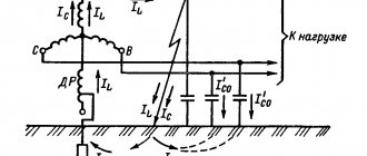
In order to understand the principle of setting up relay protection, you need to know what happens during a short circuit. Typically, large currents of tens of thousands of amperes are applied to the fault location within a very short time. They cause not only breakdown, but also severe heating and overheating of live parts. In this case, the insulation may catch fire and the electrical installation may catch fire. Setting up relay protection allows you to automatically turn off part of the power system in order to de-energize a part of an electrical installation or a section of the network damaged as a result of an emergency. Correctly configured relay protection by timely operation reduces the consequences of an accident, as well as voltage drop in the rest of the network, stopping of electric motors and generators connected in parallel, and damage to process equipment.
0.4 kV circuit breakers also belong to relay protection; during acceptance tests, their characteristics for overload (with a time delay) and cutoff (instantaneously or with a minimum time delay) are checked. Triggering of protection devices up to 0.4 kV allows you to quickly disconnect the damaged section of the network and prevent an accident without the participation of personnel: at the moment the current supply is stopped, the electric arc goes out and the rest of the power network operates normally. This, in turn, prevents malfunctions of the main equipment, its damage and production stoppages. With proper adjustment of relay protection, enterprise losses are minimized.
Short circuits are the most common problems in power systems because they have many different causes. Also, when setting up relay protection, it is necessary to take into account that the following situations are possible:
- phase ground fault in a network with an isolated neutral;
- overload;
- lowering the oil level in the transformer expander;
- the release of gas as a result of the decomposition of oil in the transformer, and so on.
According to the requirements of PTEEP: “ power equipment of power plants , substations and electrical networks must be protected from short circuits and violations of normal operating modes by automation devices and electrical automation . Relay protection devices must be constantly turned on, except for devices that must be taken out of operation in accordance with the purpose and principle of operation, the operating mode of the power system and selectivity conditions. Emergency and warning devices must always be ready for action.” Thus, we can conclude that the second purpose of the relay protection system is to detect violations of the operating mode of electrical equipment and signal this to personnel located at a distance - in cases where personnel are present, shutdown using established relay protection is also carried out, but with a time delay, which makes it possible to use the human factor.
Configuring PAS and PDS
Despite the fact that in this article this section follows the server configuration section, the configuration of the PAS and PDS was performed at the previous stage, since the configurations of these devices are presented in the SCD file. There are no differences in the configuration of the ISAS and SDS compared to any other system implemented in accordance with the IEC 61850 standard. Communications between the ISAS system and the SAS/SDS were implemented exclusively using the GOOSE and Sampled Values communication services. The MMS protocol was not used at the process level.
Adjustment of relay protection and automation devices
Regulatory documents establish that “the adjustment of relay protection and automation devices is carried out by trained employees from among electrical personnel who have qualifications and experience. The work is carried out according to methods approved by the head of the enterprise. Testing equipment and measuring instruments used to carry out work must have test certificates and verification certificates.”
At a large enterprise, in the service of the chief power engineer, there are sections or groups of relay protection, automation and telemetering. If the enterprise does not have such a service, a specialized organization that has a licensed electrical laboratory on staff is engaged in setting up relay protection. Operating personnel must check the relay protection and automation according to the schedule, by visual inspection and reading information from the relay protection units. If signals about malfunctions, accidents or errors are received regularly, then checks and adjustments of relay protection should be carried out regularly; in the absence of such a possibility, third-party operational mobile teams of electrical laboratories are called.
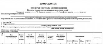
The inspection results are recorded in the relay protection log and relay protection cards. They must reflect all work performed during the period that has passed since the last inspection, changes in settings, circuits, relay protection devices, newly introduced or taken out of service. Entries are also made in the operational log. All changes in the electrical circuit diagrams of the secondary switching cells are recorded. The absence of as-built documentation for relay protection devices and setting maps in the chief power engineer's service is a serious violation of the requirements of legislation and regulatory documents in the field of energy and entails punishment or large fines. During operation at the consumer's site, the personnel configures the relay protection in accordance with PTEEP: “the serviceability of emergency and warning alarms, switch position alarms, the presence of voltage on the operating current buses, all sources of direct and alternating current and the operating mode of recharging devices are checked.” Setting up relay protection also includes checking the insulation resistance of operating current circuits, the presence of operating current, the serviceability of fuses, the serviceability of ATS sources, the serviceability of switch control circuits, alarm circuits, and control of switching devices. It is also important to check “the correct position of circuit breakers, switches and other switching devices in the ATS circuit and the compliance of their positions with the primary circuit. Using the installed measuring instruments, they monitor the serviceability of the circuits of voltage transformers and fuses.”
Regulatory documents also provide a list of relay protection and automation faults that personnel can correct on their own. This:
- Turning on circuit breakers or replacing fuse links in VT circuits or power supply to relay protection devices.
- Disabling all relay protection and automation devices in the event of a break in the shutdown circuits of a switch or other switching device, followed by the dispatcher carrying out the measures provided for the connection, completely disconnected from the relay protection;
- Determination of the location of damage when a ground fault appears in the operational current circuits;
- Disabling devices that automatically close the circuit breaker in case of damage to the rectifiers supplying the circuits for turning on the electromagnetic drives.
Regulations
Regulatory documents, in accordance with the requirements of which relay protection is configured:
- PUE 7th edition section 1, ch. 1.8 “Acceptance testing standards”
- RD 34.45-51.300-97 “Scope and standards for testing electrical equipment”
- Design documentation for equipment and relay protection units.
- PTEEP
- RD 34.35.302-90. “Standard instructions for organizing and performing work in relay protection devices and electrical automation of power plants and substations.”
- RD 153-34.0-35.617-2001 “Rules for the maintenance of relay protection devices, electrical automation, remote control and signaling of power plants and substations 110-750 kV”
- E.S. Musaelyan “Handbook for setting up EO ES and PS. Secondary circuit equipment"
- Chernobrovov N.V. "Relay protection"
- Kakuevitsky L.I. Krutitsky A.Yu. "Directory. Protection and automation relays"
- Methods for checking relay protection and automation devices
Using a relay
In power supply systems, short circuits, local overloads, and damage to the insulating layer on cable lines may occur. The incident occurs in a separate area. To protect a “healthy” network, immediate shutdown of the dangerous circuit is required. It is impossible to complete the task manually given the complexity and size of the network. Setting up relay protection and automation allows you to set up instant shutdown of a section and secure switchgear.
The possibility of an accident spreading cannot be completely eliminated. Simultaneous damage to several circuits or too strong a breakdown lead to failure of 75–90% of devices. Correct adjustment of automatic equipment performed by LABSIZ reduces the risk of a total accident to a minimum.
The laboratory works with relays:
- analog;
- digital type.
The former are found in old enterprises, the latter are installed when installing new circuits, lines, and power supply systems. "LABSIZ" carries out regular, extraordinary maintenance of relay protection and automation, and post-emergency adjustment.