According to current technical standards (PUE, in particular), during the operation of any electrical equipment, increased attention is paid to protecting working personnel and private consumers from electric shock. Research into this problem typically involves technical issues such as:
- what is called protective grounding in general?;
- the ability to connect to circuit elements and select the type of grounding device (GD);
- What is preferable: protective grounding or so-called “grounding”?
Another important point is the user’s desire to become familiar with how the operating parameters of the ground electrode can be calculated and how this design works. Each of these issues regarding protective grounding devices requires separate and careful consideration.
Classification of grounding systems (natural and artificial structures)
Both natural and artificial systems and devices are widely used as grounding devices with characteristics that meet the requirements of the PUE. Natural storage facilities are metal structures and pipelines already buried in the ground or parts thereof that are in direct contact with the ground.
Additional information: These also include unbroken cable sheaths, metal tongues and similar elements of grounded structures and communication systems.
Natural grounding conductors of buildings and structures
Since there are absolutely no special costs required for the arrangement of such earthing devices, they are recommended for use in the first place by current standards. And only if natural grounding structures cannot be found, it is necessary to arrange their artificial analogue. To find out what is the definition of artificial grounding, you will need to understand it in more detail.
Such a system is understood as a device manufactured specifically for the purpose of organizing local grounding at a transformer substation or on the consumer side. Driven vertical or laid horizontal steel blanks are traditionally used as structural elements. In the first case, steel rods with a diameter of at least 12 mm and a length of 3-5 meters are used, and in the second, angles with a standard size of 50x50x6 mm are used. For the same purpose, metal pipes with a diameter of at least 6 mm can be selected.
Installation of a ground electrode in the ground
Vertical electrodes (see photo on the left) are driven into the ground to a depth of 2.5 meters, for which a trench about 0.5-0.6 meters deep is first prepared in it. The head of the driven electrode should protrude above the ground surface of the dug trench to a height of about 0.1-0.2 meters. Vertical structural elements are connected to horizontal jumpers for welding.
Please note: The trench system with the electrode rods placed in them must be covered with previously selected soil, cleared of large stones and foreign debris.
The choice of parameters of electrode rods and the depth of their immersion depend on the nature of the soil in a given area and the characteristics of its climatic conditions.
According to GOST and the current provisions of the PUE, the resistance Rz of the ground loop during the period of operation should be:
- no more than 8 Ohms with a substation supply phase voltage of 220/127 Volts,
- about 4 Ohms with a linear supply voltage of 380 Volts;
- no more than 2 Ohms with a power supply of 660/380 Volts.
These parameters are valid for the case when chargers are used in networks with voltages up to 1000 Volts. If they are installed for existing electrical installations with operating voltages above 1000 Volts and with low ground fault currents, the resistance is calculated using special formulas (see PUE).
Circuit design
Components
The previously mentioned grounding resistance (Rз) of the circuit is the main parameter controlled at all stages of its operation and determines the effectiveness of its use. This value must be so small as to provide a free path for the emergency current tending to flow into the ground.
Note! The most important factor that has a decisive influence on the value of grounding resistance is the quality and condition of the soil at the site of the installation. Based on this, the charger in question or the ground loop of the charge circuit (which in our case is the same thing) must have a design that meets the following requirements:
Based on this, the charger in question or the ground loop of the charge circuit (which in our case is the same thing) must have a design that meets the following requirements:
- It must include a set of metal rods or pins with a length of at least 2 meters and a diameter of 10 to 25 millimeters;
- They are connected to each other (necessarily for welding) by plates of the same metal into a structure of a certain shape, forming a so-called “grounding conductor”;
- In addition, the device includes a supply copper busbar (also called electrical) with a cross-section determined by the type of equipment being protected and the magnitude of the drain current (see the table in the figure below).
Tire Section Table
These component devices are necessary to connect the elements of the protected equipment with the descent (copper busbar).
Differences in device location
According to the provisions of the PUE, the protective circuit can have both external and internal design, and each of them is subject to special requirements. The latter establishes not only the permissible resistance of the ground loop, but also stipulates the conditions for measuring this parameter in each particular case (outside and inside the object).
When dividing grounding systems according to their location, it should be remembered that only for external structures the question of how the grounding resistance is normalized is correct, since it is usually absent indoors. Internal structures are characterized by wiring of electrical busbars along the entire perimeter of the premises, to which grounded parts of equipment and devices are connected through flexible copper conductors.
For structural elements grounded outside the facility, the concept of re-grounding resistance is introduced, which appeared as a result of the special organization of protection at the substation. The fact is that when forming a neutral protective conductor or a working conductor combined with it at the supply station, the neutral point of the equipment (step-down transformer, in particular) is already grounded once.
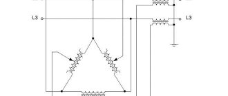
Therefore, when another local grounding is made at the opposite end of the same wire (usually a PEN or PE bus connected directly to the consumer panel), it can rightfully be called repeated. The organization of this type of protection is shown in the figure below.
Re-grounding
Important! The presence of local or repeated grounding allows you to insure yourself in case of damage to the protective neutral wire PEN (PE - in the TN-CS power supply system). Such a malfunction is usually found in technical literature under the name “zero burnout”
Such a malfunction is usually found in technical literature under the name “zero burnout.”
Protective grounding and grounding
To understand what protective grounding , you will need to understand the features of the organization and arrangement. At the same time, it is important to learn to distinguish it from its working analogue, which is necessary for the normal functioning of the supply circuits. Protective grounding, in contrast to worker grounding, provides safe conditions for handling equipment, the open parts of which are energized in the event of an accident. However, there are often situations when it is not possible to equip a protective circuit at a specific facility. This may be due to the lack of conditions for its placement or other organizational reasons.
Important! To protect a person from electric shock in conditions where it is impossible to organize conventional grounding, protective grounding is used.
To understand in detail what this protective grounding is, you will need to familiarize yourself with the principle of its operation. The essence of this system is to connect exposed conductive parts that may be energized with a tightly grounded neutral of the supply line (transformer).
Protective grounding and grounding solve the same problem of ensuring human safety
Thus, protective grounding and grounding for electrical installations, as systems, solve the same problem of ensuring human safety, but each in its own way (see photo above). In the first case, to organize a chain of emergency current flow, a local grounding device is used, which reduces the high potential on the equipment body to a safe level. When arranging a grounding system, the neutral of the supply network is used, which makes it possible to turn an emergency situation into a regular single-phase short circuit. The scope of application of protective grounding is all cases where it is impossible to use a conventional grounding system.
Let's analyze the situation with diagrams
From the point of view of the flow of electric current, there is no difference between grounding and grounding. The neutral wire in any case has electrical contact with physical ground.
Accordingly, when a phase is shorted to the housing, the same short circuit will occur and the circuit breaker will turn off. Of course, (subject to proper connection: the socket must have a third ground contact, just like an electrical appliance. For this reason, electricians, violating the requirements of the Electrical Installation Rules, often separate the ground bus from the zero contact of the input panel.
Let's imagine a situation where the neutral wire is broken for some reason:
- loss of contact due to corrosion (in old high-rise buildings this is a working situation);
- mechanical rupture of the cable due to repair work with violations of technology (unfortunately, also not uncommon);
- unauthorized intervention by a home-grown “electrician”;
- accident at the substation (only the zero bus may be disconnected).
In the diagram it looks like this:
When organizing protective grounding, the electrical circuit between the physical “ground” and the grounding contact of the electrical appliance is broken. The installation becomes defenseless. In addition, a free phase without a load can create a potential equal to the input voltage at the nearest substation. Typically this is 600 volts. You can imagine the damage that will be caused to the electrical equipment that is turned on at this moment. In this case, there is no current leakage to the physical ground, and the circuit breaker will not trip.
Imagine that at this moment you simultaneously touch a phase (a breakdown on the body of an electrical installation) and a metal object that has a physical connection with the ground (a water tap or a heating radiator). You can get electrocuted at 600 volts.
Now let's see what the difference is between grounding and neutralizing (in our diagram). If the zero bus breaks, the power to all electrical installations in this circuit will simply disappear. There will be no electric shock under any circumstances: the electrical circuit between the physical ground and the grounding contact of electrical appliances is not broken. We have already preserved our health. Now let's see what happens to electrical installations. The maximum damage is a burnt-out incandescent lamp closest to the input panel. Moreover, trouble will only occur if the voltage on the phase wire increases. The current strength will increase (according to Ohm's law), the circuit breaker will work, and perhaps other electrical appliances will not be affected.
It is for this reason that the PUE strictly prescribes: protective grounding and grounding of electrical installations must be organized independently of each other, using different lines.
For reference: Wire color coding is usually used:
- The phase is brown or white.
- The working zero is blue.
- Protective grounding is a yellow-green shell.
If you have a modern home, then grounding and grounding are carried out in accordance with the Electrical Installation Rules. This can be easily checked by looking at the input cable in the panel. In addition, you can check the correct connection yourself.
Purpose and principle of operation of protective grounding
It has already been noted that the electrical grounding system is designed to protect personnel servicing electrical installations and ordinary users from high voltage. Dangerous potential most often reaches metal parts of equipment or household appliances completely accidentally (due to damage to insulation, for example). The purpose and principle of operation of the charger is easier to understand if we remember that reliable contact with the ground leads to the spread of dangerous current and a decrease in the potential level.
Thus, the purpose of the protective device is to create conditions that reduce the risk of injury to living organisms by a dangerous current by reducing the voltage at the point of closure.
The principle of operation of the grounding system is to reduce the high potential that accidentally appears on the equipment body to a value that is safe for the human body. In the absence of functional grounding, unintentional contact with it is tantamount to direct contact with the phase conductor. Taking into account the fact that the operator most often stands on a reinforced concrete floor, and his shoes are not always dry, a significant current can flow through his body.
The presence of protective grounding creates conditions for the main part of the current from the system to flow into the ground
The presence of functional grounding creates the conditions for the main part of the current from the system to flow into the ground. Its share in the human body will be negligible and will not cause him any harm (see photo on the left). This guarantees the required level of electrical safety when working with a grounded device.
Additional information: Grounding systems, along with the technical grounding already known to us, are not the only options for ensuring safety during the operation of electrical installations.
Along with them, the PUE recommends for use special emergency power line shutdown devices (RCDs), which are triggered when leaks to the ground occur.
Grounding
Now the main question is, what is the difference between grounding and grounding? It's all about installing additional protective devices. To achieve safe operation of household electrical appliances, it is necessary to install either an RCD (residual current device) or differentiated circuit breakers into the distribution board. Both types of devices have in their design a special working element that equalizes the current strength in the phase and neutral wires.
Ground connection diagram
- If the network and household appliances operate in normal mode, then the currents in different circuits are the same in magnitude, but flow in different directions: in phase into the apartment, in zero out of it. That is, the entire system is balanced, so household appliances work well according to their nominal parameters.
- If there is an insulation break anywhere in the electrical system (wires, household appliances, machines, etc.), the current begins to flow to the ground. In this case, this current passes past the zero conductor. That is, grounding ceases to work. An imbalance occurs in the working body of an RCD or a differentiated machine. As soon as the violation begins, a protective device is immediately activated, which disconnects the contacts. Electricity is no longer supplied to the system.
And one more point that concerns protective grounding and grounding. Experts recommend installing a separate circuit in which the so-called PE conductor is mounted. It is specially taken outside the distribution board and installed near the socket in the socket. In this case, the socket must be three-phase: phase, neutral and ground. The conductor is connected to ground.
Please note that when plugged into a socket, the plug from a household appliance first touches the ground, and then the two main phases. The same thing happens at the moment of switching off: first the phases are output, then lastly the ground
This is a guarantee that in the event of a short circuit in the household electrical appliance itself, the entire system will not fail due to the increased current in it.
Typically, the RCD is installed in the distribution panel after the main input circuit breaker. It is necessary to take into account the fact that the residual current device does not protect the electrical network from wire short circuits. The likelihood that this device itself will fail for this reason is very high.
Therefore, it is so important to adjust the parameters of the introductory machine with the parameters of the RCD itself. The best option is to install another machine in front of the device, which will be identical in parameters to the protection
By the way, it should be noted that the RCD with a machine for it is, in fact, an ordinary differential machine. The latter costs more than a protective device, but is much more compact in size.
Now you can understand the differences between grounding and grounding.
How to calculate a system of grounding elements
Getting acquainted with the procedure for calculating grounding should begin with finding out what value to take as the defining indicator and for what purpose the procedure itself is used. This parameter is the resistance of the protective circuit, which depends on such technical indicators as:
- Dimensions and shape of the grounding system.
- The depth of its immersion into the ground.
- Condition of the soil in the area.
Important: A large “contribution” to the formation of the conductivity of the current flow chain is made by the contact resistance of the contacts in the design of the charger itself.
It is known that an artificial grounding loop consists of a set of vertical and horizontal metal elements and a copper busbar connecting them. In order to ensure minimal resistance to current flow into the ground, it is necessary:
- use grounding systems with a large area of contact with the ground (if necessary, increase the number of vertical pins and their pitch);
- constantly monitor the condition of the soil at the location of the device and be able to determine the soil resistivity;
- control the reliability of welded joints.
To assess the real performance indicators of the charger, it is necessary to familiarize yourself with the existing methods for measuring the conductivity of the grounding system.
Grounding tasks
The artificially created contact between the electrical installation and the ground is called grounding. Its task is to reduce the voltage on the device body to a level that is safe for living beings. In this case, most of the current is diverted into the ground. For the grounding system to work effectively, its resistance must be significantly lower than that of the rest of the circuit. This requirement is based on the property of electric current to always choose the least resistance along its path.
Note! Grounding is used exclusively in electrical networks with an isolated neutral.
The fault current is sometimes insufficient when using a ground electrode with a relatively high resistance for the response of protective devices. Therefore, another task of the grounding system is the increase in emergency fault current.
Types of grounding devices:
- Lightning protection. Pulse currents entering the system as a result of lightning strikes are removed. Used in lightning rods and arresters.
- Workers. Designed to maintain normal operation of electrical installations. Used in both normal and emergency situations.
- Protective. They protect people and animals from electric shock passing through metal objects in the event of breakdown of phase conductors.
Grounding devices can be natural or artificial:
- Natural products include metal products whose main function is not to drain current into the ground. Such grounding conductors include pipelines, reinforced concrete elements of buildings, casing lines, etc.
- Artificial ground electrodes are systems created specifically for current drainage. These are steel strips, pipes, corners and other metal elements.
For the grounding system, you cannot use pipes intended for transporting flammable substances (both gases and liquids), aluminum parts, and cable sheaths. Objects coated with an anti-corrosion insulating layer are also not suitable for this purpose. It is prohibited to use water supply and heating pipes as grounding conductors.
Typical calculation methods
To calculate protective grounding, you will need to determine in advance the following initial indicators:
- Dimensions and total number of steel pins driven into the ground.
- The distance left between them (installation pitch).
- Depth of rods.
- The resistivity of the soil itself at the site where the storage facility is installed.
In addition to them, it is important to take into account the geometric shape and material of the workpieces from which the system of grounding conductors is welded (either it is a standard steel angle, or a copper strip, etc.).
According to the current regulatory documentation (PUE, in particular), the minimum dimensions of the selected workpieces must be no less than:
- steel strip with a cross-section of at least 100 mm2;
- steel corner with sides 4x4 mm;
- round steel bar with a cross section of 16 mm2;
- metal pipe with a diameter of 32 mm and a wall thickness of at least 3.5 mm.
The minimum dimensions of the pins or reinforcing bars used to manufacture the charger system are selected from the following considerations. The length of the workpieces cannot be less than 1.5-2 meters. The distance between them is taken as a multiple of the length of each rod. Depending on which site is chosen for arranging the memory, they are installed either in a row one after the other, or in the form of a square or a regular triangle. According to the calculation method used, its main task is to determine the number of rods and the parameters of the connecting strip (its length and thickness).
To calculate all parameters of protective grounding, you can use the online calculator on our website.
Example of calculation of memory elements
As an example, let us consider the calculation of the resistance to emergency current drainage for a vertical rod taken in a single copy (drawing on the right).
Drawing of a vertical ground electrode
To carry it out you will need to know the following initial data:
ρ is the resistivity of the soil at this location (in Ohms per meter);
L – length of the rod in meters;
d – its main standard size (diameter) in meters;
T – distance to the middle of the rod from the surface in meters.
If we take into account the value limiting the flow of current for horizontal charger elements, then the resistance for their vertical analogues is calculated using the following formula:
Formula for calculating current spreading resistance for vertical grounding conductors
In a situation where the grounding device is installed in heterogeneous soil (experts call it two-layer), the resistivity is calculated as follows:
Formula for calculating resistivity for heterogeneous soil
where – Ψ represents the seasonal coefficient;
ρ1 and ρ2 – resistivity of various layers of local soil (upper level and lower layer, respectively), measured in Ohms per meter;
H – thickness of the layer located in the upper part of the soil in meters;
t – total depth of vertical elements (depth of the entire trench), equal to approximately 0.7 meters.
The required number of rods (excluding horizontal components) is determined as follows:
where Rн represents the spreading resistance normalized according to PTEEP.
If we take into account the horizontal components of the charger, the formula for the number of vertical pins will take the following form:
where η in is the system utilization coefficient, indicating how strongly the spreading currents from individual elements influence each other (at their different locations).
Additional information: When a system of rods is placed in parallel, the mutual influence of the spreading currents of individual pins is much stronger.
That is why, if they are located too close, the total resistance of the protective circuit increases significantly. The number of grounding elements obtained after using the above formulas is usually rounded up to a larger value. It is possible to automate the calculation of grounding based on them if you use the “Electrician v.6.6” program specially developed for this purpose. You can download this software for free on the corresponding website on the Internet.
Difference in comparison
You don't have to be an electrician to understand the differences between these devices. It is enough to understand the essence of their purpose. If one diverts dangerous voltage into the ground, then the other equalizes it to safe levels.
Proper connection of electrical equipment and electrical appliances prevents electric shock. In an extreme situation, a short circuit occurs on the housing. The protection is triggered and disconnects the electrical circuit. In this case, grounding works. The earth is used as a conductor.
There was voltage in the house, on the heating device. A dangerous situation must be prevented by grounding. But the pipes between the apartment and the basement were changed: plastic ones were installed instead of steel ones. They disconnected the conductor. Grounding didn't work. The SUP eliminated the electrical potential difference using conductors. The danger has been eliminated.
Comparing these devices helps to understand the differences between them:
- SUP is the electrical connection of metal structures with each other and the ground. They have equal potential.
- Grounding - connection of all metal parts with a ground electrode.
- The potential equation concerns only structures that may be energized among themselves.
- Grounding concerns only the drainage of currents into the ground.
- The purpose of the control system is to equalize the potentials of the conductive parts among themselves: to make them safe for the lives of people and animals.
- The purpose of grounding is to equalize the potentials of grounded parts of equipment with the ground potential.
They can be called comprehensive protection against electric charge. But before installing a potential equalization system in your house, call an electrician, read the PUE, look at the house construction project. What grounding system is it built with?
For example, with TN-C and a combined PEN conductor, DSUP is prohibited. Reconstruction with transition to the TN-CS system is required.
The difference between a working ground wire and a protective bus
The working and protective grounding conductors differ from one another, first of all, in their purpose. The first of them serves the purpose of providing the load with phase current, creating a circuit for its flow from the transformer to the consumer. The second one is used purposefully for arranging grounding systems (both on the station side and at the consumer).
Please note: In production or in private homes, for example, the grounding conductor is used to organize the so-called “local” or repeated grounding.
Thus, the main functional purpose of the operating bus is to create conditions for the uninterrupted operation of station and local electrical equipment by laying a line separate from the protective conductor. The grounding system functionally solves completely different problems - it creates conditions for the safe operation of this equipment. In addition, lightning rods installed in enterprises or private homes are connected to it. It is also used when it is necessary to create grounding systems and potential equalization in electrical installations.
Schematic diagram of dividing a PEN conductor into PE and N
In order not to confuse these two types of grounding conductors on electrical diagrams, letter and color designations have been specially introduced to indicate the method of their installation (combined or separate). In the first case, the common wire is designated as PEN , and when laid separately, they are functionally divided into PE and N , neutral or working (photo on the left). Depending on the design method of these two conductors, there are several types of grounding systems that are acceptable for use in Russian power supply networks.
Grounding
Let's start by analyzing each system separately.
Thus, grounding is a deliberate connection of an electrical network, device or equipment with a special structure buried in the ground through a neutral conductor.
Essentially, this is a single system that connects the conductive elements of devices and equipment (for example, their housings), the wires connected to them, and the pins buried in the ground (circuit).
Due to the high resistance of the circuit, when the phase wire touches the housing in the event of a breakdown, most of the voltage goes into the ground, and although the potential will still remain on the housing, its value will be significantly reduced and not dangerous to humans.
The international standard developed by the IEC includes several grounding systems, the differences between which boil down to different types of grounding of the power source (generator or transformer substation), and grounding of open sections of the network and devices.
The standard includes three systems - TN, TT and IT.
The first letter of the index indicates the type of grounding of the source (T - “ground”), it turns out that in the first two systems the transformer substation is connected to the grounding loop.
As for the third (IT), its power source is insulated or connected to a device that provides high resistance (I - insulation).
The second letter of the index indicates the type of grounding of open sections of the network. In the TN system (N - neutral), these sections are connected to the neutral conductor of the source connected to the ground loop (solid grounding of the neutral).
To connect equipment and devices, working (N) and protective (PE) neutral conductors are used.
As for the other two systems - TT and IT, the second letter index indicates that open sections of the network, equipment and devices are grounded by their own separate circuit.
In turn, the TN system is divided into subsystems, there are three of them - TN-C, TN-S, TN-CS.
The differences between them come down to the use of different protective conductors with which consumers are connected to the source neutral.
The TN-C subsystem uses a combined conductor (PEN), which combines both the working and protective “zero”. This subsystem is already outdated, so it is not used when laying new electrical networks.
The TN-S subsystem differs in that it has working and protective “zeros” - these are different conductors. That is, an N-conductor is connected to the neutral, and a PE-conductor is connected to the grounding loop, even though they are combined at the power source.
The third subsystem – TN-CS is an intermediate link between the first two subsystems. It has a PEN conductor extending from the neutral, that is, the neutral conductors are combined, but in a certain section of the network they are separated and the working and protective “zeros” are approached separately to consumers. After separation, the protective “zero” is additionally grounded.
You can read more about grounding systems, their advantages and disadvantages here https://elektrikexpert.ru/sistemy-zazemlenij.html.
The requirements placed on grounding are quite serious. After all, it must ensure the removal of dangerous voltage from the device or equipment in the event of a breakdown.
Grounding is mandatory for networks in which the voltage is higher than 42 V AC or 110 V DC.
Therefore, during design, parts of the network and equipment that are subject to mandatory grounding must be correctly selected, and control must be exercised to ensure that the grounding circuit is not interrupted anywhere.
They also take the choice of conductors seriously; their cross-section must provide the appropriate throughput.
All requirements that are put forward to grounding systems are specified in the PUE (Electrical Installation Rules).
Here you can learn more about how to make grounding in a private house.
Requirements, control, verification
When installing and operating grounding systems, increased attention is paid to monitoring their condition. Before carrying out these activities, it is first necessary to familiarize yourself with the content of the terms used to describe the procedures. “Inspection” means a visual inspection of grounding systems for compliance with the following requirements:
- reliability of contacts at the joints of charger elements;
- absence of signs of destruction on open parts of structures and supply copper busbars;
- the state of the protective paint, which is recommended to be renewed regularly, as well as the presence of markings on the supply conductors.
The word “monitoring” means periodic testing of grounding loops in order to determine compliance of their resistance to current flow with the established PUE standards. According to the requirements of this document, it should not exceed several Ohm units .
Additional information: To monitor the grounding condition, you will need measuring instruments connected to structural elements according to a special circuit.
According to the requirements of the PUE, existing chargers must be checked at least once every six months (visual inspection). The same procedure, accompanied by selective opening of the earth cover in suspicious places, is carried out at least once every 12 years. When organizing monitoring of the serviceability and reliability of the functioning of charger systems, they also proceed from the recommendations of the PUE, which determine which voltages do not need to be used when checking the resistance of the circuit, and which ones can be used.
In addition, standard methods of periodic control examinations require mandatory measurement of the resistance of the electrical circuit, called the “phase-zero loop”. This artificially created system is formed by shorting a single phase wire to the metal body of an electrical installation connected to the existing network.
In fact, such a loop is formed between the phase bus and the grounded zero, which was the reason for giving it this name. Knowledge of this parameter allows more precise control of grounding circuits in order to ensure the required protection efficiency (draining of emergency current into the ground). The safety of maintenance personnel and people working with household appliances depends on the resistance value of this circuit.
Is it necessary to ground in an apartment?
It is not worth using grounding in order to protect residents and electrical installations in the apartment - there are situations when a refrigerator (or other device) is grounded, and a current breakdown occurs. Incorrectly performed electrical installation is also common (the electrician could have mixed up the wires and connected a phase instead of zero). In such cases, household appliances fail even before the circuit breaker operates.
Installation of a residual current device, differential circuit breaker or circuit breaker is only necessary together with grounding.
How to determine the resistance of a phase-zero loop
The requirements contained in the PTEEP rules require constant monitoring of the condition of the chargers, ensuring the safe operation of household and industrial electrical equipment. According to these standards, in systems up to 1000 Volts with a tightly grounded neutral, they must be checked for a single phase fault. The testing methods used are, first of all, based on the technical base represented by samples of special-purpose measuring instruments.
Measuring equipment
To check the resistance of the “phase zero” circuit circuit, electronic devices are traditionally used, characterized by a small measurement error. The most famous examples of measuring equipment of this class include:
- Meters of the M 417 and MSC 300 brands, allowing to determine the conductivity of controlled circuits (based on the results obtained, short-circuit currents into the ground are calculated using special formulas).
- The EKO-200 device is intended exclusively for determining short-circuit currents. The EKZ-01 device is used in exactly the same way as the EKO-200.
- Measuring device brand IFN-200.
M417 can be used when organizing and carrying out measurements in three-phase circuits with a tightly grounded zero (in this case, removing the supply voltage is not required). During the tests, the voltage drop method is used when the controlled circuit is opened for a time of about 0.3 seconds. The inconveniences of working with this device include the requirement to calibrate it before starting each new measurement.
Phase-zero circuit resistance meter brand M 417
The MSC300 product is a more advanced technical device, equipped with complex electronic filling in the form of modern microprocessor chips. When working with this device, the method of reducing the potential is used by including a resistance of 10 ohms in the measured circuit. The operating voltage varies from 180 to 250 Volts, and the measurement time of the desired parameter is about 0.03 seconds. When taking measurements, it is connected to the monitored line at the most remote point, and to start working with it you will need to press the “Start” button. The measurement results can be viewed after they are displayed on the built-in digital display.
MZC-300 meter for parameters of power supply networks of buildings and structures
In a situation where the user does not have a single sample of special measuring equipment at his disposal, a standard voltmeter and ammeter can be used to practically determine the resistance of the phase-zero loop. The required result is found using the simplest formula, familiar to many from the school physics course.
Zeroing - what is it?
This electrical connection is connected to metal components of electrical installations without electrical voltage.
In this case, a single-phase wire is used. Simply put, during voltage surges, with the help of grounding, the surges are taken to the panel or transformer booth. This method is used if electric current enters a de-energized part of the device or the insulation is damaged. This prevents short circuits and overheating of the fuses. The damaged system is shut down, the circuit is interrupted, but the main equipment does not fail.
conclusions
In the final part of the review, we note that the scope of application of protective grounding systems is all electrical equipment operating both on the consumer side and within the boundaries of the transformer substation. These devices are characterized by the fact that they provide conditions for the safe work of maintenance personnel (protect them from electric shock). After getting acquainted with the features of their arrangement and calculation, not a single user should have any doubts about why grounding is needed when operating electrical installations.
In what cases is grounding necessary?
So why do you need grounding? For clarity, it is worth considering a few examples:
1. For example, there is a dishwasher in the apartment. But for some reason, at a certain moment, a phase appeared on the case, and the case was not grounded. But the neutral of the power line, which leads to the house and provides electricity, is grounded, and taps and batteries are also grounded.
If you are wearing rubber slippers, then upon contact there will be no unpleasant sensations or even the slightest blow. But if there are no shoes, and at the same time the person also grabbed the tap, and the second hand is located on the body, then it becomes a conductor of electric current, which is supplied through the body to the person, and then into the ground to the neutral, and to the substation.
2. If the dishwasher is grounded? What will happen in such a situation? If for some reason a zero appears on the housing, the current will immediately go into the ground. Even if the person is barefoot, even if he is wearing slippers, nothing will happen, the grounding has worked, there is no electric shock, everyone is safe and sound. One downside, the dishwasher will need to be repaired, but it will still be cheaper and better.
3. The washing machine in the room has broken down, and the equipment body is under voltage. In this case, if the person comes into contact with the body, he will receive an electric shock. This is why grounding is needed, then the current goes into the ground and everything is fine with the person.
The fact is that the resistance of human skin is much higher than the resistance of the wire, and then the current follows the path of least resistance, enters the ground, and the person remains intact. This is one of the simplest examples, which shows why grounding is needed in a house or other building. Without such a system, the risk of receiving an electric shock increases.
Expert opinion Evgeniy Popov Electrician, repairman
It is worth taking one more point into account, especially for the owner of a private house this is extremely important information. Even if the structure is built from natural material, the amount of electrical wiring remains the same as in a multi-story residential building, but the natural material is highly flammable. It is on this basis that a grounding system in a private home can prevent the occurrence of unpleasant situations and harmful consequences.
The most terrible event that can happen is a fire; it occurs due to a short circuit or failure of electrical equipment. That is, if doubts and questions arise about why grounding is needed in a private home, you need to realize that such a system protects not only from fires, but also prevents each family member from electric shock.
Expert opinion Evgeniy Popov Electrician, repairman
The situations can be quite scary, but they are a clear example of what negligence and disregard for safety precautions can lead to. As you can see, sometimes the consequences can really be the most serious and harmful.
What's better?
In order for you to fully understand the material, we will first provide the differences in the use of each system, on the basis of which we will draw our own conclusion.
Grounding a house can easily be done with your own hands, having a welding machine and some metal on hand. At the same time, creating a grounding requires certain knowledge related to calculations and selection of the optimal point for connecting the wire to the neutral. If the neutral wire in the distribution panel breaks, the neutralizing system will not work and you may become a victim of electric shock. In this regard, it is easier with a protective grounding system, because Unlike zero, the PE wire does not burn out and practically does not fall off if the terminal is tightened at least once a year. Although we can say about this that the “ground” circuit, due to the fact that it is located on the street, can also be damaged over time, especially in the places where the electrodes are welded. Again, if you do an annual audit, there will be no problems.
Based on this, we can draw the following conclusion: proper grounding in a private house is not difficult to do with your own hands, and besides, such a system is more durable, and therefore safer. As for grounding, to create it you need to call a specialist and, at the same time, more frequently inspect the integrity of the neutral wire, which is a huge disadvantage when comparing the differences. This option is not recommended; it is better to connect an RCD for protection. We hope that now you understand the difference between grounding and grounding, how both systems work and which is more effective for a house or apartment.
Distinctive features - part 1
Distinctive features - part 2
IT isolated neutral system
In IT, the neutral does not physically have contact with the ground or does, but through devices with high resistance, and the current-carrying elements of the system are grounded.
IT stands for:
I – (from English isolation) isolated neutral;
T – indicates the presence of local (local) grounding of parts of electrical installations;
In such systems, the leakage current to the frame or ground will be quite low and will not affect the operation of the equipment.
IT is used in special-purpose installations with increased requirements for reliability and safety (for example, in hospitals for emergency power supply).