Every day at home and at work we have to deal with electricity, which makes human life more comfortable. But, despite the benefits that the use of electricity gives us, it still poses a certain danger, for example, electric shock. To avoid this, electrical safety requirements have been developed and special protection measures are being taken. Such measures include grounding and grounding. What is the difference between them and whether there is one, we will figure it out in this article.
All work related to electricity should only be carried out by specialists
Basic requirements for electrical safety
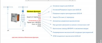
The main requirement for household electrical appliances is safety. This applies to a greater extent to devices that come into contact with water, because even a minor defect in the electrical wiring of the equipment can be fatal to the user. To protect yourself and others, it is necessary to keep the electrical network and equipment in good condition and regularly inspect them. To eliminate the possibility of a fire due to faulty wiring and electric shock, it is necessary to install protective devices (RCD).
In accordance with the basic electrical safety rules:
- The installation of temporary electrical wiring is not recommended.
- The connection of wires must be made by welding, crimping, clamping or terminal blocks. Regularly check the quality and strength of wiring connections.
- In areas with high humidity, use only certified waterproof devices.
- Electrical sockets and switches must be located at a distance of at least 500 mm from heating, gas and water supply pipes.
- Regularly check the condition of wiring and electrical equipment.
- Do not use any type of electrical equipment without a protective casing.
- Do not use homemade electrical appliances and do not repair faulty electrical equipment yourself.
This is just a short list of electrical safety requirements. More detailed information about safety rules can be found in various regulations and special literature on electricity, which are now easily found on the Internet.
What is grounding, principle of operation and device
When creating an electrical network in premises for various purposes, it is necessary to create protection that will prevent possible electric shock. To avoid this, a grounding device is installed. In accordance with the PEU clause 1.7.53, grounding is carried out in electrical equipment with a voltage of more than 50 V AC and 120 V DC.
Grounding bus from the main switchboard to the consumer
Grounding is the intentional connection of non-current-carrying metal parts of electrical installations (which may be live) with the ground or its equivalent. This protective measure is designed to eliminate the possibility of electric shock to a person due to a short circuit to the equipment body.
Operating principle
The operating principle of protective grounding is:
- reducing the potential difference between the grounded element and other conductive objects with natural grounding to a safe value;
- current drainage in case of direct contact of the grounded equipment with the phase wire. In a well-designed electrical network, the occurrence of a leakage current causes an instantaneous operation of a residual current device (RCD).
Grounding schemes in three-phase networks
From the above it follows that grounding is more effective when used in conjunction with an RCD.
Grounding device
The design of the grounding system consists of a ground electrode (the conductive part that has direct contact with the ground) and a conductor that provides contact between the ground electrode and non-current-carrying elements of electrical equipment. Typically, a steel or copper (very rarely) rod is used as a grounding conductor; in industry, this is usually a complex system consisting of several specially shaped elements.
The effectiveness of the grounding system is largely determined by the resistance value of the protective device, which can be reduced by increasing the useful area of the ground electrodes or increasing the conductivity of the medium, for which several rods are used, the level of salts in the ground increases, etc.
The grounding device is...
Above we examined in general terms what protective grounding is. However, it is worth mentioning that the grounding conductors used in the system differ in natural and artificial.
As grounding devices, it is primarily preferable to use such natural grounding devices as:
- water supply pipes located in the ground;
- metal structures of buildings and structures that have reliable contact with the ground;
- casing pipes for artesian wells;
- metal cable sheaths (with the exception of aluminum).
Option for using a pipe as a natural grounding conductor
Important! It is prohibited to use pipelines with gas and flammable liquids, as well as heating mains as a grounding element.
Natural grounding conductors must be connected to the protective system from two or more different points.
The following can be used as an artificial grounding device:
- steel pipe with a wall thickness of 3.5 mm and a diameter of 30÷50 mm and a length of about 2÷3 m;
- steel strips and corners with a thickness of 4 mm;
- steel rods up to 10 or more meters long and with a diameter of 10 mm.
Using metal strips as an artificial grounding conductor
For aggressive soils, it is necessary to use artificial grounding conductors with high corrosion resistance and made of copper, galvanized or copper-plated metal. So, we have figured out what is the definition of the concept of artificial and natural grounding, now we will look at when grounding is used.
This video clearly explains what protective grounding is:
Grounding
Let's start by analyzing each system separately.
Thus, grounding is a deliberate connection of an electrical network, device or equipment with a special structure buried in the ground through a neutral conductor.
Essentially, this is a single system that connects the conductive elements of devices and equipment (for example, their housings), the wires connected to them, and the pins buried in the ground (circuit).
Due to the high resistance of the circuit, when the phase wire touches the housing in the event of a breakdown, most of the voltage goes into the ground, and although the potential will still remain on the housing, its value will be significantly reduced and not dangerous to humans.
The international standard developed by the IEC includes several grounding systems, the differences between which boil down to different types of grounding of the power source (generator or transformer substation), and grounding of open sections of the network and devices.
The standard includes three systems - TN, TT and IT.
The first letter of the index indicates the type of grounding of the source (T - “ground”), it turns out that in the first two systems the transformer substation is connected to the grounding loop.
As for the third (IT), its power source is insulated or connected to a device that provides high resistance (I - insulation).
The second letter of the index indicates the type of grounding of open sections of the network. In the TN system (N - neutral), these sections are connected to the neutral conductor of the source connected to the ground loop (solid grounding of the neutral).
To connect equipment and devices, working (N) and protective (PE) neutral conductors are used.
As for the other two systems - TT and IT, the second letter index indicates that open sections of the network, equipment and devices are grounded by their own separate circuit.
When and where is grounding applied?
As already mentioned, protective grounding is intended to eliminate the possibility of electric shock to people in the event of voltage being applied to conductive parts of the equipment, that is, in the event of a short circuit to the housing. Protective grounding is used to equip metal non-current-carrying elements of electrical installations, which, due to a possible breakdown of wire insulation, may become energized and cause harm to the health and life of people and animals if they come into direct contact with faulty equipment.
Electrical networks and equipment with voltages up to 1000 V are subject to grounding, namely:
- alternating current;
- three-phase with isolated neutral;
- two-phase, isolated from ground;
- direct current;
- current sources with an isolated winding point.
Grounding is also necessary for electrical networks and electrical installations of direct and alternating current with voltages over 1000 V with any neutral or midpoint of the current source winding.
Electrical safety: protective grounding, protective grounding of electrical installations
Protective grounding serves to ensure the safety of people and animals when they touch metal non-current-carrying parts of electrical installations, which may become energized in the event of a phase short circuit to the body (ground). Protective grounding is the deliberate connection of metal non-current-carrying parts of electrical equipment with a grounding device, which must have a sufficiently low electrical resistance.
The operating principle of protective grounding is to reduce touch and step voltages to safe for humans during phase breakdown on the electrical equipment housing (ground). In the absence of grounding of electrical equipment housings and in the event of a phase breakdown on the housing, a person touching the housings of ungrounded equipment will be under voltage relative to the ground equal to the phase voltage of the electrical network, which is very dangerous.
In the presence of grounded electrical equipment housings, a person is connected in parallel to the grounding circuit, which has a very low resistance compared to the human body. In this case, an insignificant current will pass through a person on the “arm-to-leg” or “leg-to-leg” path, which is not dangerous to his health.
Protective grounding is used in the following electrical installations:
In 3-phase three-wire electrical installations of industrial frequency, operating with an isolated neutral of supply transformers or generators with voltages up to and above 1000V. These are electrical installations with a nominal linear voltage of electrical receivers - 220-380-680 V; 3-6-10-35 kV.
In 3-phase power frequency electrical installations operating with an effectively grounded neutral. These are electrical installations with a linear voltage of 110 kV and higher.
In electrical installations of single-phase industrial frequency current with a voltage of 220 V, working with insulated terminals of the current source.
In DC electrical installations with voltages of electrical receivers of 440 V and above - in all cases, and with voltages from 110 to 440 V - in rooms with an increased risk of electric shock to humans and in outdoor electrical installations.
Parts of power electrical equipment that must be grounded include:
• housings of electrical machines, transformers and devices;
• wires of electrical devices;
• secondary windings of instrument transformers;
• frames of distribution boards, cabinets and control panels;
• metal structures of distribution devices, metal cable structures;
• metal casings of cable couplings, metal shells and armor of control and power cables, metal shells of wires, steel pipes for electrical wires and other metal structures associated with the installation of electrical equipment;
• metal cases of mobile and portable electrical receivers.
• electrical equipment that, by the nature of its location and method of fastening, has reliable contact with other grounded metal parts of the installation, namely:
• equipment installed on grounded metal structures (in this case, cleared and unpainted areas must be provided on the supporting surfaces);
• housings of electrical measuring instruments, relays, etc., installed on switchboards, cabinets and consoles;
• removable or opening parts on metal grounded frames of any electrical structures.
Instead of grounding individual electric motors and devices on machine tools and other mechanisms, direct grounding of the frames of machine tools and mechanisms is allowed, provided that reliable contact is ensured between the body of the electrical equipment and the frame.
If performing grounding or protective shutdown that meets all the requirements of the PUE is impossible due to the conditions of the technological process (for example, in the service area of electrolysis baths of aluminum and other plants) or presents significant difficulties for any reason, then instead it is allowed to service electrical equipment from insulating areas.
The latter must be designed in such a way that touching hazardous grounded parts is possible only from these sites. In addition, the possibility of simultaneously touching ungrounded parts of electrical equipment and parts of buildings or equipment connected to the ground must be excluded.
The following are used as natural grounding conductors:
• neutral conductors of the network;
• metal structures of buildings (trusses, columns, etc.);
• metal structures for industrial purposes (crane tracks, switchgear frames, galleries, platforms, etc.);
• steel pipes for electrical wires;
• aluminum cable sheaths;
• metal stationary openly laid pipelines for all purposes, except for pipelines of flammable and explosive mixtures, sewerage and central heating.
If there are no natural grounding electrodes or their use does not give the desired results, then artificial grounding electrodes are used in the form of rods made of angular or round steel and from gas supply pipes. The choice of angle steel depends on the nature of the soil and the method of driving the rods. Gas pipes for rods are used with a diameter of 2″ in hard and medium soils and 1.5″ in soft soils; Moreover, in order to save money, substandard pipes are usually used. The length of the rods and the depth of their placement from the surface of the earth are chosen depending on climatic conditions.
Recently, for all soils, except permafrost and rocky, it is recommended to use round steel with a diameter of 12 mm for grounding conductors. The technology for quickly driving rods of this steel up to 5 m long into the ground (using electric drills and vibration) has been mastered. The use of such rods instead of angle steel rods 50 x 50 x 5 mm, 2.5-3 m long, saves time and reduces the complexity of installation work, and also provides significant savings in metal (due to the fact that a steel rod with a diameter of 12 mm and a length of 5 m, the spreading resistance is approximately half that of an angle steel rod 50 x 50 x 5 mm, 3 m long).
Round steel with a diameter of 5 mm (inside the building) and 6 mm (in the ground) is used as artificial grounding conductors; strip steel with a cross section of 24 mm2 (inside the building) and 48 mm2 (in the ground) with a thickness of 4 mm.
The grounding resistance of electrical equipment in electrical installations with voltages up to 1000 V with an insulated neutral should be no more than 4 Ohms, and with a power of generators and transformers not exceeding 100 kVA - no more than 10 Ohms. To prevent high voltage from entering the low voltage network when the insulation of the transformer windings breaks down, in these installations the transformer winding is grounded through a breakdown fuse. If high voltage enters the low voltage network, an electrical breakdown of the breakdown fuse occurs and the low voltage winding of the transformer becomes grounded.
Grounding is a deliberate electrical connection to the neutral protective conductor of metal non-current-carrying parts of installations that may be energized.
Grounding is used in four-wire networks with voltages up to 1000 V with a solidly grounded neutral. The operating principle of grounding is that when a phase is shorted to the housing, a large current (short circuit current) is created between the phase and the neutral working wire, which ensures that the protection is triggered and the damaged phase is automatically disconnected from the installation.
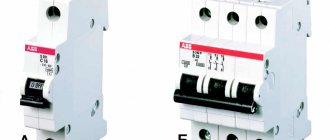
Protection may be fuses or circuit breakers installed in front of the electrical installation. Since the installation body is grounded through the neutral protective conductor and neutral grounding, the protective property of grounding is manifested before the protection is triggered.
When grounding, provision is made for re-grounding the 4th neutral working wire if it breaks in the area between the installation's grounding point and the network neutral. In this case, the short-circuit current flows through the re-grounding into the ground and through the neutral grounding to the zero point of the power source, i.e. zeroing operation is ensured.
Protective grounding serves to ensure the safety of people and animals when they touch metal non-current-carrying parts of electrical installations, which may become energized in the event of a phase short circuit to the body (ground). Protective grounding is the deliberate connection of metal non-current-carrying parts of electrical equipment with a grounding device, which must have a sufficiently low electrical resistance.
The operating principle of protective grounding is to reduce touch and step voltages to safe for humans during phase breakdown on the electrical equipment housing (ground). In the absence of grounding of electrical equipment housings and in the event of a phase breakdown on the housing, a person touching the housings of ungrounded equipment will be under voltage relative to the ground equal to the phase voltage of the electrical network, which is very dangerous.
In the presence of grounded electrical equipment housings, a person is connected in parallel to the grounding circuit, which has a very low resistance compared to the human body. In this case, an insignificant current will pass through a person on the “arm-to-leg” or “leg-to-leg” path, which is not dangerous to his health.
Protective grounding is used in the following electrical installations:
In 3-phase three-wire electrical installations of industrial frequency, operating with an isolated neutral of supply transformers or generators with voltages up to and above 1000V. These are electrical installations with a nominal linear voltage of electrical receivers - 220-380-680 V; 3-6-10-35 kV.
In 3-phase power frequency electrical installations operating with an effectively grounded neutral. These are electrical installations with a linear voltage of 110 kV and higher.
In electrical installations of single-phase industrial frequency current with a voltage of 220 V, working with insulated terminals of the current source.
In DC electrical installations with voltages of electrical receivers of 440 V and above - in all cases, and with voltages from 110 to 440 V - in rooms with an increased risk of electric shock to humans and in outdoor electrical installations.
Parts of power electrical equipment that must be grounded include:
• housings of electrical machines, transformers and devices;
• wires of electrical devices;
• secondary windings of instrument transformers;
• frames of distribution boards, cabinets and control panels;
• metal structures of distribution devices, metal cable structures;
• metal casings of cable couplings, metal shells and armor of control and power cables, metal shells of wires, steel pipes for electrical wires and other metal structures associated with the installation of electrical equipment;
• metal cases of mobile and portable electrical receivers.
• electrical equipment that, by the nature of its location and method of fastening, has reliable contact with other grounded metal parts of the installation, namely:
• equipment installed on grounded metal structures (in this case, cleared and unpainted areas must be provided on the supporting surfaces);
• housings of electrical measuring instruments, relays, etc., installed on switchboards, cabinets and consoles;
• removable or opening parts on metal grounded frames of any electrical structures.
Instead of grounding individual electric motors and devices on machine tools and other mechanisms, direct grounding of the frames of machine tools and mechanisms is allowed, provided that reliable contact is ensured between the body of the electrical equipment and the frame.
If performing grounding or protective shutdown that meets all the requirements of the PUE is impossible due to the conditions of the technological process (for example, in the service area of electrolysis baths of aluminum and other plants) or presents significant difficulties for any reason, then instead it is allowed to service electrical equipment from insulating areas.
The latter must be designed in such a way that touching hazardous grounded parts is possible only from these sites. In addition, the possibility of simultaneously touching ungrounded parts of electrical equipment and parts of buildings or equipment connected to the ground must be excluded.
The following are used as natural grounding conductors:
• neutral conductors of the network;
• metal structures of buildings (trusses, columns, etc.);
• metal structures for industrial purposes (crane tracks, switchgear frames, galleries, platforms, etc.);
• steel pipes for electrical wires;
• aluminum cable sheaths;
• metal stationary openly laid pipelines for all purposes, except for pipelines of flammable and explosive mixtures, sewerage and central heating.
If there are no natural grounding electrodes or their use does not give the desired results, then artificial grounding electrodes are used in the form of rods made of angular or round steel and from gas supply pipes. The choice of angle steel depends on the nature of the soil and the method of driving the rods. Gas pipes for rods are used with a diameter of 2″ in hard and medium soils and 1.5″ in soft soils; Moreover, in order to save money, substandard pipes are usually used. The length of the rods and the depth of their placement from the surface of the earth are chosen depending on climatic conditions.
Recently, for all soils, except permafrost and rocky, it is recommended to use round steel with a diameter of 12 mm for grounding conductors. The technology for quickly driving rods of this steel up to 5 m long into the ground (using electric drills and vibration) has been mastered. The use of such rods instead of angle steel rods 50 x 50 x 5 mm, 2.5-3 m long, saves time and reduces the complexity of installation work, and also provides significant savings in metal (due to the fact that a steel rod with a diameter of 12 mm and a length of 5 m, the spreading resistance is approximately half that of an angle steel rod 50 x 50 x 5 mm, 3 m long).
Round steel with a diameter of 5 mm (inside the building) and 6 mm (in the ground) is used as artificial grounding conductors; strip steel with a cross section of 24 mm2 (inside the building) and 48 mm2 (in the ground) with a thickness of 4 mm.
The grounding resistance of electrical equipment in electrical installations with voltages up to 1000 V with an insulated neutral should be no more than 4 Ohms, and with a power of generators and transformers not exceeding 100 kVA - no more than 10 Ohms. To prevent high voltage from entering the low voltage network when the insulation of the transformer windings breaks down, in these installations the transformer winding is grounded through a breakdown fuse. If high voltage enters the low voltage network, an electrical breakdown of the breakdown fuse occurs and the low voltage winding of the transformer becomes grounded.
Grounding is a deliberate electrical connection to the neutral protective conductor of metal non-current-carrying parts of installations that may be energized.
Grounding is used in four-wire networks with voltages up to 1000 V with a solidly grounded neutral. The operating principle of grounding is that when a phase is shorted to the housing, a large current (short circuit current) is created between the phase and the neutral working wire, which ensures that the protection is triggered and the damaged phase is automatically disconnected from the installation.
Protection may be fuses or circuit breakers installed in front of the electrical installation. Since the installation body is grounded through the neutral protective conductor and neutral grounding, the protective property of grounding is manifested before the protection is triggered.
When grounding, provision is made for re-grounding the 4th neutral working wire if it breaks in the area between the installation's grounding point and the network neutral. In this case, the short-circuit current flows through the re-grounding into the ground and through the neutral grounding to the zero point of the power source, i.e. zeroing operation is ensured.
Basic methods of grounding
When constructing a grounding system, vertical metal rods are usually used as a grounding conductor. This is due to the fact that horizontal electrodes, due to their shallow depth, have increased electrical resistance. Steel pipes, rods, angles and other rolled metal products with a length exceeding 1 meter and having a relatively small cross-section are almost always used as vertical electrodes.
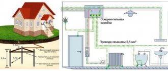
Grounding diagram in a private house
There are two main methods for installing vertical ground electrodes.
Related article:
Electricity can not only create comfortable living conditions, but also carries a certain danger. To reduce the likelihood of this danger occurring, do-it-yourself 220V grounding in a private house . How to make it - read the publication.
Several short electrodes
This option uses several steel angles or rods 2-3 meters long, which are connected together using a metal strip and welding. The connection is made at the surface of the earth. Installation of the ground electrode occurs by simply driving the electrode into the ground using a sledgehammer. This method is better known as “corner and sledgehammer”.
Using reinforcement as a grounding conductor
The minimum permitted cross-section of grounding electrodes is given in the PUE, but most often the corrected and supplemented values are from technical circular No. 11 of RusElectroMontazh. In particular:
- for corners and strips made of black steel with a cross-section of at least 150 mm2 and a wall thickness of 5 mm;
- for steel rod with a diameter of at least 18 mm;
- for steel pipes with a wall thickness of 3.5 mm and a diameter of at least 32 mm.
The advantages of this method are simplicity, low cost and availability of materials and installation.
Single electrode
In this case, an electrode in the form of a steel pipe (usually single) is used as a grounding electrode, which is placed in a deep hole drilled in the ground. Drilling the soil and installing the electrode requires the use of special equipment.
Single ground electrode mounted in a drilled hole
An increase in the contact area of the ground electrode with the ground is ensured by a greater depth of installation of the electrode. Moreover, this method is more effective in comparison with the previous option, with the same total length of the electrodes, due to reaching deep layers of soil, which usually have low electrical resistivity.
The advantages of this method include high efficiency, compactness and seasonal “independence”, i.e. Due to winter freezing of the soil, the resistivity of the ground electrode practically does not change.
Another way is to lay a grounding conductor in a trench. However, this option requires greater physical and material costs (more material, digging a trench, etc.).
This method requires a lot of physical effort.
Having figured out how grounding works and why it is needed, we now face the second question of our article, namely, what constitutes grounding, why it is needed and how it differs from grounding.
What is zeroing
The term grounding refers to the intentional connection of open non-current-carrying conductive parts of the electrical network and equipment with a solidly grounded point in single- and three-phase DC and AC networks. Grounding is performed for electrical safety purposes and is the main protective measure against voltage.
Grounding for three- and single-phase electrical networks
Operating principle
A short circuit in the electrical network occurs when an energized phase wire comes into contact with the body of the device connected to zero. The current increases sharply, and protective devices are activated, cutting off power from the faulty equipment. According to the rules, the response time of the RCD to disconnect a faulty electrical network should not exceed 0.4 seconds. To do this, it is necessary that the phase and zero have an insignificant resistance value.
Related article:
Have you ever heard the abbreviation RCD? what it is by reading the review to the end. Briefly, I would like to add that this device is capable of protecting housing and all its inhabitants from emergency situations related to electricity.
Grounding circuit
To create a grounding in a single-phase network, as a rule, the third (unused) wire of a three-core cable is used. To create good protection, it is necessary to ensure a high-quality connection of all elements of the grounding system.
Device
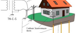
The grounding system, for example, in an apartment building, begins with a grounded power transformer, from which the neutral with a three-phase line comes to the main distribution board (MSB) of the building. Next, wiring occurs to the floor electrical panels. A working zero is created from the neutral, which, together with the phase wire, forms the usual single-phase voltage.
Scheme of the grounding device from the substation to the apartment
The grounding itself to protect the electrical network and equipment is created in the panel using a conductor connected to a grounded neutral. You should know that it is forbidden to install switching devices (automatic machines, packets, switches, etc.) between zero and neutral.
Where is the zeroing scheme used?
According to the requirements of the PES, the following must be equipped with protective grounding:
- single- and three-phase AC networks with a grounded terminal and voltage up to 1,000 V;
- DC power networks with a central grounding point and voltage up to 1,000 V.
Grounding cannot protect against electric shock like grounding. This protective circuit simply cuts off the voltage supply in the event of a short circuit and turns off the local power grid.
Grounding and zeroing, their fundamental difference and what is better to use in the house
Surely most of you have heard about such a concept as grounding, and even more so about protective grounding. Do you know how they differ and what is better to use in the house? If not, then in this article I will explain to you the fundamental difference between these two systems and tell you what it is advisable to use in your home.
What's the difference
Protective grounding is designed to prevent a person from being exposed to dangerous current values when a leak occurs. Simply put, if a current appears on the body of an electrical device, it will immediately go to the ground and the person who touches such a device will not be shocked.
Moreover, you can implement grounding yourself and without serious financial costs. After all, it’s enough to take a welding machine, a shovel, several fittings, a strip of metal and a copper wire. And your outline will be ready. After that, we connect it to the three-wire network of your home and that’s it, protection is provided.
And grounding is the connection of the ground with the working zero. In the event of the same insulation breakdown, it causes a short circuit and, as a result, shutdown of the circuit breakers.
And it is simply impossible to carry out zeroing in the house without calling a specialist, who will calculate and select a special point.
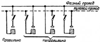
For clarity, carefully examine the diagram; it shows the difference between grounding and grounding in a simple form.
What to choose for your home
Here I will say and outline my position: I am categorically against the use of nulling, since this method is a potentially delayed danger. After all, even if you very carefully and regularly check the integrity of the zero, there is still a possibility that as a result of unforeseen circumstances the phasing will be changed and the zero will turn out to be a phase. In this case, absolutely all electrical appliances plugged into the network will be energized, and this can lead to very disastrous consequences.
A zero break may also occur, in which case the system will be ineffective, again you will be at risk of electric shock.
Protective grounding in this regard is several orders of magnitude more reliable and it will be sufficient to inspect the bolted connection no more than once a year. And for many years you will be provided with reliable protection.
zen.yandex.ru/media/energofiksik/
Is it possible to ground in an apartment using grounding?
We already know what grounding and grounding are, and we’ll try to find out whether it’s possible to do grounding using a grounded zero located in the electrical panel. The fact is that many people far from electrical engineering ask this question and often make unforgivable mistakes by doing just that.
Firstly, this is prohibited by PEU. The fact is that if, for example, during installation work, for some reason the phase and zero are mixed up, and besides, the zero is brought to the working zero, then you can expect the most unpleasant situations. When electrical equipment is connected to the network, the housing will be energized and a person will be shocked by an electric shock, since the protective operation of the RCD will not occur.
To create a protective grounding in the floor electrical panel, a separate bus is allocated, connecting to a solidly grounded neutral. And it is best not to carry out this work yourself, but to entrust it to a specialist who has knowledge in electrical engineering.
The video shows how to create a grounding if it is not in the floor electrical panel:
TN-C grounding system
There is nothing new in this design. She was like this for many years.
It uses 4 wires to power consumers. Three of them are phase, one is zero. The latter carries the operating load current. But it is also used for protective purposes, connecting to the neutral grounding circuit of the power transformer that supplies electrical installations. Electrical equipment housings are also attached to it. It is called a PEN conductor. Due to the fact that it combines the functions of protection and transport of operating current to its destination, it is called a “combined conductor”.
As a result, both tasks are realized: the ground fault current is high - the damaged section is disconnected quite quickly. In addition, if damaged, the low resistance of the PEN conductor shunts the body of the person touching the body, which has a resistance of the order of a kilo-ohm. Most of the current flows into the ground.
But the operating load current flows through the PEN conductor. As a result, contact connections may be disrupted, the connection may become unreliable or be interrupted altogether.
This eliminates the much-needed connection to the grounding device.
Even if there is re-grounding of the PEN conductor at the entrance to the building.
Moreover, the presence of current in this conductor leads to the emergence of a potential that increases with distance from the point of connection with the ground loop.
And if the PEN conductor breaks, the picture is completely terrifying. The potential on the housings behind the break point can theoretically reach 220 V.
Let's add to all this the technologically difficult implementation of connecting the housings of some electrical receivers with PEN. How to ground the body of an electric stove connected to the network through an outlet?
The development of household electrical appliances requiring the use of protective measures for electrical safety has led to the improvement of the TN-C system. You can read more about the TN-C system in a separate article.
Grounding system TN-S
The difference from the previous considered grounding system is that the functions of the working-zero and protective conductor are separated in different physical conductors. Zero operating (N) - conducts the load current, zero protective (PE) - connects to the ground loop.
As a result, there is a complete elimination of potential on buildings that appear in “particularly remote areas” of the electrical network, as well as in the event of conductor breaks. The maximum that threatens in the absence of the integrity of the PE conductor is lack of protection. But it has little chance of breaking - no current flows through it, why would it suddenly get lost in contact connections made in accordance with all electrical rules?
Since the cross-section of PE conductors in cable lines is usually equal to the cross-section of phase conductors, the task of connecting them to the housings of any electrical equipment has been simplified.
Even to the grounding contact of the socket. This made it possible to extend protective safety measures to all household electrical appliances: the same electric stove, in particular.
True, an extra core was added to the power cable lines. Well, you have to pay for security.
All newly installed electrical installations are now, as a rule, carried out using this grounding system.
You can read more about the TN-S system in a separate article.
Grounding system TN-CS.
A significant problem when implementing the TN-S system is that the reconstruction of electrical installations and the construction of new ones often occurs without reconstruction of the transformer substation itself. Usually some part of it is redone, starting from the switchboard at the input to the last consumer. Before this shield, the grounding system inevitably retains the old design.
This problem was solved in advance by the same paragraph of the PUE, which describes the transitional version of the grounding system, designated as TN-CS. In it, the part of the electrical installation that was untouched by reconstruction does not officially change its structure, remaining the same TN-C. But from a certain point, the distribution network follows the new rules.
What is the difference between grounding and grounding?
It’s worth saying right away that despite the fact that grounding and grounding are protective measures, they differ in their principle of operation and purpose. Grounding is a more effective and reliable method of protection than grounding, since it allows you to quickly equalize the difference between potentials to the required value. Also, grounding has a simpler design and is easier to install, and to install it you just need to follow the instructions. In addition, this protective circuit does not depend on the phase pattern of the connected equipment. Grounding options are varied, and this allows you to choose a specific type for each specific case
Difference between grounding and neutralizing
Protective grounding is a protective measure that, in the event of a network malfunction, simply ensures an instantaneous interruption of the supply of voltage from the electrical network by triggering an RCD. Creating grounding and connecting equipment requires experience and certain knowledge in electrical engineering. All installation work, especially determining the zero point, must be performed correctly, otherwise, in an emergency, electric shock may occur.
Having figured out what grounding and grounding are, many people prefer to use both methods. However, grounding is mandatory when installing household and industrial networks, as well as operating equipment.
To better understand the difference between grounding and zeroing, we suggest watching this video:
The difference between grounding and zero
The main difference between grounding and neutralizing is the purpose of the systems. Grounding is needed to quickly reduce the voltage to an acceptable level. The task of zeroing is to completely turn off the current in the area where a breakdown occurred on the housing or other non-current-carrying element. Zeroing is associated with a decrease in the potential of the housing during the period between the circuit and the power supply being cut off.
Grounding is not used in new buildings. In new buildings, a 3-wire cable with phase, neutral and ground is laid (1-phase system) or a 5-wire cable (three phases, neutral and ground) in a 3-phase system. The most commonly used circuit is TN-S, but TN-CS is also found.
Requirements for grounding and grounding
Grounding is a more serious protective measure than grounding. This scheme requires the creation of a separate low-resistance busbar, which is connected to a ground electrode buried in the ground and arranged in accordance with the standards. All requirements for grounding, its elements and arrangement are specified in the PEU and GOST 12.2.007.0.
Installations with isolated neutral
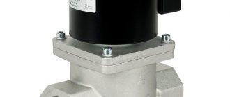
In the industrial sector the following must be grounded:
- electric drives;
- electrical equipment housings;
- metal structures of buildings;
- shielded braiding of low-voltage electrical cables;
- housings of electrical distribution panels and similar structures.
More flexible requirements are imposed on zeroing, namely:
- neutral and phase conductors are selected in such a way that, in the event of a breakdown, a current sufficient to trigger an RCD or other protective mechanism appears on the equipment body;
- The grounding conductor from the device to the grounded neutral must be continuous, that is, it must not contain any switching devices in the circuit.
Let's sum it up
Ensuring the safety of life and health is the primary task of the state, society and, naturally, the individual himself. To do this, you must strictly adhere to the established rules, instructions and requirements. One of the factors dangerous to human health is electricity, so it is very important to ensure sufficient electrical safety at work and at home using certain measures and protective technical means.
If you still have questions about this topic or have new ones, write in the comments, our team will try to answer them.
There are no publications on the topic.