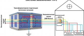
Grounding concept
Grounding (Pe) is the connection of an electrical installation to a set of devices that ensure current flows into the ground.
It is divided into 2 types:
- Working. Plays the role of a neutral in the electrical circuits of powerful installations - arc arresters, arresters, transformers, generators, etc. In everyday life, a Pe system is considered to be a working system, to which a surge protection device is connected. It is customary to include grounding of lightning rods in this category.
- Protective. Prevents people from getting electrocuted. Valid only in emergency situations.
Device
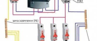
The system includes:
- Ground electrode. 1 or several electrodes made of conductive material driven into the ground. In the second case, they are connected by a common bus.
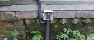
- Circuit. A metal structure laid inside a building, to which electrical installations are connected directly or through a special contact in a socket. In most cases it is made of steel strip.
- Connecting bus. Provides electrical connection between the circuit and the ground electrode. Basically, it is also made from steel strip.
Grounding ensures current flows into the ground.
Principle of operation
The operation of the system is based on the ability of the soil to absorb an electrical charge like a capacitor with infinite capacity. Protective grounding involves shorting metal non-current-carrying parts of the installation to the ground - the housing (most often), fencing, etc.
If any of these elements is energized, it will remain safe for humans, because the current will flow along the path of least resistance - to the ground. And if the installation is also powered through a residual current device (RCD), then at the moment the housing contacts the live part it will be de-energized, which completely eliminates the possibility of electrical injury.
What is grounding?
Protective grounding is the intentional connection to ground of those parts of electrical equipment that, during normal operation of the electrical network, are not under the influence of voltage, but may come under its influence as a result of an insulation breakdown. The main purpose of grounding is to protect people from electric current.
The main component of protective grounding is the circuit. It is a design of natural or artificial grounding electrodes, that is, several grounding electrodes are connected into a single whole. Steel rods are most often used as electrodes. Copper rods are used less frequently due to the fact that they are expensive.
But if you have the financial means, keep in mind that copper is the ideal option and the best conductor.
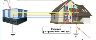
Logically, it is clear that the ground loop should be located in the ground. Since we are interested in protecting the house, a suitable place with normal soil is selected not far from the building and power panel. Three pins are driven into the ground so that they are arranged in a triangle, and the distance between them is 1.5 m.
Now you will need a welding machine and a metal bus, with the help of which the electrodes need to be tied together into an equilateral triangle. The circuit is ready, now you need to attach a copper conductor to it, which then goes into the shield and is connected there to the grounding busbar. And the grounding conductors from all sockets are output to this busbar.
Before use, it is necessary to check the circuit for grounding resistance.
The following video explains what grounding is:
The need to check parameters
In a situation where a person touches a live body, he and the grounding conductor act as parallel-connected conductors.
The ratios of their resistances and the currents flowing through them are inversely proportional:
I1/I2 = R2/R1
The lower the grounding resistivity, the smaller the amount of charge passing through a person.
For the home electrical network, the PUE sets the following maximum permissible values (clause 1.7.97):
- with the total power of simultaneously operating electrical receivers up to 100 kVA - 10 Ohms;
- more than 100 (kVA) – 4 Ohm.
The ground electrode protrudes parallel to the conductors.
With the presence of an RCD, the reliability of the system increases. To de-energize an emergency installation, it is only necessary that the current leakage through the conductor Pe exceeds 30 mA (sensitivity threshold of the switch). But this does not affect the requirements for grounding resistivity.
The PUE specifies the parameters of other types of the Pe system:
| Device | Maximum permissible grounding resistance, Ohm |
| Lightning rod | 10 |
| Telecommunication systems | 2 |
| Server equipment | 1 |
| Working grounding of electrical installations | 4–10 |
The system resistivity Pe may increase over time.
The spread of current in the ground is prevented by:
- corrosion of the ground electrode and contacts between system components;
- dry soil;
- a change in its composition, for example a decrease in salt concentration.
Therefore, the system resistance must be checked periodically.
Effect of corrosion on grounding elements
Devices used
To measure grounding parameters, use:
- ampere and voltmeter;
- current clamps, for example brands S.A 6412, IS-20/1M, S.A 6415, S.A 6410;
- special metrological instruments of high accuracy classes based on an ohmmeter.
An ammeter is used to measure grounding parameters.
Classic representatives of the latter group are analog devices of the following brands:
- ISZ-2016;
- MS-08;
- F4103-M1;
- M-416.
Modern digital models with a processor, a function for storing measurement results, etc. are more accurate and easier to use.
Other dimensions
For a comprehensive examination of the current grounding condition and in accordance with generally accepted test standards, other measuring procedures are allowed simultaneously with resistance measurement, namely:
determination of the value of touch voltage (for power plants);- checking for breaks in the entire chain of elements, starting from the grounded device and up to the ground electrode;
- measuring the so-called “short-circuit currents” of power plants and examining the condition of their breakdown elements (fuses);
- determination of the resistivity of the soil layer in the area where ground electrodes are placed.
If necessary, other types of measurement tests can be carried out to examine the characteristics of grounding conductors installed in protective circuits.
Basic rules and techniques for measuring grounding
All methods for assessing the state of a system are based on Ohm's law for a section of a circuit. Knowing the voltage U of the source to which the ground is connected, measure the current I flowing in it and calculate the resistance using the formula:
R = U/I
The following methods are used:
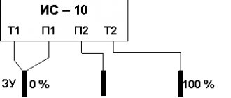
- Ampere and voltmeter. The simplest, but also the least accurate. 2 electrodes are driven into the ground 20 m from the ground electrode and connected to a calibrated voltage source. Then the current strength is determined with an ammeter, and the potential drop in the area of interest is determined with a voltmeter and calculations are made.
- Compensating 3-wire. Involves the use of special meters such as M-416. 2 electrodes are also driven into the ground, but on both sides of the ground electrode, then the device is connected to them. There is no need to make calculations - the system resistivity Pe is read on the scale. The device also allows you to measure soil resistivity. To do this, use the 4-wire method.
- Using 2 current clamps. Measure the background current from the electrical installation to the ground. The method allows you to do without additional electrodes and disconnecting the Pe circuit, i.e. chain break.
Grounding measurement techniques are based on Ohm's law.
The choice of method depends on the operating conditions of the equipment.
Technology for working with the M-416 device
Work with the meter begins with calibration:
- Place it on a flat horizontal surface.
- Set the range switch to the “Control” position.
- Press the red button and rotate the slider handle so that the arrow points to “0”.
The scale of a working device will display “5 Ohms”. The permissible deviation is 0.3 in both directions.
Then proceed in this order:
- De-energize the network in the building or disconnect the Pe conductor from the installation.
- The clamp is connected to the device with a cable.
- Drive 2 electrodes into the ground. Minimum depth – 50 cm.
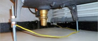
- Clean the junction of the bus and the ground loop from paint and rust.
- Connect the electrodes and ground electrode (using a clamp) to the device in accordance with the diagram shown on the inside of the cover.
- Set the range switch to the desired position. For example, for resistances up to 10 Ohms - “x1”.
- Rotate the slider knob to set the arrow to “0”.
- Take readings from the scale and multiply by the number to which the range switch is set.
- In the same way, several more measurements are taken to check, slightly changing the position of the electrodes.
To begin work, de-energize the network in the building and disconnect the conductor.
The procedure is completed correctly if all results differ from one another by no more than 5%.
Measurements are carried out in summer in stable dry weather, when the soil has maximum resistance.
Installation of a new grounding device
Inspection, testing and testing of grounding devices also includes the study of documentation, including hidden work: installation certificates, measurement reports, as-built drawings and other technical documentation. They must indicate the location, configuration and potentials of all grounding devices and lightning protection elements. If it is necessary to rework or change the grounding device, or install a new one, it is necessary to recalculate the joint operation of the storage network in order to avoid conflicts between devices. A new grounding device must be installed not only to reduce the regular high resistance: according to expert calculations, every 10 years steel structures lose up to 2.5 mm of thickness in the ground, therefore, if the grounding device is made of strip steel 5 mm thick, then it is obvious that corrosion will be more than 50% and the electrode will require replacement. However, you don’t need to wait all 10 years - if half of the useful mass is lost, the electrode is already considered inoperative. In general, calculating the timing of replacement of grounding devices is quite easy to do - based on the thickness of the element and the corrosion coefficient. Thus, for steel, the replacement period will be a number of years equal to the thickness of the strip. With a thickness of 8 mm, replacement should occur after 8 years, 4 mm - 4 years, 5 mm - 5 years. These are recommended periods, although grounding electrodes can operate longer, losing a certain percentage of efficiency every year, which increases the risk of ineffective grounding in an emergency. In the example given, we used strip steel, but the aging of angle steel, round steel or pipes can be calculated similarly.
To find out exactly whether it is necessary to change the ground electrodes, it is enough to measure the amount of corrosion of the elements of the grounding device and use the recommendations of the Normative Document. If it is 50% or more, it is recommended to replace it immediately. According to the recommendations of experts, “inspections with selective opening of the soil in places most susceptible to corrosion, as well as near the grounding points of power transformer neutrals, connections of arresters and surge suppressors should be carried out in accordance with the schedule of planned maintenance work (hereinafter referred to as PPR), but not less often once every 12 years. The size of the section of the grounding device subject to selective excavation of the soil (except for overhead lines in populated areas) is determined by the decision of the technical manager of the consumer based on the requirements of the RD.”
The nuances of checking grounding in sockets
The presence of a Pe connection can be checked with available tools, without the help of professionals. Several methods are used.
Multimeter
Switch the device to the alternating voltage (AC) measurement mode of approximately ~220 V.
Then proceed in the following order:
- Using an indicator screwdriver, determine which terminal of the socket the “phase” is connected to (the light on the indicator will light up).
- Measure the voltage between this contact and “zero” with a multimeter.
- Disconnect the instrument probe from the neutral. Touch it to the ground terminal and take readings again.
The following situations are possible:
- The measurement results in step 3 are the same as in step 2 or a little less - the grounding is working properly.
- There is a significant difference in the readings - the Pe system has extremely high resistance.
- In step 3, the device showed “0” - there is no contact with ground.
The multimeter is switched to AC voltage measurement mode.
Indicator light
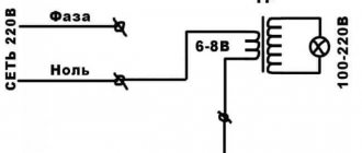
Create a makeshift tester:
- screw the light bulb into the socket;
- Solder a piece of copper wire to its contacts.
Touch the “phase” terminal with one “probe” and the ground terminal with the other.
The following situations are possible:
- The light is bright - the Pe system is working.
- The light is dim – there is contact, but the system resistivity is extremely high.
- Off – Pe is missing.
If an indicator screwdriver is not available, apply one probe to the Pe terminal, and use the others to check the remaining two in turn.
Make a makeshift tester out of a light bulb.
If the light does not light in both cases, check the functionality of the socket.
To do this, the wires touch the terminals to which the “phase” and “zero” are connected.
Indirect evidence of the absence of Re
The following signs indicate grounding failure:
- water heater, washing machine or dishwasher electrocutes;
- When playing music, the speakers make extraneous noise.
Testing with a digital voltmeter
You need a device to measure alternating (AC) voltage. Pointer models are analog and do not require power.
Digital ones operate on rechargeable batteries or batteries and have the following advantages:
- data is displayed on the display, which makes it easier to read and increases the accuracy of measurements;
- the performance of the device does not depend on orientation in space;
- measurement results are stored in memory.
Digital voltmeters operate on batteries.
The switch is set to a range that includes 220 V. When using a pointer device, the wires from the probes are screwed to the corresponding contacts. Next, check in the same way as with a multimeter.
Why is grounding checked?
Checking the grounding condition is an important measure aimed at protecting people from electric current. To solve the problem of how to check grounding in a private house, special equipment is used. The results obtained make it possible to determine the state of the grounding, whether it complies with established standards and whether it is capable of performing its functions. Typically, such measurements are carried out by qualified specialists from the organization servicing the home network.
Periodic grounding checks must be carried out, despite the fact that all electrical equipment in the house was installed by professional electrical technicians. There are often cases when incorrect connection of the circuit causes its premature wear. In this regard, it is recommended to measure and check in a timely manner the condition of the soil and the electrodes placed in it, as well as grounding conductors, busbars and metal bonding elements.
This procedure, which determines whether there is grounding, is carried out in residential buildings at least once every 3 years, and at industrial production facilities - annually.
During the measurement process, the tester determines the resistance of the circuit, the value of which must correspond to the established standards. If the indicators are higher than the norm, they can be reduced. To do this, you simply need to increase the interaction area by adding electrodes or raising the total conductivity of the soil by increasing the concentration of salts contained in the soil.
It should be borne in mind that a conventional grounding device can only reduce the voltage supplied to the equipment frame. A residual current device - an RCD, installed in conjunction with grounding, will help make protection more reliable. Any protective equipment is designed and selected individually, in accordance with operating conditions. The choice is made taking into account humidity, soil structure and other factors.
It is also necessary to remember that many types of modern electrical devices are equipped with a built-in RCD, which is triggered only when plugged into a grounded outlet. Therefore, their normal operation depends entirely on the correct connection of the protection and further checks of its functionality.
Testing in an apartment or private house yourself
The scope of work to check Pe in a city apartment and a cottage is different.
In the first case, perform the following actions:
- Check the functionality of the outlet by plugging in a table lamp or other known working device.
- They cut off power to the apartment.
- Remove the decorative panel from the socket and look at how many cores are in the supplied wire and how the Pe terminal is connected.
The cable must have 3 cores. It is customary to connect the Pe terminal to the one with yellow-green insulation.
If a visual inspection confirms the presence of grounding, return the decorative panel to its place, apply power to the network and check the Pe system using any of the described methods.
In a city apartment, the functionality of the outlet is checked.
The owner of a private house needs to additionally check the resistance value of the ground electrode. To do this, call specialists with the appropriate equipment.
Briefly about inspections
According to PTEEP, the frequency of inspections of grounding loops (grounding devices) should be once every 6 years. A visual inspection of visible parts of the device should be carried out once every six months. Checks can be carried out more often, especially if there is a suspicion of a malfunction of the grounding equipment.
Ground resistance testing is usually carried out in conjunction with other tests. Its task is to evaluate the protective properties of electrical equipment.
The inspection can be carried out by special organizations that have permits for such work, are certified by the Ministry of Energy, and have special laboratories and instruments for carrying out measurements. Employees must undergo appropriate training, occupational safety knowledge testing, and a medical examination.
For your information! A grounding device (grounding loop) is necessary to protect workers from electric shock due to breakdown of electrical equipment. If the system is operating, current will flow through the ground electrode for a short period of time. And a dangerous situation will not happen at the enterprise
Therefore, it is important to monitor the condition of grounding devices
Solving connection problems
If checking Pe shows that it is not working, do the following:
- Check the functioning of the network by plugging any device into the outlet.
- If it works, remove the plug and de-energize the apartment using the machine in the panel.
- Disassemble the socket and check the connection of the wires to the terminals.
If the contact is broken due to a broken conductor, the connection is restored. If there is no visible damage, call an electrician.
Useful tips and general recommendations
During work, observe the following rules:
- Use dielectric gloves and a mat, and a tool with insulated handles. Do not stand on wet floors.
- Before carrying out installation or repair, disconnect the power from the network.
- Check the functionality of the indicator screwdriver on the contact in the input panel. He's always energized.
- Place the analog (pointer) device on a flat horizontal surface to avoid the pointer moving under its own weight.
- Do not use pipelines or other metal structures not intended for this purpose as grounding. This may result in electrical injury to other occupants.
Independent actions are permissible only if the performer clearly understands what needs to be done. If you have the slightest doubt, call a professional, because... manipulations with the electrical network by an unqualified person can lead to serious consequences, including the death of one of the residents.
Registration of results
Based on the results of the entire set of tests performed, a protocol for checking the grounding device is drawn up, which must indicate the measured grounding parameters and provide recommendations for further operation of the system.
The need to organize and carry out a full range of measuring activities most often arises after the completion of reconstruction or repair of the entire grounding system. In some cases, verification tests are carried out after serious violations of operating rules are detected.
The values of standardized performance indicators of such systems (soil conductivity and installation resistance to spreading current) for various types of neutral grounding are given in Table 36 of PTEEP (Appendix 3.1).
Systematic testing of grounding functionality guarantees effective protection of the consumer from electric shock and ensures complete safety of operation of any type of electrical equipment.