Terms of use
When starting to work with a voltage indicator, you need to make sure that it is intact and operational. The potential difference for which it is intended must be higher than the operating voltage of the electrical equipment being tested. The indicator's next laboratory test date must not be past due.
Before working with a low voltage indicator (LVI), it must be checked for functionality. To check, you can use a connected socket with a voltage of 220 V. A single-pole indicator should determine the phase, and a two-pole indicator should determine the presence of 220 V.
To check the high voltage indicator (HVI), its probe is brought closer to parts of the electrical installation to which high voltage is applied. The alarm should sound. All operations with UNN must be done with dielectric gloves.
Some work in the house can be performed by people without special training, without resorting to the services of professional electricians. Replacing sockets, switches, and repairing table and ceiling lamps do not require high qualifications.
But when performing this work, you must follow safety rules, which require checking that there is no voltage at the contacts of electrical appliances before starting work.
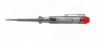
Single-pole voltage indicator
- the simplest and most accessible device for everyone, indicating the presence or absence of a “phase”. Some models are also used to search for breaks in wires, cords and cables. Since some single-pole indicators combine the function of a simple screwdriver, they are called “indicator screwdrivers”, and sometimes simply “indicators”.
The advantage of indicators is that they do not require a second wire to operate. They use current passing from "phase" to "ground" through the pointer and the human body, connected in series. This current does not pose a danger to humans. It is not hampered by the resistance of shoes or the floor material, but you cannot use the pointer while wearing dielectric gloves; it will not work. In practice, there were isolated cases when the indicator screwdriver did not detect the presence of a “phase” in the lamp if the electrician was standing on a dry wooden stepladder.
Digital multimeter tester: how to use the device
This device is an improved version of the active indicator. This is a voltage measuring tester. It can also be used as a regular device. Professionals call this tool a “multimeter” because it can perform several functions:
- indicate the presence or absence of voltage;
- determine the current strength and resistance value.
Such testers have switches that adjust the sensitivity level. The device can be used for contact and non-contact methods of detecting the presence of voltage and voltage.
The device, in addition to the light, is also equipped with a sound signal. The design has a digital display that displays the measurement indicators.
Important! It is easy to purchase additional pliers for the multifunction tester, which can be used to determine the current strength without removing the insulating layer.
The digital multimeter tester is equipped with an electronic display
To confidently understand how to find phase and zero with an indicator screwdriver of this type, you need to carefully study the description of the device and instructions. Some models, in addition to the above functions, can check the temperature of equipment under the influence of current. Such capabilities are important for those who control the operation of electrical switchboards, electric motors, etc.
Almost all modern houses are equipped with cabinets from which electrical cables are routed. And relatively powerful engines are not uncommon on the farm. Therefore, a multifunctional tester is often needed in everyday life, and not a simple indicator screwdriver.
AC and DC voltage indicator up to 600 V
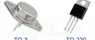
The next option is a slightly more complex system, due to the presence in the circuit, in addition to the elements already known to us, of two transistors and a capacitance. But the versatility of this indicator will pleasantly surprise you. It can safely check the presence of voltage from 5 to 600 V, both direct and alternating.
The main element of the voltage indicator circuit is a field-effect transistor (VT2). The threshold voltage value that will allow the indicator to operate is fixed by the gate-source potential difference, and the maximum possible voltage determines the drop at the drain-source. It functions as a current stabilizer. Feedback is provided through a bipolar transistor (VT1) to maintain the set value.
The operating principle of the LED indicator is as follows. When a potential difference is applied to the input, a current will arise in the circuit, the value of which is determined by the resistance (R2) and the voltage of the base-emitter junction of the bipolar transistor (VT1). In order for a weak LED to light up, a stabilization current of 100 μA is sufficient. To do this, the resistance (R2) should be 500-600 Ohms, if the base-emitter voltage is approximately 0.5 V. A capacitor (C) is required to be non-polar, with a capacity of 0.1 μF, it serves as protection for the LED from current surges. We select a resistor (R1) with a value of 1 MOhm; it acts as a load for the bipolar transistor (VT1). The functions of the diode (VD) in the case of DC voltage indication are pole testing and protection. And to check the alternating voltage, it plays the role of a rectifier, cutting off the negative half-wave. Its reverse voltage must be at least 600 V. As for the LED (HL), choose so that its glow at minimum currents is noticeable.
Types of devices
Indicators up to 1000 volts and above 1000 volts have different external and design features. For low-voltage measurements, up to 1 kV, there are two types of devices:
- single-pole, responsive to the flow of capacitive current;
- bipolar, gives an indication when active current flows through it.
The single-pole indicator is designed to work in alternating current circuits, to detect phase conductors, in lighting circuits, when phasing an electric meter, and checking cartridges in lamps. Simply put, to detect live wires.
Single-pole phase indicating devices have the same design and typically consist of a gas-discharge indicator lamp, with an ignition threshold of 90 to 120 volts, and a 1 MΩ resistor connected in series. The resistor limits the current to a safe value, about 0.5 mA.
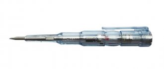
The IN - 90 indicator is made in the form of a screwdriver.
The disadvantages of such indicators include low sensitivity (the indication threshold of some devices starts at 90 volts), as well as sensitivity to interference in neighboring wires.
For networks above 1000 volts, voltage indicators are made with handles made of insulating material and long, preventing a person from approaching current-carrying elements. The appearance of the UVN-10 is shown in the photo below:
When measuring voltages above 1000 volts, they resort to the use of additional protective equipment: rubber gloves, boots or an insulating mat. You can find out from our article!
A two-pole indicator consists of two housings made of insulating material and a flexible insulated copper conductor that connects them. Diagram of a two-pole voltage indicator type UNN-10:
In this circuit, the gas-discharge indicator is shunted by a resistor, which makes the circuit insensitive to induced voltages. Also based on it, an indicator with a voltage indicator UN-1 is produced:
This device uses a special linear gas-discharge lamp and a scale on the body with graduations of 127, 220, 380, 500 Volts.
There are also universal voltage indicators for checking the presence of voltage and indicating its value from 12 to 380 V. For operation in DC circuits, up to 500 volts, and alternating current, up to 380 volts. They can additionally be used to test the integrity of connections.
These devices use LEDs as light indicators, and a large capacitor as a power source.
The digital voltage indicator has an LCD screen with printed values in volts. At a maximum value of 220 volts, all values from minimum to maximum are displayed on the screen. Those. This tester shows an approximate value. The only advantage of this model is the lack of a power source.
Non-contact indicators are designed to detect live conductors, including those hidden in walls or panels. The circuitry of this device responds to an alternating electromagnetic field and is equipped with light and sound indication. We talked more about these devices when we talked about .
Classification
Each UN has a different cost, since according to its quality characteristics it belongs to a certain technical group. The group is determined based on qualities and tests, as indicated in a special protocol attached to the device. The following groups are distinguished:
- Based on indicators:
- up to 1,000 V;
- above 1,000 V.
- By number of poles:
- single-pole - single-pole devices have a gas-discharge indicator lamp, an additional resistor, 2 electrodes - in the form of a tip and a manual contact. At the lower end of the body there is a metal probe for touching the network.;
- bipolar - the bipolar also has lugs (2 pcs.), up to 7 mm in length; when checking the voltage, one contact is connected to one phase of the electrical installation, and the second to the other, carrying current in the circuit, the signal light will light up: with alternating - 2 lamps, and with constant – with the index “+” or “–” (according to polarity).;
- Universal:
- alternating current;
- at constant current.
- According to the indicator:
- neon;
- LED;
- acoustic;
- digital.
- Contactless.
A single-pole indicator can be purchased from 205 rubles to 2200 rubles. A two-pole UN costs from 170 rubles to 2700 rubles. Universal signs are sold from 615 rubles, and contactless signs – from 690.
Single-pole voltage voltages are easy to use, resemble a screwdriver or a pen in appearance, and are suitable for ratings up to 1000 V, used for installations with alternating current. The disadvantage of the device can be considered the inability to check the network with direct current. Such devices include, for example, INO-70, UNN-90.
A two-pole UN has 2 component dielectric parts and a copper conductor-connector. The device is suitable for testing AC and DC networks. To do this, touch two parts of the installation. The device is produced by manufacturers in the form of various compact models. The LED scale shows values up to 1000 V. For example, UNN “Kombi” uses LEDs as an indicator. In this case, the power source is a capacitor with a large capacity. Such a UN also gives a sound signal. The most popular two-pole device is also Pin 90M.
All indicators above 1000 V are considered high voltage and monitor alternating current indicators when touching a phase. This device does not have contact pads and is used for large electrical installations. For example, a portable UVN is intended for testing installations with a voltage of 35 kV.
Also read: How many watts are in one kilowatt
Universal pointers are used to control zero and phase. The indicators for them are LEDs, and the voltage source is a high-capacity capacitor. Such devices are indispensable for electricians and production workers, as they allow you to check the connections of different electrical circuits in the absence of a power source.
When applied to a wall, a non-contact UN perceives an electromagnetic alternating field. It makes it easy to determine the voltage without touching exposed parts of the electrical network. The device has sound and light indicators. Digital devices have an LCD with values that are displayed on the screen.
IMPORTANT! There are also UN that determines low voltage (PIN-90), its values cannot be more than 50-90 V.
Double pole design
A high voltage indicator with two measuring contacts works on the principle of detecting the passage of current through a section of the circuit. An internal circuit compares the potential difference between the measuring point and ground (or neutral contact). If the response threshold exceeds the set value, an indication is triggered.
The design may be different, depending on the purpose: indication only, search for breakdown, measurement of the exact voltage value, setting the range (220 V, 380 V). As an example, the illustration shows an electrical circuit of a device that determines the presence of a phase in the measured area and an approximate voltage threshold.
There are no complex integral elements, so this indicator is reliable and trouble-free under any operating conditions. If measurements are taken outdoors, in bright light - parallel to the light indicator (in this case, an LED element), a sound is added.
By adding a voltage measurement module to the measuring circuit, we get a single-mode multimeter designed for safe high voltage measurements.
Using such a device is not difficult: the passive contact on the connecting wire is applied to the ground (zero) bus of the electrical installation. Then the measuring contact must touch the potential measurement point.
Advantages:
- high measurement accuracy, functionality can be expanded if necessary;
- ability to work with high voltage without additional operator protection equipment;
- operator protection is ensured: there is no direct contact with open areas of the body.
Flaws:
- higher cost;
- The meter is quite bulky.
Single-pole voltage indicators
Just like they require touching only one live part. “Earth” in this case will be provided through the body of a person, who, by touching a special contact of the voltage indicator, closes the current flow circuit. As a result, an electric current flows through a person, which does not exceed 30 mA and is safe for his life and health.
Such voltage indicators are usually made in the form of automatic pens. Their body has an inspection hole and is made of insulating materials.
The housing, as you probably already guessed, contains a resistor and a signal lamp. A metal flat contact is attached to the upper end of the housing for touching with the operator’s finger, and a metal probe is placed at the lower end of the housing, which touches live parts.
Such voltage indicators require touching not one, but two parts of the electrical installation. The principle of operation is the glow of a neon lamp or incandescent lamp (power no more than 10 W) when current flows through it, which arises due to the presence of a potential difference between the parts of the electrical installation to which the indicator is currently connected. In this case, the lamp consumes very little current (several milliamps), but at the same time provides a fairly stable and clear signal.
To limit the current flowing through the lamp, a resistor is placed in the circuit in series with the lamp.
Two-pole voltage indicators are suitable for AC and DC installations. However, when using this device in an alternating current circuit, the metal parts of the indicator (probe, lamp base, wire) can create a capacitance relative to the phase or ground sufficient for the lamp to light up when touching just one phase of the electrical installation. Therefore, this circuit is supplemented with a shunt resistor, which bypasses the neon lamp.
Instead of a voltage indicator, it is prohibited to use a regular incandescent lamp screwed into a socket (it is called a test lamp) charged with two wires. This is due to the fact that when the lamp is turned on at a voltage greater than it is designed for, its protective bulb may rupture, which can lead to injury to the operator or operators checking the presence of mains voltage.
Checking the presence of voltage with a single-pole voltage indicator:
Checking the presence of voltage with a two-pole voltage indicator:
Even for the simplest work in electrical circuits on the farm, a voltage indicator is useful - a device that shows the presence or absence of electric current and voltage in networks from 220 to 1000 V (depending on the device). The expediency of its use is dictated primarily by the fact that the electric current cannot be seen with the eyes - its presence can only be judged by whether the device plugged into the outlet is working or not.
How does it work
All objects contain electrical charges: anions, cations, electrons. Their number affects the value of the negative or positive potential. The difference between these values is the voltage, after which the movement of charges appears (electrical current). This property was used in the development of devices for searching potential:
- a resistance is placed in the path of the particles, which reduces their concentration to a minimum (safe for people);
- residual electricity is converted into light, sound or magnetic energy;
- the intensity of the received signal indicates the absence or presence of potential.
You might be interested in this Resistance meters
The device is connected to the network using contacts or terminals and the presence or absence of electric current is determined. When voltage exists, this is indicated by the sound of a microspeaker, a meter needle, or an LED light bulb.
Carrying out measuring work
How to determine the phase
The question is very simple, however, many simply do not know the answer to it. If you have any voltage indicator, even the simplest one, after reading the instructions for it you can easily figure out what’s what. In the case of a simple indicator screwdriver, you just need to insert it into the socket and touch the contact - if the light comes on, you have found the phase, if not, you have determined zero.
For a screwdriver to work correctly, it must contain a resistor with a resistance of one megaohm. If the screwdriver is from the Middle Kingdom, this part of it will be made in the shape of a grayish cylinder.
Despite its simplicity, a screwdriver with a voltage indicator helps out in the simplest and most banal situations, and is especially indispensable in everyday life.
If you are working with a liquid crystal modification, you need to know that when checking the system voltage with a load below 50 volts, you need to touch a special touch panel.
Operating principle of an indicator screwdriver
A voltage indicator that is universal and accessible to all segments of the population should be in the arsenal of every owner. Troubleshooting electrical wiring using reliable, compact devices that identify the voltage in the network eliminates the danger to the health and life of the technician. The design of the indicator screwdriver is simple and has a small number of parts.
The main structural elements of the device, which can show phase and zero, include:
- a housing consisting of an insulated handle, a rod, at the end of which there is a screwdriver blade;
- high resistance resistor;
- indicator light;
- spring;
- contact plate.
The principle of operation of a contact-type indicator screwdriver is based on the passage of electric current through the tip after it touches the phase wire , resistor and light bulb, causing it to glow, as well as its subsequent departure using touch contact towards the ground through the body of the master. High resistor resistance results in low voltage. Its magnitude is imperceptible and safe for human health and life.
AC voltage indicator 220 V
Let's consider the first, simplest version of a network indicator on an LED. It is used in screwdrivers to find the 220 V phase. To implement it we will need:
- Light-emitting diode;
- resistor;
- diode.
You can choose absolutely any LED (HL). The characteristics of the diode (VD) should be approximately as follows: forward voltage, with a forward current of 10-100 mA - 1-1.1 V. Reverse voltage 30-75 V. Resistor (R) must have a resistance of at least 100 kOhm, but not more than 150 kOhm, otherwise the brightness of the indicator will decrease. Such a device can be made independently in a hinged form, even without the use of a printed circuit board.
3.4. Grounding installation
3.4.1. It is necessary to install grounding connections to live parts immediately after checking the absence of voltage.
3.4.2. Portable grounding must first be connected to a grounding device, and then, after checking that there is no voltage, installed on live parts.
It is necessary to remove portable grounding in the reverse order: first remove it from live parts, and then disconnect it from the grounding device.
3.4.3. Installation and removal of portable grounding connections must be carried out wearing dielectric gloves and using an insulating rod in electrical installations with voltages above 1000 V. The portable grounding clamps should be secured with the same rod or directly with hands wearing dielectric gloves.
3.4.4. It is not allowed to use conductors for grounding that are not intended for this purpose, except for the cases specified in clause 4.4.2 of these Rules.
Instructions for operating the indicator UVNU-10SZ IP
The high voltage indicator UVNU - 10SZ IP and the phasing tube consist of 2 main parts: a working part and an insulating part with a handle. The links are connected to each other by screwing. Safety when working with the pointer and phasing tube is ensured by a ring-shaped stop on the body.
Before use you should:
Carry out an external inspection of the pointer and phasing tube, during which you should pay attention to the absence of cracks, peeling and other defects.
If there is moisture or dirt, remove it with a cloth. If the indicator fogs up in a warm room after storage or operation in the cold, it is necessary to keep it in this room for 15 minutes and wipe it dry with a napkin.
Before using the pointer, you must ensure that it is in good working order.
To do this, touch the probe (hook) with one hand (without gloves) and press the button on the end of the working part of the pointer with the other. Intermittent lighting and sound of the indicator indicate its serviceability.
If the skin resistance is high and the self-test does not work, you need to moisturize your fingers.
At low temperatures (below -25°C), if the self-test does not work, it is recommended to check the indicator as a voltage indicator on an installation that is known to be energized or using a special device for testing voltage indicators (UPUN).
When using the pointer as a voltage indicator from 100 to 1000 V, it is necessary to touch the metal parts of the tail of the working part with your hand and bring the probe (hook) to the current-carrying wire. The appearance of intermittent light and sound signals indicates that the current-carrying part is energized.
Phase-by-phase determination of the presence of voltage is carried out by contact method.
The operator needs to climb onto the support, or determine the presence of voltage by touching the current-carrying part from the ground, if there is an operational insulating rod ШО - 10 - 4 - 6.6, 6.6 m long; in this case, the working part of the pointer is fixed to the thread of the operating head of the rod.
When the probe (hook) touches the pointer to a live part that is energized, bright red flashes simultaneously appear with a frequent intermittent powerful sound signal.
To determine the presence of induced voltage on a de-energized and grounded electrical circuit. installation, you must first check the presence of voltage with a pointer.
After making sure that there is no voltage, it is necessary to re-check the presence of an induced voltage below the threshold (1.5 kV). To do this, it is necessary to separate the working part of the indicator from the insulating part, touching the metal parts of the tail of the working part with your hand (without gloves), and bring the probe (hook) to the current-carrying wire.
The presence of an indication and a sound signal indicates that the current-carrying part is under induced voltage.
When using an indicator with a phasing tube, it is necessary to connect the indicator to the phasing tube with the wire included in the delivery set, and insert the pin of the shunt wire into the hole made on the side of the working part of the indicator.
To avoid damage, the pointer should not be subjected to impacts or shocks.
Energy Blog
Purpose
2.4.1. Voltage indicators are designed to determine the presence or absence of voltage on live parts of electrical installations.
2.4.2. General technical requirements for voltage indicators are set out in the state standard.
Voltage indicators above 1000 V
Operating principle and design
2.4.3. Voltage indicators above 1000 V react to capacitive current flowing through the indicator when its working part is introduced into the electric field formed by live parts of electrical installations that are energized, and the “ground” and grounded structures of electrical installations.
2.4.4. The indicators must contain the main parts: working, indicator, insulating, and also a handle.
2.4.5. The working part contains elements that react to the presence of voltage on the controlled current-carrying parts.
The housings of the working parts of voltage indicators up to 20 kV inclusive must be made of electrical insulating materials with stable dielectric characteristics. The housings of the working parts of voltage indicators of 35 kV and above can be made of metal.
The working part may contain an electrode tip for direct contact with the controlled current-carrying parts and not contain an electrode tip (non-contact type indicators).
The indicator part, which can be combined with the working part, contains elements of light or combined (light and sound) indication. Gas-discharge lamps, LEDs or other indicators can be used as light indication elements. Light and sound signals must be reliably recognizable. The audio signal should have a frequency of 1 - 4 kHz and a chopping frequency of 2 - 4 Hz when indicating phase voltage. The sound signal level must be at least 70 dB at a distance of 1 m along the axis of the sound emitter.
The working part may also contain a body for its own serviceability monitoring. Control can be carried out by pressing a button or be automatic by periodically sending special control signals. In this case, it must be possible to fully check the serviceability of the electrical circuits of the working and indicator parts.
Working parts must not contain switching elements intended for turning on power or switching ranges.
2.4.6. The insulating part of the signs must be made of the materials specified in clause 2.1.2.
The insulating part can be composed of several links. To connect the links to each other, parts made of metal or insulating material can be used. It is permissible to use a telescopic design, but spontaneous folding must be prevented.
2.4.7. The handle can be one piece with the insulating part or be a separate link.
2.4.8. The design and weight of the signs must ensure that one person can operate them.
2.4.9. The electrical circuit and design of the indicator must ensure its operability without grounding the working part of the indicator, including when checking the absence of voltage, carried out from telescopic towers or from wooden and reinforced concrete supports of 6 - 10 kV overhead lines.
2.4.10. The minimum dimensions of the insulating parts and handles of voltage indicators above 1000 V are given in table. 2.4.
Table 2.4
MINIMUM DIMENSIONS OF INSULATED PARTS AND HANDLES
VOLTAGE INDICATORS ABOVE 1000 V
┌─────────────────────────┬──────────────────────────────────────┐
│ Rated voltage │ Length, mm │
│ electrical installations, kV ├───────────────────┬──────────────── ──┤
│ │ insulating part │ handle │
├─────────────────────────┼───────────────────┼──────────────────┤
│From 1 to 10 │ 230 │ 110 │
│Above 10 to 20 │ 320 │ 110 │
│35 │ 510 │ 120 │
│110 │ 1400 │ 600 │
│Above 110 to 220 │ 2500 │ 800 │
└─────────────────────────┴───────────────────┴──────────────────┘
2.4.11. The voltage indicator indication voltage should be no more than 25% of the rated voltage of the electrical installation.
For indicators without a built-in power supply with a pulse signal, the indication voltage is the voltage at which the signal interruption frequency is at least 0.7 Hz.
For indicators with a built-in power supply with a pulse signal, the indication voltage is the voltage at which the signal interruption frequency is at least 1 Hz.
For other indicators, the indication voltage is the voltage at which there are distinct light (light and sound) signals.
2.4.12. The time for the first signal to appear after touching a live part under voltage equal to 90% of the rated phase voltage should not exceed 1.5 s.
2.4.13. The working part of the indicator for a certain voltage should not respond to the influence of neighboring circuits of the same voltage, spaced from the working part at the distances indicated in the table. 2.5.
Table 2.5
DISTANCE TO THE CLOSEST WIRE OF THE NEIGHBORING CIRCUIT
┌─────────────────────────┬──────────────────────────────────────┐
│ Nominal voltage │Distance from pointer to nearest │
│ electrical installations, kV │ wires of the adjacent circuit, mm │
├─────────────────────────┼──────────────────────────────────────┤
│Above 1 to 6 │ 150 │
│Above 6 to 10 │ 220 │
│Above 10 to 35 │ 500 │
│110 │ 1500 │
│150 │ 1800 │
│220 │ 2500 │
└─────────────────────────┴──────────────────────────────────────┘
Performance tests
2.4.14. During operation, mechanical tests of voltage indicators are not carried out.
2.4.15. Electrical tests of voltage indicators consist of testing the insulating part with increased voltage and determining the indication voltage.
Testing of the working part of voltage indicators up to 35 kV is carried out for indicators of this design, during operations with which the working part can cause a phase-to-phase short circuit or a phase-to-ground fault. The need to test the insulation of the working part is determined by the operating manuals.
For voltage indicators with a built-in power source, its condition is monitored and, if necessary, the batteries are recharged or the batteries are replaced.
2.4.16. When testing the insulation of the working part, voltage is applied between the tip electrode and the screw connector. If the indicator does not have a screw connector electrically connected to the indication elements, then an auxiliary electrode for connecting the test installation wire is installed at the boundary of the working part.
2.4.17. When testing the insulating part, voltage is applied between the element of its articulation with the working part (threaded element, connector, etc.) and a temporary electrode placed at the restrictive ring on the side of the insulating part.
2.4.18. The indication voltage of indicators with a gas-discharge indicator lamp is determined according to the same scheme by which the insulation of the working part is tested (clause 2.4.16).
When determining the indication voltage of other indicators that have an electrode tip, it is connected to the high-voltage terminal of the testing installation. When determining the indication voltage of indicators without a tip electrode, it is necessary to touch the end side of the working part (head) of the indicator to the high-voltage terminal of the test installation.
In both of the latter cases, the auxiliary electrode is not installed on the pointer and the grounding terminal of the test setup is not connected.
The voltage of the test installation smoothly rises from zero to the value at which the light signals begin to meet the requirements of clause 2.4.11.
2.4.19. The standards and frequency of electrical tests of indicators are given in Appendix 7.
Terms of use
2.4.20. Before you start working with the pointer, you need to check its serviceability.
The serviceability of indicators that do not have a built-in monitoring device is checked using special devices, which are small-sized sources of increased voltage, or by briefly touching the electrode-tip of the indicator to live parts that are known to be energized.
The serviceability of indicators with a built-in control unit is checked in accordance with the operating manuals.
2.4.21. When checking the absence of voltage, the time of direct contact of the working part of the indicator with the controlled current-carrying part must be at least 5 s (in the absence of a signal).
It should be remembered that although some types of voltage indicators can signal the presence of voltage at a distance from live parts, direct contact with them by the working part of the indicator is mandatory.
2.4.22. In electrical installations with voltages above 1000 V, the voltage indicator should be used with dielectric gloves.
Voltage indicators up to 1000 V
Purpose, principle of operation and design
2.4.23. General technical requirements for voltage indicators up to 1000 V are set out in the state standard.
2.4.24. In electrical installations with voltages up to 1000 V, two types of indicators are used: double-pole and single-pole.
Bipolar indicators that operate when active current flows are designed for electrical installations of alternating and direct current.
Single-pole indicators operating when capacitive current flows are intended for electrical installations with alternating current only.
The use of two-pole indicators is preferable.
The use of test lamps to check the absence of voltage is not allowed.
2.4.25. Bipolar indicators consist of two housings made of electrical insulating material, containing elements that react to the presence of voltage on the controlled live parts, and elements of light and (or) sound indication. The housings are connected to each other by a flexible wire at least 1 m long. At the points of entry into the housings, the connecting wire must have shock-absorbing bushings or thickened insulation.
Case sizes are not standardized and are determined by ease of use.
Each body of a two-pole indicator must have a rigidly fixed tip electrode, the length of the non-insulated part of which should not exceed 7 mm, except for indicators for overhead lines, in which the length of the non-insulated part of the tip electrodes is determined by technical conditions.
2.4.26. A single-pole indicator has one housing made of electrical insulating material, which houses all elements of the indicator. In addition to the electrode tip that meets the requirements of clause 2.4.25, there must be an electrode on the end or side of the housing for contact with the operator’s hand.
The dimensions of the case are not standardized; they are determined by ease of use.
2.4.27. The indication voltage of the indicators should be no more than 50 V.
Indication of the presence of voltage can be stepped, supplied in the form of a digital signal, etc.
Light and sound signals may be continuous or intermittent and must be reliably recognizable.
For indicators with a pulse signal, the indication voltage is the voltage at which the interval between pulses does not exceed 1.0 s.
2.4.28. Voltage indicators up to 1000 V can also perform additional functions: checking the integrity of electrical circuits, identifying phase wires, determining polarity in DC circuits, etc. In this case, the pointers should not contain switching elements intended for switching operating modes.
Expanding the functionality of the indicator should not reduce the safety of operations to determine the presence or absence of voltage.
Performance tests
2.4.29. Electrical tests of voltage indicators up to 1000 V consist of testing the insulation, determining the indication voltage, checking the operation of the indicator at an increased test voltage, checking the current flowing through the indicator at the highest operating voltage of the indicator.
If necessary, the indication voltage in DC circuits is also checked, as well as the correct polarity indication.
The voltage gradually increases from zero, while the values of the indication voltage and the current flowing through the indicator at the highest operating voltage of the indicator are recorded, after which the indicator is turned on for 1 minute. maintained at an increased test voltage, exceeding the highest operating voltage of the pointer by 10%.
2.4.30. When testing indicators (except for insulation tests), the voltage from the test installation is applied between the tip electrodes (for double-pole indicators) or between the tip electrode and the electrode on the end or side of the housing (for single-pole indicators).
2.4.31. When testing the insulation of two-pole indicators, both housings are wrapped in foil, and the connecting wire is lowered into a vessel with water at a temperature of (25 +/- 15) °C so that the water covers the wire, not reaching the handles of the housings by 8 - 12 mm. One wire from the testing installation is connected to the electrode tips, the second, grounded, is connected to the foil and lowered into water (scheme version - Fig. 2.1) <*>.
———————————
<*> Here and below, drawings are not given.
For single-pole indicators, the body is wrapped in foil along the entire length to the limiting stop. A gap of at least 10 mm is left between the foil and the contact on the end (side) part of the housing. One wire from the test setup is connected to the tip electrode, the other to the foil.
2.4.32. The standards and frequency of operational tests of indicators are given in Appendix 7.
Terms of use
2.4.33. Before starting to work with the pointer, it is necessary to check its serviceability by briefly touching live parts that are known to be energized.
2.4.34. When checking the absence of voltage, the time of direct contact of the pointer with the controlled live parts must be at least 5 s.
2.4.35. When using single-pole indicators, contact must be ensured between the electrode on the end (side) part of the housing and the operator’s hand. The use of dielectric gloves is not allowed.
Types of indicator screwdrivers and their features
Voltage indicators are presented in a wide range of models, thanks to which professional and home craftsmen can purchase reliable, universal devices in accordance with their preferences, wishes and financial capabilities. The most common types include the following models:
- The neon lamp voltage tester is a simple pin type indicator screwdriver model. The operation of the device is based on its glow after electric current hits the tip of the device from the surface of the conductor and then passes through a resistance resistor. The second contact in the neon light switching circuit is the end part of the handle. Its closure occurs on a person. The glow of a neon lamp after pressing the end part of the indicator handle with a finger indicates the presence of a phase on the contact of an outlet, switch, household appliance or other power source that needs to be repaired. Contact with the master ensures that the indicator lamp turns on. A high voltage indication threshold of 60V is one of the disadvantages of screwdrivers. They are recommended for determining the phase of an AC electrical circuit. With their help, the technician will not be able to detect open circuits.
- The indicator tester with an LED lamp has a low voltage indication threshold. Its identification in the electrical circuit occurs at values less than 60V. The operation of the device does not differ significantly from the operation of analogues with neon lamps.
- An indicator screwdriver with an LED and batteries belongs to the category of non-contact multifunctional devices. A voltage probe of this type is supplemented with a bipolar transistor and is recommended for determining the phase wire, places of electrical circuit breakage, and the polarity of direct current sources. A tester with an LED and batteries makes it possible to find the location of wiring in the walls of rooms under a layer of finishing coating.
- An electronic type probe with a display and a sound signal belongs to modern models of voltage indicators. Working with the compact device is easy. If you have questions about using an electronic screwdriver model, the manufacturer's instructions will come to your aid. It is included in the package of the multifunctional voltage indicator.
The use of an electronic screwdriver is no different from the use of other analogue screwdrivers intended for safe repair of electrical networks, devices, and equipment. Practical determination of voltage, fault locations of sockets, switches and other power sources using a multifunctional device can always be seen in videos on the Internet. By knowing how to use an indicator screwdriver, you can always avoid electrical shocks, the effects of which pose a danger to human health and life.
Types of voltage indicators: single-pole and double-pole devices
Modern industry produces a large number of different indicators. There is no specific standard classification for them. According to the characteristics of the technical device, devices can be divided into single-pole and double-pole, and they also distinguish between passive and active products. This section will discuss classification based on the first criterion.
Single-pole indicators. This type includes the simplest devices, the design diagram of which is described above: based on a tip and a neon lamp for indication. More advanced single-pole devices have an LED lamp, battery power, and an audible signal - in addition to the glow of the lamp. According to the principle of operation, such indicators are identical to the simplest devices, but it becomes possible to test the wires.
The most advanced single-pole models have a complex structure, although the principle of operation remains the same. In addition to the functions already listed, they have the ability to detect the break of hidden wires located under a layer of plaster.
The two-pole type of indicator screwdrivers is distinguished by the fact that it has not one, but two bodies. Each is made of dielectric material and has a backlight - neon or LED lamp. Some devices are equipped with a sound signal. The two housings are connected by a wire, the length of which usually does not exceed 1 m, and both have a sting. Such devices are considered professional and are used to check the presence of current between two contacts. Among the bipolar ones, there are models that determine not only the presence of voltage, but also its magnitude.
The two-pole type of indicator screwdrivers is characterized by the presence of two bodies
Passive voltage and current indicators: operating features
The second sign of the classification of indicators is their division into active and passive devices. The basis is the functional features of the tools. Passive devices include those with the following characteristics:
- Not complicated. Single-pole, consist of one housing with elements placed in it.
- Limited functionality. The only thing that an indicator screwdriver of this type shows is whether there is voltage at a certain point in the electrical circuit.
- Unprofessional tool. Most often used in everyday life, it is unacceptable for electricians due to the lack of opportunities to provide the necessary inspection of the condition of electrically conductive cables.
The advantage of these indicators is that when determining the presence of voltage, a zero is not needed; its role is performed by a person holding an indicator screwdriver in his hands. The peculiarity of its device is also that the resistor, due to its significant resistance, does not detect the presence of voltage below 50 volts.
It is not difficult to understand how to find a phase with an indicator screwdriver of this type. You should touch the conductor with the sting, and press the plate on the device body with your hand. If there is voltage, the neon light will light up.
Passive indicators determine only the presence of voltage at a certain point in the electrical circuit
Characteristics of active voltage indicator screwdrivers
Active indicators have a more complex structure. Inside the case there is a circuit that functions slightly differently than passive devices. This device is more sensitive. The LED voltage indicator reacts not only to the presence of current, but also to the electromagnetic field that necessarily forms around the conductor.
Active indicators have the following technical characteristics:
- Having your own power source. There is a battery inside the case that powers the internal device.
- LED instead of neon lamp.
How to use an LED indicator screwdriver? If you hold the tip with one hand and touch the plate on the body with the other, the LED lamp will react and light up. This functionality is actively used when testing wires.
Helpful advice! When working with an active indicator, it is necessary to take into account the following feature: increased sensitivity, in addition to providing additional functions, often becomes a problem, since the indicator sometimes indicates the presence of voltage where there is none and cannot be.
Active indicators have their own power supply
Rules for choosing a hidden wiring indicator
Models of hidden wiring indicators, for the most part, guarantee the functionality described in the instructions.
When purchasing a detector, keep the receipt, packaging and warranty card. If the device does not work, you can always exchange it for a more suitable model with an additional payment.
However, there are features of choice that the average person does not think about when purchasing specialized electrical equipment.
They are listed in the form of a list of rules:
- The physical parameters of foreign power grids may differ greatly from domestic ones, so you should not buy power supply systems that are not certified under national legislation.
- It is necessary to take into account the material of the walls in the place where the device is intended to be used and the depth of the wiring.
- When determining the locations of inactive wiring, devices with metal sensors are needed.
- After purchasing the device, it is advisable to check its performance in the store. The detection depth can be assessed by covering the cable with a ceramic tile, wooden board or sheet of foam.
- Due to their simplicity of design, budget models can be more durable than ICPs with complex electronic circuits.
When purchasing a hidden wiring detector, you should definitely consult with the seller, because if you choose on your own, there is a high probability that the purchased equipment will not fully meet the tasks assigned to it.
The following photo selection will introduce you to the detector models that are in demand on the market, allowing you to accurately determine the position of the hidden wiring route:
Design and method of application
Design features and mechanism of action are worth considering in more detail for some species.
Single-pole indicators are equipped with one pole, with the help of which the voltage in the electrical network is determined. How to check this voltage? To do this, you need to touch the current-carrying part of the device with the pole.
In this case, the process of closing with grounding occurs directly through the human body at the moment it touches the contact located on the pointer with a finger. The current at this moment is not significant, practically minimal, about 0.3 milliamps, but the light bulb, however, turns on.
Inside the case there is a resistor and a neon light bulb, and its lower part is equipped with a spring and a probe, while the upper part has a platform for contact with the finger upon contact.
A single-pole device is designed to test exclusively alternating current, because with constant current, a neon light will not appear (the lamp will not turn on), despite the presence of voltage. Most often, such a device is used to check the phases of cartridges, switches, sockets, etc.
Without personal protective equipment, in particular without protecting your hands with rubber gloves, you can use the pointer at voltages up to 1000 volts. In accordance with electrical safety rules, it is prohibited to use a test lamp that is inserted into a socket with pieces of wire attached to it. As a result of a sudden increase in voltage in the electrical network, the lamp bulb will rupture, which can lead to injury to the electrical network worker.
The disadvantage of a single-pole device is low sensitivity and voltage detection only up to 90 V.
Kinds
In order to select the most suitable tool for work under certain conditions, you should know the range of manufactured devices. All of them are divided into groups according to different criteria:
- Based on the type of electric current being measured - to perform work with alternating and direct voltage circuits.
- By contact with live elements - contact, non-contact.
- By the number of contacts - single-pole, double-pole. The latter type is considered universal, since it is used to determine the presence of potential in all circuits. The action is based on the passage of electrons. Single-pole devices use the properties of capacitive electric current. They are only suitable for measuring work in variable networks.
- By type of indicator - LED, digital.
LED indicator
The devices also differ in appearance and measurement range. The amount of voltage that is allowed for operation is indicated on the body of the tool. Using a 220 V indicator in a 0.4 kV electrical network poses a danger to life.
Digital indicator
Single pole
This low voltage indicator has one plus. To determine the presence of voltage, you just need to touch this pole with a current-carrying area. In this case, the ground connection flows through the user (his body) when he touches the contact on the tool. At this time, a small current appears, not exceeding 0.3 mA, and the light bulb lights up.
A device with one pole is used only to test alternating current. In the case of constant, the neon light will not light up even in the presence of voltage. It makes sense to use a single-pole device when checking phase wires, phases in switches, sockets or sockets, as well as in other similar places.
Single-pole device
The voltage indicator up to 1000 V can be used without rubber gloves or other protective equipment. According to safety rules, it is not recommended to use a test lamp screwed into a socket instead of a voltage indicator. If by chance there is a high voltage supply to this bulb or any damage occurs, the bulb bulb may burst. As a result, the electrician will be injured.
You might be interested in this: Features of a pulse soldering iron
The main disadvantage of single-pole devices is their low sensitivity. The presence of voltage is shown only from 90 V.
Bipolar
Monitoring the presence or absence of voltage using a bipolar device is performed by touching 2 areas of the device, between which voltage is possible. If it is present, the neon light will light up (after current passes through it). It is worth noting that the latter is determined by the potential difference between the elements of the device touched by the indicator.
The current passing through the light bulb is characterized by a low value. But this is enough for a stable light signal. Connecting a resistor in series to the lamp limits the increase in electric current.
Two-pole device
LEDs of different shades, digital indicators, and light bulbs (neon) are used for the signal. It is worth recalling the combined indicators: in addition to the glow, they also have a sound signal. This improves the safety of using the device.
The most popular two-pole voltage indicator up to 1000V is an ordinary multimeter. It determines the magnitude of the potential of both direct and alternating current, the value of its frequency and strength. This type of tool is indispensable in everyday life.
Multimeter
Areas of application of indicators
The scope of application of the IPS depends on the configuration of the device and its sensitivity.
Basic models of combined detectors can be used for the following purposes:
- identification of hidden electrical wiring in ceilings, walls, floors;
- detection of electrical cable breaks;
- correct connection of electric meter phases;
- determination of phase wire;
- detection of ungrounded equipment;
- checking the serviceability of fuses and fuses;
- detection of locations of metal reinforcement in the wall,
Additional features of the ISP include the following functions:
- indication of objects of the types “non-metal”, “non-magnetic metal”, “magnetic metal”, “live wiring”;
- determination of surface temperature;
- indication of detection accuracy as a percentage;
- tree detection;
- automatic detection of the center of metal objects.
You need to think about the required functionality before purchasing a detector, because the price of devices with minimum and maximum components can differ by 50-100 times.
Description and principle of operation
A high and low voltage indicator is a portable universal device that is designed to determine the voltage on live wires or terminals of individual electrical devices. The following voltage indicators are considered the most common today:
- UVN 10.
- UNK.
- UVNK-10.
- BN-020022 Profipol Benning.
Voltage indicator with display
A voltage indicator is necessary when working at various enterprises or when electricians travel to the site. The main difference between a voltage indicator and standard meters is that it can only determine the presence of a load, but not its indicators. Basically, the most common are voltage indicators up to 1000 Volts.
Such products can be single-pole or double-pole. They have a common scheme, but the scope is different. When operating a device with two poles, it must be connected to two current-carrying conductors or contacts. A single-pole indicator, in turn, should be connected to only one core. To obtain more accurate indicators, it is necessary to use two-pole indicators. They are called high-voltage and are used in the process of carrying out complex work.
UN PIN-90
In addition, you can also find a contactless pointer in specialized stores. The voltage test will be carried out without connecting to live contacts. This significantly increases safety in the voltage determination process. On such devices you can find a digital display. It indicates not only the presence of voltage, but also the approximate size.
Single-pole voltage indicator HT20
You can also find portable models that run on batteries or those that require a power connection. Such voltage indicators include the following devices:
- Contact 55EM.
- UVNU-10 kV SZIP.
- ELIN-1-S3-VL.
When choosing portable devices, power will be provided using 2 or more batteries. In models UVNK, UNNO, UNK, EI-9000/1, Duspol digital LC, Raton, power is provided using a battery. This allows you to use the device on the go, if the power supply network is located far away.
The operating principle of such devices is quite simple. When connected to the network, potentials are compared. This increases or decreases the resistance in the pointer resistors. As a result, the indicator, which consumes small fractions of amperes, lights up or makes beeps. If the indicator in the voltage gauge is silent, then this means that there is no load. In some situations, signal attenuation may be observed. This indicates that there was residual energy in the wires.
Two-pole voltage indicator
This type of pointer has two parts, separate from each other. They are made using a dielectric material and an insulated flexible copper conductor that connects two separate parts.
The operating principle of a two-pole indicator is completely simple; you just need to lightly touch the conductive parts with the poles and the device will show whether there is voltage or not.
The current flowing through the lamp is only a few milliamps, but this is quite enough for a stable light signal. To prevent an increase in voltage in the lamp, you need to connect a regular resistor to it.
In addition to the manufactured indicators, you can use similar devices - indicators, which also serve to determine the voltage in the electrical network and are equipped with a special scale backlit by LEDs on the body and calibration of certain voltage readings from 12 to 750 V.
Types of voltage indicators
Voltage indicators are:
- with neon lamp;
- with LEDs, battery operated;
- with liquid crystal display;
- contactless;
- multifunctional.
Signs with neon lamps are the cheapest
. Their disadvantages are low ignition voltage and insufficient brightness. In bright light, you have to cover them with your hand to see if the lamp is glowing.
LED indicators have a lower ignition threshold.
The presence of a battery allows you to use them to “test” circuits and use the pointer as a contactless one. If you take the tip of an indicator screwdriver and bring its end to a live wire, the light will light up. But if it does not light up, this will not be evidence of a lack of voltage.
The disadvantage of LED indicators is that they glow due to interference in the circuit being tested, showing a “phase” where there is none.
A common drawback of neon and LED signs is the presence of a spring, which weakens over time. The contact inside the indicator is broken and it stops working.
Indicators with displays and non-contact voltage indicators do not have this drawback. For indicators with displays
Same sensitivity as LED. But they recognize interference in circuits, indicating on the display a voltage value lower than 220V. But their readings are not visible in the dark.
Contactless signs are battery operated.
If you turn them on and bring them to a phase conductor, they emit light and sound signals. This is convenient when checking the complete absence of voltage, but is not applicable in cases of determining the “phase” on conductors located close to each other. For this you need a contact pointer.
Multifunctional indicators
are a multimeter that combines the functions of an ohmmeter, voltmeter and non-contact pointer.
Each of the pointers has advantages and disadvantages. When choosing a voltage indicator for your own needs, remember: a good indicator is the one you use. The main thing is to learn to correctly understand the pointer signals.
Requirements for pointers
The general list of requirements for the use of UN includes compliance with the stated technical characteristics according to GOST, verification, which includes visual inspection, resistance to mechanical and climatic influences, electrical insulation resistance, accurate operation of the charger, compliance with working drawings, presence of roughness, complete set of all components (especially the restrictive ring), the presence of a certificate and accompanying documents (diagrams, instructions, memos, etc.).
Visual inspection consists of inspecting and checking serviceability, completeness, integrity of packaging, presence of markings and corrosion protection. Compliance with the working drawing is carried out using measuring tools. The surface is checked for the presence of roughness using an optical indicator or profilometer. If the product body is made of metal, then it must be made in accordance with GOST 9.302.
Also read: The dangers of living next to power lines
The unit must be in good working order, without external damage, with working light and sound signals, and the insulating parts must have dielectric properties. The current value must be indicated in the technical data sheet. Only if such requirements are met is the device permitted to be used.
IMPORTANT! All UN have a production test report and a safety certificate issued by the authorized bodies of the Russian Federation. The tested device has a tag with a stamp with the verification date.