Designations
Grounding
Beginning of form
End of form
Disclaimer: This article is for informational purposes only and is not intended to be a normative document. When performing work related to electricity, you should be guided by the Electrical Installation Rules (PUE).
Definitions
Grounding is the deliberate connection of non-current-carrying elements of equipment, which may become energized as a result of an insulation breakdown, to the ground. Grounding consists of a ground electrode (a conductive part or a set of interconnected conductive parts that are in electrical contact with the ground directly or through an intermediate conducting medium) and a grounding conductor connecting the grounded device to the ground electrode. The ground electrode can be a simple metal rod (most often steel, less often copper) or a complex set of specially shaped elements. The quality of grounding is determined by the value of the electrical resistance of the grounding circuit, which can be reduced by increasing the contact area or the conductivity of the medium - using many rods, increasing the salt content in the ground, etc. As a rule, the electrical grounding resistance is standardized. Main ground terminal. To minimize electromagnetic interference and ensure electrical safety, grounding should be done with a minimum number of closed loops. Ensuring this condition is possible by performing the so-called main ground clamp (MGZ), or bus. The main ground terminal should be located as close as possible to the input power and communications cables and connected to the grounding terminal(s) with the shortest possible length of conductor. This arrangement of the ground protection zone ensures the best equalization of potentials and limits the induced voltage from industrial interference, lightning and switching overvoltages coming from outside through communication cable screens, power cable armor, pipelines and antenna inputs. The following must be connected to the GZZ (bus):
- grounding conductors;
- protective conductors;
- conductors of the main potential equalization system;
- working grounding conductors (if necessary).
Protective and working (technological, logical, etc.) grounding conductors, lightning protection grounding conductors, etc. must be connected to the main grounding terminal (bus). The rules and requirements for the installation of the GZZ are set out in detail in the PUE. An exposed conductive part is a conductive part of an electrical installation that is accessible to touch, not normally energized, but which may become energized if the main insulation is damaged. Exposed conductive parts include metal housings of electrical equipment. Current-carrying part is an electrically conductive part of an electrical installation that is under operating voltage during its operation. Indirect touch is electrical contact of people and animals with exposed conductive parts that become energized when the insulation is damaged. That is, this is touching the metal casing of electrical equipment when the insulation on the casing breaks down.
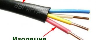
Protective grounding conductors in all electrical installations, as well as neutral protective conductors in electrical installations with voltages up to 1 kV with a solidly grounded neutral, including busbars, must have the letter designation PE and a color designation with alternating longitudinal or transverse stripes of the same width (for busbars from 15 to 100 mm ) yellow and green colors. Zero working (neutral) conductors are designated by the letter N and the color blue. Combined neutral protective and neutral working conductors must have the letter designation PEN and a color designation: blue along the entire length and yellow-green stripes at the ends. Graphic symbols used to indicate conductors on diagrams:
Grounding designation:
Page 2: GOST 12.2.007.0-75. Electrical products. General safety requirements (2137)
- parts of which cannot be under an alternating voltage higher than 42V and under a direct voltage higher than 110V;
— grounding of which is not permitted by the principle of operation or purpose of the product.
3.3.1. (Changed edition, Amendment No. 3).
3.3.2. To connect the grounding conductor, welded or threaded connections must be used.
By agreement with the consumer, the grounding conductor can be connected to the product by soldering or crimping performed by a special tool, device or machine.
3.3.3. Grounding clamps must comply with the requirements of GOST 21130-75.
It is not allowed to use bolts, screws, or studs that act as fasteners for grounding.
pp. 3.2.2-3.3.3. (Modified edition, Change No. 1).
3.3.4. The bolt (screw, stud) for connecting the grounding conductor must be made of metal that is resistant to corrosion, or coated with metal that protects it from corrosion, and the contact part must not have surface coloring.
3.3.4. (Changed edition, Amendment No. 4).
3.3.5. The grounding bolt (screw, stud) must be placed on the product in a place that is safe and convenient for connecting the grounding conductor. Near the place where the grounding conductor, provided for in clause 3.3.2, is to be connected, a grounding sign, applied in any way and not erased during operation, must be placed. The dimensions of the sign and the method of its implementation are in accordance with GOST 21130-75, and for lamps - in accordance with GOST 17677-82.
There must be a contact pad around the bolt (screw, stud) for connecting the grounding conductor. The platform must be protected from corrosion or made of anti-corrosion metal, and not have surface painting.
Measures must be taken against possible loosening of the contacts between the grounding conductor and the grounding bolt (screw, stud) (lock nuts, spring washers).
The diameters of the bolt (screw, stud) and contact pad must be selected according to the current (see Table 1).
Table 1
| Rated current | Nominal thread diameter | diameter of the contact pad of the connection point, mm | |
| electrical product, A | for the connection point, no less | On a surface plane | Elevated relative to the surface |
| St. 4 to 6 | M 3 | 10 | 7 |
| » 6 » 16 | M 3.5 | 11 | 8 |
| » 16 » 40 | M 4 | 12 | 9 |
| » 40 » 63 | M 5 | 14 | 11 |
| » 63 » 100 | M 6 | 16 | 12 |
| » 100 » 250 | M 8 | 20 | 17 |
| » 250 » 630 | M 10 | 25 | 21 |
| » 630 | M 12 | 28 | 24 |
Notes:
1. For currents over 250A, it is allowed to install two bolts instead of one, but with a total cross-section not less than the required one.
When choosing the smallest bolt diameter for consumers and converters of electromagnetic energy, the current value should be taken as the current. consumed by the product from the source (network), for sources of electromagnetic energy - the value of the rated load current.
2. For electromagnetic energy sources having several rated currents, the bolt diameter should be selected based on the largest of these currents.
3.3.5. (Changed edition, Amendment No. 1, No. 3, No. 4).
3.3.6. If the dimensions of the product are small, and also if the grounding bolt (screw) is installed by welding its head, it is allowed to provide the necessary contact surface in connection with the grounding conductor using washers. The material of the washers must meet the same requirements as the material of the grounding bolt (screw, stud).
3.3.6. (Changed edition, Amendment No. 3).
3.3.7. The product must have an electrical connection between all touchable metal non-current-carrying parts of the product that may be energized with grounding elements.
The resistance value between the grounding bolt (screw, pin) and each accessible metal non-current-carrying part of the product, which may be energized, should not exceed 0.1 Ohm.
3.3.8. The following metal non-current-carrying parts of products to be grounded must be equipped with grounding elements:
— shells, cases, cabinets;
- frames, frames, clips, racks, chassis, bases, panels, slabs and other parts of products that may become live if the insulation is damaged.
It is allowed not to provide grounding elements for the following parts of the product (from those listed above):
— housings of products intended for installation on grounded switchboards, metal walls of switchgear chambers, in cabinets;
— non-current-carrying metal parts of the product that have electrical contact with grounded parts, subject to the requirements of clause 3.3.7;
- parts fixed in or passing through insulating material and isolated from both grounded and live parts (provided that during operation of the product they cannot become live or come into contact with grounded parts).
3.3.9. Each part of the product equipped with a grounding element must be designed so that:
- there was the possibility of its independent connection to the grounding electrode or grounding line through a separate branch, so that when any grounded part of the product is removed (for example, for routine repairs), the grounding circuits of other parts are not interrupted;
— there was no need for a series connection of several grounded parts of the product.
3.3.10. Grounding of parts of products installed on moving parts must be done with flexible conductors or sliding contacts.
3.3.11. If there is a metal shell, the element for grounding it must be located inside the shell.
It is possible to perform it outside the shell or to perform several elements both inside and outside the shell.
3.3.11. (Modified edition, Change No. 1).
3.3.12. Electrical contact between the removable and grounded (non-removable) parts of the shell must be achieved by directly pressing the removable part against the non-removable part; at the same time, in places of contact, the surfaces of the removable and non-removable parts of the shell must be protected from corrosion and not covered with electrically insulating layers of varnish, paint or enamel.
It is allowed to electrically connect the removable part of the shell with the non-removable grounded part through the screws or bolts securing it, provided that 1-2 screws or bolts have an anti-corrosion metal coating, and there is no electrically insulating layer of varnish, paint between the heads of these screws or bolts and the removable metal part of the shell, enamel or between them there are serrated washers installed, destroying the electrical insulating layer for or without serrated washers, provided that the removable part is attached to a non-removable grounded one with six or more bolts (or screws) and there is no electrical connection on the removable parts of the electrical devices.
It is also permissible to use toothed washers for the electrical connection of the grounded shell and equipment mounted on the product, and install them for grounding the elements of the product through bolted connections.
3.3.12. (Changed edition, Amendment No. 3).
3.3.13. The requirements listed in clause 3.3 do not apply to products intended for use only in areas with a tropical climate and made in accordance with GOST 15151-69, GOST 9.048-75.
3.4. Requirements for controls
3.4.1. Controls must be provided with inscriptions or symbols indicating the controlled object to which they relate, its purpose and state (“on”, “disabled”, “running”, “brake”, etc.) corresponding to the given position of the control, and (or) providing other information necessary for a particular case.
3.4.2. During automatic operation of the product, buttons for adjustment and manual controls, except for emergency shutdown controls, must be disabled, except in cases dictated by technological necessity.
3.4.3. The use of manual controls and adjustments in a sequence other than the established one should not lead to dangerous situations or should be prevented by introducing a lock.
For products that have several controls for carrying out the same operation from different positions (for example, for remote control and for control directly at the workplace), the possibility of simultaneous control from different positions must be excluded.
Emergency shutdown buttons must be operated without the specified interlock.
3.4.4. In products that have several emergency shutdown buttons, due to the large length or limited visibility, latching buttons must be used, which, after they are pressed, do not return to their original state until they are forced into this state.
It is allowed to use buttons without forced return in case of their impact on power elements, which allow voltage to be applied only after the manual lock has been removed.
3.4.4. (Changed edition, Amendment No. 3).
3.4.5. Controls that are fixed in a set position must be equipped with a pointer (in some cases, a scale) indicating the position and required direction of movement of the control.
3.4.6. Metal shafts of manual drives, handles, handwheels, pedals must be insulated from live parts of the product and have electrical contact with non-removable parts of the product on which the grounding element is located. In this case, the requirement of clause 3.3.7 must be met.
3.4.6. (Changed edition, Amendment No. 1).
3.4.7. The temperature on the surface of controls intended for performing operations without the use of personal protective equipment for hands, as well as for performing operations in emergency situations in all cases, must not exceed 40°C for controls made of metal and 45°C.- for those made of materials with low thermal conductivity.
For equipment where the internal temperature is equal to or below 100°C, the surface temperature should not exceed 35°C. If it is impossible for technical reasons to achieve the specified temperatures, measures must be taken to protect workers from possible overheating.
3.4.8. The control element used to stop (disable) must be made of red material.
The control that is used to start (switch on) must have an achromatic color (black, gray or white). It is allowed to perform this organ in green color.
The control element, which can alternately stop or start the product, must be made only in an achromatic color. The handles of automatic switches may be yellow-brown.
The control that acts to prevent the product from crashing must be yellow.
The control that performs operations other than those listed above must be achromatic or blue.
3.4.9. The emergency shutdown button must be larger in size compared to other buttons.
The “Start” button must be recessed by at least 3mm or have a front ring.
It is allowed to make buttons that are not recessed and without a front ring, that have a free play of at least 4 mm or do not cause dangerous effects when accidentally pressed.
3.4.7-3.4.9. (Changed edition, Amendment No. 3).
3.4.10. The following zones should be used to locate controls intended to be used more than three times during a work shift:
— 1000-1400 mm from the floor level (working platform) when operating the product while standing;
— 600-1000 mm when operating the product while sitting.
3.4.11. The following zones should be used to locate controls intended to be used no more than three times during a work shift:
— 1000-1600 mm from the floor level (working platform) when operating the product while standing;
— 600-1200 mm when operating the product while sitting.
3.4.12. For controls intended for smooth adjustment, it is necessary, when working while standing, to use a zone of 1200-1400 mm from the floor level (working platform), and when working while sitting, 800-1000 mm.
3.4.13. The installation of measuring instruments, the reading of which must be carried out throughout the entire work shift, should be carried out in such a way that the scale of each instrument is at a height from the floor (working platform):
— 1000-1800 mm when working standing;
- 800-1300 mm - when working while sitting.
3.4.14. The installation of measuring instruments for which it is necessary to make accurate readings should be done in such a way that the scale of each instrument is at a height from the floor (working platform):
— 1200-1600 mm when working standing;
- 800-1200 mm - when working while sitting.
The dimensions specified in clauses 3.4.10-3.4.14 may be taken differently depending on the purpose of the product and its operating conditions. In this case, these dimensions must be indicated in the standards or technical specifications for specific types of products.
3.4.10.-3.4.14. (Changed edition, Amendment No. 1).
3.4.15. The pressing force on the handles, handwheels, buttons and pedals should not exceed the values given in the table. 2.
table 2
| Steering effort, daN | |||||
| Switching frequency | lever and rotary | handle and handwheel | button | pedal | |
| handle with fingers | by hand | through fingers | through the palms | ||
| Up to 3 per hour | 5,0 | 35 | 10 | 15 | 30 |
| Sat 3 to 30 per hour | 2,5 | 10 | 5 | 8 | 15 |
| Over 30 per hour | 1,0 | 7 | 4 | 5 | 8 |
Errors in the grounding device
Incorrect PE conductors Sometimes water pipes or heating pipes are used as a grounding conductor, but they cannot be used as a grounding conductor. There may be non-conductive inserts in the plumbing (such as plastic pipes), electrical contact between pipes may be broken due to corrosion, and finally, part of the pipeline may be disassembled for repairs.
Combination of the working zero and the PE conductor Another common violation is the combination of the working zero and the PE conductor beyond the point of their separation (if any) along the energy distribution. Such a violation can lead to the appearance of quite significant currents through the PE conductor (which should not be current-carrying in its normal state), as well as to false trips of the residual current device (if installed).
Incorrect division of the PEN conductor The following method of “creating” a PE conductor is extremely dangerous: the working neutral conductor is determined directly in the socket and a jumper is placed between it and the PE contact of the socket. Thus, the PE conductor of the load connected to this socket is connected to the working zero. The danger of this scheme is that a phase potential will appear on the grounding contact of the socket, and, consequently, on the body of the connected device, if any of the following conditions are met:
- Break (disconnection, burnout, etc.) of the neutral conductor in the area between the socket and the shield (and also further, up to the grounding point of the PEN conductor);
- Rearranging the phase and neutral (phase instead of neutral and vice versa) conductors going to this outlet.
All distribution boards and other types of modular electrical equipment have a grounding sign on the housing. Using this designation, the junction of the main part of the body of the selected electrical equipment with the grounding elements is marked. Thanks to the grounding cable, safety is ensured when using electrical equipment in industrial production.
Electrical products. Grounding clamps and grounding signs. Design and dimensions
current This standard applies to grounding clamps and grounding signs used in electrical products and general purpose devices, explosion-proof and mining products for grounding housings, shells and armor of cables and connecting grounding conductors. The standard does not apply to linear, grounding clamps, clamps of portable grounding devices, grounding clamps used in household products, grounding clamps for products and devices, the requirements for which are regulated by special rules for their manufacture (products and devices of radio engineering, shipbuilding, etc.)
Dimensions of the grounding sign according to GOST 21130-75
The specified GOST specifies not only the dimensions, but also the methods of applying the sign on the equipment of the manufacturer of panels and other electrical equipment. 4 types of designation are regulated:
- Stamping method.
- Casting in steel case.
- Impact method.
- Pressing method in plastic cases.
Clause 3.1 of the above GOST specifies the possibility of making signs using appliqué, paint, or photochemical methods. The only strict requirement is their size:
- When casting or pressing on the body
- When manufactured using the impact method
| D | H | H1 | b | h | r |
| 14 | 8 | 6,0 | 1,2 | 2,5 | 0,6 |
| 18 | 10 | 7,0 | 1,4 | 5,0 | 0,7 |
| 25 | 14 | 9,0 | 1,8 | 5,5 | 0,9 |
Important! The color of the circle of the sign must be noticeably different from the outer surface of the equipment housing. The background is usually painted yellow, and the relief along the contour is made in black or dark gray shades.
If you need to quickly update badges in production, it is best to use stickers that will last 1-2 years, after which they are simply replaced with new ones.
If you are building a new industrial premises and ordering new electrical appliances and equipment, first check for the presence of the “grounded” symbol directly on the housing.
546.2 PEN conductors
546.2.1 In TN systems for permanently installed cables having a cross-sectional area of not less than 10 mm2 for copper or 16 mm2 for aluminum, a single core may be used as a PEN conductor, provided that the part of the installation in question is not protected by residual current devices that react for differential current.
546.2.2 To avoid stray currents, the insulation of a PEN conductor shall be rated for the highest voltage that can be applied to it.
Note - the PEN conductor does not need to be insulated inside complete control and power distribution devices.
546.2.3 In cases where, starting from any installation point, the neutral working and neutral protective conductors are separated, it is prohibited to combine these conductors beyond this point along the flow of energy. At the separation point, it is necessary to provide separate clamps or busbars for the neutral working and protective conductors. The PEN conductor must be connected to a terminal intended for the protective conductor.
