What is a thyristor, its structure and designation on the diagram
A thyristor is a semiconductor element that has only two states: “open” (current flows) and “closed” (no current). Moreover, both states are stable, that is, the transition occurs only under certain conditions. The switching itself occurs very quickly, although not instantly.
In terms of its mode of action, it can be compared to a switch or a key. But the thyristor switches using voltage, and turns off when the current is lost or the load is removed. So the operating principle of a thyristor is not difficult to understand. You can think of it as an electrically controlled key. Well, not really.
A thyristor usually has three outputs. One control and two through which current flows. You can try to briefly describe the principle of operation. When voltage is applied to the control output, the circuit is switched through the anode-collector. That is, it is comparable to a transistor. The only difference is that in a transistor, the amount of current passed depends on the voltage applied to the control terminal. And the thyristor is either completely open or completely closed.
The principle of operation of a thyristor in simple words
Let's consider the principle of operation of a thyristor. The starting state of the element is closed. The “signal” to transition to the “open” state is the appearance of voltage between the anode and the control terminal. There are two ways to return the thyristor to the “closed” state:
- remove the load;
- reduce the current below the holding current (one of the technical characteristics).
In circuits with variable voltage, as a rule, the thyristor is reset according to the second option. Alternating current in a household network has a sinusoidal shape when its value approaches zero and a reset occurs. In circuits powered by DC sources, it is necessary to either forcibly remove the power or remove the load.
After removing the unlocking voltage, the thyristor remains in the open state (the light is on)
That is, the thyristor works differently in circuits with constant and alternating voltage. In a constant voltage circuit, after a short-term voltage appears between the anode and the control terminal, the element goes into the “open” state. Then there can be two scenarios:
- The “open” state is maintained even after the anode-control output voltage has disappeared. This is possible if the voltage applied to the anode control terminal is higher than the non-unlocking voltage (this data is in the technical specifications). The flow of current through the thyristor is stopped, in fact only by breaking the circuit or turning off the power source. Moreover, the shutdown/break of the circuit can be very short-lived. After the circuit is restored, no current flows until voltage is applied to the anode control terminal again.
- After removing the voltage (it is less than the unlocking voltage), the thyristor immediately goes into the “closed” state.
So in DC circuits there are two options for using a thyristor - with and without holding the open state. But more often they use the first type - when it remains open.
If we talk about the internal structure, these are three PNPN junctions
The operating principle of a thyristor in alternating voltage circuits is different. There, the return to the locked state occurs “automatically” - when the current drops below the holding threshold. If the voltage is constantly applied to the anode-cathode, at the output of the thyristor we obtain current pulses that occur at a certain frequency. This is exactly how switching power supplies are built. Using a thyristor, they convert the sine wave into pulses.
The essence of the device
The term “thyristor” comes from the merger of two words: the Greek hýra - door or entrance and the English resistor - resisting. This name was given to a semiconductor device made on the basis of a single crystal of a semiconductor substance and having three or more pn junctions. During operation, this device can have two stable positions:
- closed - corresponding to low conductivity;
- open - offering no resistance to the passage of current.
That is, to paraphrase the definitions, we can say that the thyristor works like a key, by analogy with a door. In one of its states, the lock on the door is open, and people can freely pass through it (electric current), and in the other, it is closed and the door is locked. Therefore, it is often called an electronic switch. In scientific terms, its correct name sounds like a semiconductor with a controlled valve (diode).
The adoption of one of the stable states by an element occurs quickly, but not instantly. To change one to the other, voltage is used. When it is present, the thyristor is in the open state, and when not, it closes. For this, a special additional pin is used. Therefore, the device has three outputs and looks like a transistor. At the same time, their principle of operation is similar, only, unlike a transistor, a thyristor either completely passes the current or prevents its passage.
What is a thyristor and their types
Many have seen thyristors in the “Running Fire” garland; this is the simplest example of the device described and how it works. A silicon rectifier or thyristor is very similar to a transistor. This is a multilayer semiconductor device, the main material of which is silicon, most often in a plastic housing. Due to the fact that its operating principle is very similar to a rectifying diode (AC rectifier devices or dinistors), the designation on the diagrams is often the same - this is considered an analogue of a rectifier.
Photo - Running fire garland diagram
There are:
- ABB turn-off thyristors (GTO),
- standard SEMIKRON,
- powerful avalanche type TL-171,
- optocouplers (say, TO 142-12.5-600 or MTOTO 80 module),
- symmetrical TS-106-10,
- low frequency MTTs,
- triac BTA 16-600B or VT for washing machines,
- frequency TBC,
- foreign TPS 08,
- TYN 208.
But at the same time, IGBT or IGCT type transistors are used for high-voltage devices (furnaces, machine tools, and other industrial automation).
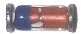
Photo – Thyristor
But, unlike a diode, which is a two-layer (PN) transistor (PNP, NPN), a thyristor consists of four layers (PNPN) and this semiconductor device contains three pn junctions. In this case, diode rectifiers become less efficient. This is well demonstrated by the thyristor control circuit, as well as any electricians’ reference book (for example, in the library you can read a book by the author Zamyatin for free).
A thyristor is a unidirectional AC converter, meaning it conducts current in one direction only, but unlike a diode, the device can be made to operate as an open circuit switch or as a DC rectifying diode. In other words, semiconductor thyristors can only operate in switching mode and cannot be used as amplification devices. The key on the thyristor is not capable of moving to the closed position on its own.
The silicon controlled rectifier is one of several power semiconductor devices, along with triacs, AC diodes, and unijunction transistors, that can switch from one mode to another very quickly. Such a thyristor is called high-speed. Of course, the class of the device plays a big role here.
Characteristics and parameters
A thyristor is a device that simultaneously combines three functions: a rectifier, a switch and an amplifier. The main properties characterizing the device can be presented in the form of the following points:
- A thyristor, like a diode, passes current only in one direction, that is, it works as a rectifier;
- the device switches from one state to another using voltage;
- the amount of current required to switch a thyristor is on the order of several milliamps, while it can pass tens of amperes through itself;
- By changing the time of the applied signal to the control pin, you can regulate the average value of the current flowing through the load, in other words, control the power.
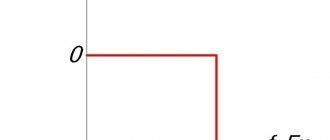
The main function that describes the operation of the device is the current-voltage characteristic (volt-ampere characteristic). It is a flat coordinate system along the Y axis, on which the load current is plotted, and along the X axis, the voltage on the control electrode. Based on the type of nonlinearity of the correspondence between these two quantities, the current-voltage characteristic belongs to the S-type devices.
The characteristic uses letter designations corresponding to key points in the operation of the thyristor. Thus, the coordinate (Vbo; IL) corresponds to the moment of switching on, and the point with coordinates (Vн; Iл) corresponds to the open state. The zone lying on a segment with coordinates (Vbo; IL) and (Vн; In) is considered transitional, that is, unstable.
A thyristor device, in addition to the current-voltage characteristic, is characterized by a number of parameters:
- The highest constant reverse voltage is the value above which a breakdown of the junction occurs.
- Turn-on voltage is the signal value, upon reaching which the element is unlocked.
- Allowable current is the maximum value that a radio device can pass through without changing its characteristics.
- Holding current is the current flowing through the anode and causing the cell to lock.
- Voltage drop - shows the amount of energy that is dissipated by the device (0.5 -1 V).
- Maximum power is determined by the permissible current and the maximum possible voltage applied to the controlled terminals, that is, the nature of the load.
- Turn-off time is the period of time during which the thyristor will completely close. Amounts to microseconds.
- Opening constant control current - indicates the value that is necessary to maintain the device in the open state (anode-cathode). Typically around 100 mA.
We recommend reading: Connecting an electric motor from 380 to 220: diagrams and methods of connecting an electric motor with photos and videos
Specifications
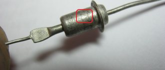
Let's consider the technical parameters of the KU 202e series thyristor. This series presents domestic low-power devices, the main use of which is limited to household appliances: it is used to operate electric furnaces, heaters, etc.
The drawing below shows the pinout and main parts of the thyristor.
Photo - ku 202
- Set reverse on-state voltage (max) 100 V
- Closed voltage 100 V
- Pulse in open position - 30 A
- Repeated pulse in open position 10 A
- Average voltage <=1.5V
- Non-unlocking voltage >=0.2 V
- Set open current <=4 mA
- Reverse current <=4 mA
- Constant type unlocking current <=200 mA
- Set constant voltage <=7 V
- Turn-on time <=10 µs
- Turn-off time <=100 µs
The device turns on within microseconds. If you need to replace the described device, then consult a sales consultant at an electrical store - he will be able to select an analogue according to the diagram.
Photo - thyristor Ku202n
The price of a thyristor depends on its brand and characteristics. We recommend buying domestic devices - they are more durable and affordable. In spontaneous markets you can buy a high-quality, powerful converter for up to a hundred rubles.
Device design
Any thyristor device has at least three terminals: anode, cathode and input. They are produced by various manufacturers and can be in the form of a tablet or a pin. As a rule, the material for their manufacture is silicon. It provides good thermal conductivity and can withstand high power.
Emitter junctions are made using alloy technology, and collector junctions are made using the diffusion method. Planar technology is also used. The concentration of impurities in the emitter regions is much greater than in the base regions. In this case, the thickest layer is the central one. These two factors - thickness and low concentration - allow the device to withstand a fairly large reverse voltage (on the order of hundreds of volts). The anode of the device is connected to the body of the product, which ultimately has a positive effect on heat dissipation.
Asymmetrical thyristors have a slightly different design. In their design, the cathode is connected to the n+ and p zone, and the anode to the p+ and n region. Such connections are called anodic or cathodic short circuits. Their use leads to the appearance of additional resistance between the transitions. This connection reduces transient processes and the lifetime of the main carriers.
The simplest design of a thyristor includes a base connected to a semiconductor crystal and serving as an anode, a cathode terminal, and a control electrode. On top of the crystal is covered with an insulator and a lid, which helps protect the device from mechanical damage and at the same time serves as a heat sink.
Purpose of the device
Thyristors are semiconductor devices with three (or more) pn junctions intended for use as electronic switches in electrical current switching circuits. They switch electrical circuits, regulate voltage, and convert direct current into alternating current.
In design and principle of operation, it is very similar to a semiconductor diode, but unlike it, the thyristor is controlled. The “key” nature of the action of the trinistor allows it to be used for switching electrical circuits where previously only electromagnetic relays served for this purpose.
Semiconductor switches are lighter, more compact and many times more reliable in operation than electromagnetic relays with mechanically closed contacts. Unlike such relays, they switch at a very high speed - hundreds and thousands of times per second, and if necessary - even faster. SCRs are used in modern electrical communication equipment, in high-speed remote control systems, in computers and in energy devices.
Types of thyristors
Lockable ones were discussed above, but there are many more types of semiconductor thyristors that are also worth mentioning. Certain types of thyristors are used in a variety of designs (chargers, switches, power regulators). Somewhere it is required that control be carried out by supplying a stream of light, which means an optothyristor is used. Its peculiarity is that the control circuit uses a semiconductor crystal that is sensitive to light. The parameters of thyristors are different, they all have their own characteristics that are characteristic only of them. Therefore, you need to at least have a general idea of what types of these semiconductors exist and where they can be used. So, here is the entire list and the main features of each type:
- Thyristor diode. The equivalent of this element is a thyristor, to which a semiconductor diode is connected back-to-back.
- Dinistor (diode thyristor). It can go into full conduction if a certain voltage level is exceeded.
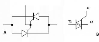
- Triac (symmetrical thyristor). Its equivalent is two thyristors connected back-to-back.
- The high-speed inverter thyristor has a high switching speed (5... 50 μs).
- Thyristors with field effect transistor control. You can often find designs based on MOS transistors.
- Optical thyristors that are controlled by light flows.
Thyristor protection
Thyristors are devices critical to the rate of rise of forward current diA/dt and forward voltage duAC/dt. Thyristors, like diodes, are characterized by the flow of reverse recovery current, a sharp drop of which to zero aggravates the possibility of overvoltages with a high duAC/dt value. Such overvoltages are a consequence of a sudden cessation of current in the inductive elements of the circuit, including small installation inductances. Therefore, to protect thyristors, various CFTP circuits are usually used, which in dynamic modes protect against unacceptable values of diA/dt and duAC/dt.
In most cases, the internal inductive reactance of the voltage sources included in the circuit of the switched-on thyristor turns out to be sufficient so as not to introduce additional inductance LS. Therefore, in practice, there is often a need for CFTPs that reduce the level and speed of overvoltages during shutdown (Fig. 7).
Rice. 7. Typical thyristor protection circuit
For this purpose, RC circuits connected in parallel with the thyristor are usually used. There are various circuit modifications of RC circuits and methods for calculating their parameters for different conditions of using thyristors.
For turn-off thyristors, switching trajectory formation circuits are used, similar in circuit design to CFTP transistors.
Source: School for Electrician
9894
Bookmarks
Comment 2
Latest publications
Igor Makovsky and Alexey Smirnov discussed issues of reliability of energy supply in the Kursk region
Yesterday, at 16:24 36
Igor Makovsky: uninterrupted power supply to consumers is our contribution to achieving national goals
March 3 at 21:51 36
In 2022, Kurskenergo energy workers installed more than 15,000 anti-magnetic seals
March 3 at 11:30 44
National Research University "MPEI" signed a cooperation agreement with the Rosatom Technical Academy
March 1 at 15:07 47
Rosseti Siberia informs residents of the Novokuznetsk region about changes in the power grid maintenance scheme
March 1 at 08:05 62
Igor Makovsky: power engineers provide comprehensive support to people in need of help
February 28 at 20:46 52
How to expand the market for regional medical equipment manufacturers?
February 28 at 19:33 47
Reliable power supply for electrical substation equipment in Vladimir is guaranteed
February 28 at 17:58 64
Choosing the type of heating for a cottage village: central boiler room
February 28 at 15:16 54
The Kalugaenergo branch provided socially significant facilities in the Kozelsky district with street lighting
February 25 at 12:08 108
Comments 2
Oleg
A very convenient selection of materials for an essay on FOE. Thank you very much
June 21, 2014 at 16:11
Bookmarks
Principle of operation
Thyristors are essentially switching devices. The structure of a simple element consists of npnp layers and has three transitions. Two of them work in the forward direction, and one in the reverse direction. The device has two outer regions called anode (p) and cathode (n). To understand the principle of operation of a thyristor, it can be represented as dual transistors: npn and pnp. In this case, the middle zone of the second transistor (n) is connected to the outer zone of the first.
We recommend reading: How to measure resistance with a multimeter: instructions, photos, videos
As a result, it turns out that the outer zones will be emitter junctions, and the middle zones will be collector junctions. The base area of the first element will coincide with the collector of the second and vice versa. Based on this, the collector current of the transistors will also be the base current.
The physical processes occurring in the element can be described as follows. If there was only one junction in the device, only a reverse current would arise, caused by minority charge carriers. If a direct voltage is applied to the emitter junction, the collector current will increase and the voltage across it will decrease. In a transistor, to switch it to saturation mode (maximum throughput), a direct voltage is applied to the emitter, and between the base and collector it is reduced to single values.
Same thing in a thyristor. Minority charges are injected through the junctions of the anode and cathode, leading to a decrease in the resistance of the control electrode. When direct voltage is applied, that is, a negative potential is applied to the cathode, and a positive potential is applied to the anode, a small current begins to flow through the device. This state corresponds to the closed position.
An increase in voltage leads to the injection of carriers into the controlled junction. As a result, on the one hand, its resistance increases due to depletion of the majority carriers, since the junction turns on in the opposite direction, and on the other hand, it increases due to the entry of new charges into its region.
When the voltage reaches a certain value, these two phenomena are balanced, and even an increase in voltage by a small amount leads to an avalanche-like process of unlocking the thyristor. This state resembles the saturation mode of a transistor. The junction resistance becomes minimal, and the current value is determined by the load resistance.
Thyristor operating modes
The thyristor has three operating modes:
- Forward lock
- Reverse blocking
- Forward conduction
Forward lock
In this state or mode, forward conduction of current is blocked. The top diode and bottom diode are forward biased and the junction in the center is reverse biased. Thus, the thyristor does not turn on because the gate does not fire and no current flows through it.
Reverse blocking
In this mode, the connection between the anode and cathode is reversed and no current flows through it. Thyristors can only conduct current in one direction and it blocks in the opposite direction, so the flow of current is blocked.
Forward conduction
When current is applied to the gate, the thyristor is triggered and it begins to conduct current. It remains on until the forward current drops below a threshold, and this can be achieved by turning off the circuit.
DC circuit
In a direct current circuit, a thyristor operates on the principle of delivering a pulse of positive polarity, of course, relative to the cathode. The duration of the transition from one state to another is greatly influenced by a number of characteristics. Namely:
- Type of load (inductive, active, etc.).
- The rate of rise of the pulse and its amplitude, meaning the load current.
- The magnitude of the current load itself.
- Voltage in the circuit.
- The temperature of the device itself.
The most important thing here is that there is no sudden increase in voltage in the network where this device is installed. In this case, the thyristor may turn on spontaneously, and the control signal will be absent at this time
AC circuit
In this network, the thyristor switch works a little differently. This device makes it possible to perform several types of operations. Eg:
- Switching on and off a circuit in which an active or active-reactive load acts.
- You can change the value of the effective load and its average value due to the ability to change (adjust) the supply of the control signal itself.
Thyristor in an alternating current circuit.
But keep in mind that a thyristor switch can only pass a signal in one direction. Therefore, the thyristors themselves are installed in the circuit, so to speak, in an anti-parallel connection.
Two-transistor analogy of a thyristor
The collector current from the NPN transistor is supplied directly to the base of the PNP transistor and the collector current of the PNP transistor is supplied to the base of the NPN transistor. These connected transistors rely on each other for conduction.
Thus, a base current is required to conduct one of the transistors. When the anode terminal of the thyristor is negative with respect to the cathode, the NP junction becomes forward biased and the PN junction becomes reverse biased.
We recommend reading: Types of resistors, what they are needed for, how to check, designation, connection
Two transistor analogues of a thyristor
Here the reverse current flow is blocked until the breakdown voltage is applied. After the breakdown voltage, it begins to conduct without a gate signal being applied. This is one of the negative characteristics of thyristors, since it triggers conduction when the voltage is reversed.
When the anode terminal is made positive with respect to the cathode, the outer junctions are forward biased and the central NP junction is reverse biased and blocks forward current. Thus, to induce it into conduction, a positive current is applied to the base of the transistors.
The two transistors are connected in a regenerative circuit and this causes the transistor to conduct saturation. Thus, we can say that thyristors block current both in the direction of the AC source in the off state, and can be turned on by applying a positive current to the base of the transistor.
Thyristor check
Before you buy a device, you need to know how to test a thyristor with a multimeter. The measuring device can only be connected to a so-called tester. The diagram by which such a device can be assembled is presented below:
Photo - thyristor tester
According to the description, it is necessary to apply a positive voltage to the anode, and a negative voltage to the cathode. It is very important to use a value that matches the resolution of the thyristor. The drawing shows resistors with a nominal voltage of 9 to 12 volts, which means that the tester voltage is slightly higher than the thyristor. After you have assembled the device, you can begin to check the rectifier. You need to press the button that sends pulse signals to turn it on.
Testing the thyristor is very simple; a button briefly sends an opening signal (positive relative to the cathode) to the control electrode. After this, if the running lights on the thyristor come on, the device is considered inoperative, but powerful devices do not always react immediately after the load arrives.
Photo - circuit tester for thyristors
In addition to checking the device, it is also recommended to use special controllers or a control unit for thyristors and triacs OWEN BOOST or other brands; it works approximately the same as a power regulator on a thyristor. The main difference is a wider range of voltages.
Video: operating principle of a thyristor
Classification characteristics
According to the control method, the following types of thyristors are distinguished:
Diode (dinistors)
They are activated by a high voltage pulse applied to the anode and cathode. The design contains 2 electrodes, without a control one.
Triode (sCR)
They are divided into two groups. In the first, the control voltage is supplied to the cathode and the control electrode, in the second - to the anode and the control electrode.
Triacs
Perform the functions of two thyristors connected in parallel.
Optothyristors
Their functioning is carried out under the influence of light flux. The function of the control electrode is performed by a photocell.
According to reverse conductivity, thyristors are divided into:
- reverse conductive;
- reverse non-conductive;
- with non-standardized reverse voltage value;
- passing currents in two directions.
Specific methods of thyristor control
- Amplitude.
It represents the supply of a positive voltage of varying magnitude to the Ue. The opening of the thyristor occurs when the voltage value is sufficient to break through the control transition of the rectifying current (Irect). By changing the voltage on the UE, it becomes possible to change the opening time of the thyristor.
The main disadvantage of this method is the strong influence of the temperature factor. In addition, each type of thyristor will require a different type of resistor. This point does not add ease of use. In addition, the opening time of the thyristor can be adjusted only while the first 1/2 of the positive half-cycle of the network lasts.
- Phase.
It consists of changing the phase Ucontrol (in relation to the voltage at the anode). In this case, a phase shift bridge is used. The main disadvantage is the low slope of Ucontrol, so it is possible to stabilize the opening moment of the thyristor only for a short time.
- Pulse-phase.
Designed to overcome the shortcomings of the phase method. For this purpose, a voltage pulse with a steep edge is applied to Ue. This approach is currently the most common.
Application of thyristor
The purpose of thyristors can be very different, for example, a homemade welding inverter using thyristors, a charger for a car (thyristor in the power supply) and even a generator are very popular. Due to the fact that the device itself can pass both low-frequency and high-frequency loads, it can also be used for a transformer for welding machines (their bridge uses exactly these parts). To control the operation of the part in this case, a voltage regulator on the thyristor is needed.
Photo - using Thyristor instead of LATR
Don't forget about the ignition thyristor for motorcycles.