Not a single electrical network is immune from voltage surges; there are many reasons that cause this phenomenon, ranging from overload to phase imbalance. Such throws can damage household appliances, which is why almost all modern electronic devices have protection. If, after the next surge in the power supply of any device, a fuse has burned out, after replacing it, do not rush to turn on the equipment. Just in case, check the varistor for serviceability with a tester or multimeter.
Before proceeding to testing, we recommend that you familiarize yourself with a brief description of the varistor, its operating features and characteristics. This information may be useful when searching for an analogue to replace a failed element.
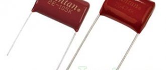
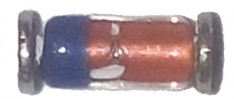
Appearance of varistors
What is a varistor
A varistor is a variable resistor made of semiconductor material that is capable of changing its electrical resistance depending on the voltage applied to it.
The operating principle of such an electronic component differs from a conventional resistor and potentiometer. A standard resistor has a constant resistance value at any time, regardless of the voltage in the circuit; a potentiometer allows you to change the resistance manually by turning the control knob. But the varistor has a nonlinear symmetrical current-voltage characteristic and its resistance completely depends on the voltage in the circuit.
Thanks to this property, varistors are widely and effectively used to protect electrical networks, machines and equipment, as well as radio-electronic components, boards and microcircuits, regardless of the type of voltage. They have a low manufacturing price, are reliable in use and can withstand high loads.
Varistors are used both in high-voltage installations up to 20 kV, and in low-voltage installations from 3 to 200 V as a voltage limiter. Moreover, they can operate both in networks with alternating and direct current. They are used to regulate and stabilize current and voltage, as well as in overvoltage protective devices. They are used in the design of surge protectors, power supplies, mobile phones, SPDs and other SPS.
Application of varistor
Varistors are used in most consumer electronics around the world. They can be found in almost any electronics. They are also found in automotive electronics, cellular and household appliances, network filters and computer hardware. By the way, a good power supply differs from a Chinese one in that the former has a varistor. Therefore, a good power supply is much more durable and repairable.
Varistor in the power supply
Craftsmen also use varistors when assembling their fakes from LED lamps. And special craftsmen manage to place them in sockets and plugs. You can think of a lot to protect your electronics if you have a problem with power surges in your home. The scope of their application is extensive. These can be installations with a voltage of 20 kV and with a voltage of 3V. This may be a network with alternating current, or it may be with direct current. Truly, varistors can be found almost everywhere.
So what characteristics does a varistor have?
As a rule, the following parameters are used to describe a varistor:
Varistor capacitance in closed state. During operation, its value may change. At particularly high current, it decreases to almost zero. Denoted as Co.
The maximum energy in Joules that a varistor can absorb in one pulse. Indicated by W. Maximum value of pulse current, at 8/20ms. Designated as Ipp. The root mean square value of the alternating voltage in the circuit. Denoted as Um. Limit voltage at direct current. Denoted as Um=. For approximate calculations of operating voltage, we recommend using an Un value of no more than 0.6 with alternating current and 0.8 with direct current.
In 220V networks, varistors with a minimum classification voltage (Un) from 380 to 430 V are used. We should not forget about the varistor capacity when selecting. As a rule, it depends on the size of the varistor. Thus, the varistor TVR 20 431 has a capacity of 900 pF, and TVR 05 431 - 80 pF. These values can always be found in the reference material.
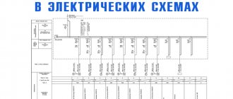
In the diagrams, the varistor is designated as follows:
RU is the designation of the varistor itself. The number next to RU is the sequential number. That is, what number of varistors are they in the circuit? The letter U at the bottom left of the oblique passing through the varistor means that this element has the ability to change voltage. Also, the varistor markings are often indicated on the diagrams. We will talk about marking and its decoding below.
This is how a varistor is designated in diagrams
Varistor properties
The main property of a varistor is its ability to reduce its own resistance depending on the voltage supplied to it. The higher the voltage is applied, the less resistance it begins to have. Varistors are connected to the electrical board in parallel with the protected device; in normal mode, the varistor operates at the rated voltage of the device it protects.
In normal mode, the electricity passing through the varistor is negligible, and therefore in such conditions it acts as an insulator.
If a sharp surge in electricity occurs, the varistor, due to its nonlinear characteristics, instantly reduces the value of its resistance to tenths of an ohm and removes the load from the general network, protecting it by radiating the excess energy received with heat. In such situations, a voltage of thousands of amperes can instantly pass through the varistor.
A varistor is a completely inertia-free device; as soon as the voltage in the network increases, its resistance immediately drops.
Varistor selection
To effectively and reliably protect your equipment, you need to choose a varistor wisely. As a rule, to protect household appliances, varistors with a threshold voltage value from 275 to 430 V are used. We will not go into particular detail in the selection of varistors taking into account other values (capacitance, etc.). There are many nuances here that simply cannot be considered in the format of this article. For a more accurate selection of a varistor, we can recommend using reference books on varistors. They indicate all the characteristics that a particular varistor has. This will allow you to choose the most suitable one for your goals and objectives.
Another important parameter when choosing a varistor is the response speed. As a rule, for most varistors it is about 25 ns. But this is not always enough.
Then varistors with shorter response times are suitable for you. An unattainable ideal in terms of response speed are varistors manufactured using the SIOV-CN multilayer structure technology. Their response speed can be less than 1 ns.
Such varistors are necessary for protection against static electricity. In household appliances, such varistors are practically not used.
A varistor set to zero can serve as a guarantee of the life of your equipment during any power surges. Naturally, taking into account the fact that it is installed on the phase too.
Have you probably heard about cases when many people’s electronics burned out at once? This happens precisely due to the fact that only the phase goes through the wires. A varistor also protects against this.
Types of varistors
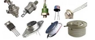
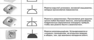
In appearance there are:
- film;
- in the form of tablets;
- core;
- disk.
Rod ones can be equipped with a moving contact. They will look like their name. In addition, there are low voltage, 3-200 V and high voltage 20 kV. For the former, the current fluctuates between 0.0001-1 A. This does not affect the designation according to the diagram in any way. In radio equipment, of course, low voltage is used.
To check the performance of the varistor, you need to pay attention to the appearance. It can be found at the input of the circuit (where power is supplied). Since a very large current passes through it - compared to the protected circuit - this, as a rule, affects its body (chips, burnt areas, darkening of the varnish coating). And also on the board itself: at the soldering site, the wiring tracks may peel off, causing the board to darken. In this case, it must be replaced.
However, even if there are no visible signs, the varistor may be faulty. To check its serviceability we will have to unsolder one of its pins, otherwise we will check the circuit itself. For continuity testing, a multimeter is usually used (although you can, of course, try a megger, you just need to take into account the voltage it creates so as not to burn the varistor). It is not difficult to ring it; it is connected to the contacts and its resistance is measured. We set the tester to the highest possible limit and make sure that the value is at least several hundred megohms, provided that the multimeter voltage does not exceed the response voltage of the varistor.
However, an infinitely large resistance, provided that the ohmmeter is quite powerful (if I can use this word), this also indicates a malfunction. When checking a semiconductor, it is necessary to remember that it is still a conductor and it must show resistance, otherwise we have a completely burnt part.
Varistor capacity
Since the varistor behaves like a dielectric when connected to both power contacts, at normal voltage it acts more like a capacitor rather than a resistor. Each semiconductor varistor has a certain capacitance, which is directly proportional to its area and inversely proportional to its thickness.
When used in DC circuits, the capacitance of a varistor remains more or less constant provided that the applied voltage is not greater than the rated voltage, and its capacitance decreases sharply when the rated voltage is exceeded. As for AC circuits, its capacitance can affect the stability of the devices.
Operating principle of varistors
In its normal state, a varistor has a very high resistance (according to various sources, from hundreds of millions of Ohms to billions of Ohms). It passes almost no current through itself. As soon as the voltage exceeds the permissible value, the device loses its resistance thousands, or even millions, of times. After the voltage normalizes, its resistance is restored. If a varistor is connected in parallel with an electrical appliance, then during a voltage surge the entire load will fall on it, and the devices will remain safe.
The principle of operation of a varistor, if explained in simple terms, boils down to the following. When there is a surge in the electrical network, it acts as a valve, passing through itself an electric current in such a volume as to reduce the potential to the required level. After the voltage has stabilized, this “valve” closes and our electrical circuit continues to operate as normal. This is the purpose of a varistor.
The principle of operation of a varistor
The resistance of a varistor depends on the voltage supplied to it. As a rule, up to the threshold value, the resistance of the varistor is high (more than 1-2 megaohms). When the voltage threshold is passed, the resistance of the varistor rapidly decreases. This feature of the varistor is excellent in protecting electronics from high voltage surges. After all, the pulse current in this case goes through the varistor and is dissipated in the form of heat. However, if the threshold voltage value is maintained for a long time, the varistor overheats and “burns out”.
“Burns” in quotes, since the varistor often explodes. Or it shorts out, and then ignition may occur. For this purpose, a fuse is placed in front of the varistor.
By the way, when replacing a fuse, we recommend checking the varistor at the same time. It is very common for a fuse to fail due to a dead varistor. If you don't do this, at the next power surge you risk more than the varistor and fuse.
To avoid fires, thermistors began to be soldered into varistors. The thermistor absorbs excess thermal energy, which further protects your equipment from combustion. Such varistors are sold immediately assembled.
Marking, main characteristics and parameters
Each varistor manufacturer labels its product in a certain way, so there are quite a large number of designation options and their interpretations. The most common Russian varistor is K275, and popular foreign-made components are 7n471k, kl472m and others.
We recommend reading: Three-position switch: biscuit, zero position, packet and latching
The designation of the CNR-10d751k varistor can be deciphered as follows: CNR – metal oxide varistor; d – means that the component is disk-shaped; 10 is the diameter of the disk; 751 – response voltage for this device (calculation is done by multiplying the first two digits by 10 to the power equal to the third digit, that is, 75 multiplied by 10 to the first power, you get 750 V); k is the permissible deviation of the rated voltage, which is equal to 10% in any direction (l – 15%, M – 20%, P – 25%).
The main characteristics of varistors are the following parameters:
Classification voltage is the voltage at certain values of current flowing through the varistor (usually this value is 1 mA). This parameter is conditional and does not affect the device selection;
The maximum permissible voltage is the voltage range (rms or rms value) at which the varistor begins to reduce its resistance;
Maximum absorption energy is a characteristic showing the value of energy that the varistor dissipates and does not fail when exposed to a single pulse (measured in Joules);
Maximum pulse current – normalizes the rise time and duration of the current pulse (measured in Amperes);
Capacitance is a very important parameter, which is measured when the varistor is closed and at a given frequency (drops to zero if a large current is applied to the varistor);
Permissible deviation - deviation from the nominal potential difference in both directions (indicated as a percentage).
Response time is the period of time during which the varistor transitions from a closed state to an open state (usually several tens of nanoseconds).
Lesson 1. Purpose and principle of operation of surge arresters
Nonlinear surge suppressors (OSN) are electrical devices designed to protect equipment of power supply systems from switching and lightning surges. The main element of the surge arrester is a nonlinear resistor - varistor (varistor, from the English Vari(able) (Resi)stor - variable, changing resistance).
The main difference between the material of nonlinear resistors of limiters and the material of resistors of valve-type arresters is a sharply nonlinear current-voltage characteristic (volt-ampere characteristic) and increased throughput. The use of highly nonlinear resistors in surge arresters has made it possible to eliminate spark gaps from the design of the device, which eliminates a number of disadvantages inherent in valve-type arresters.
The main component of the material of surge arrester resistors is zinc oxide (oxide) ZnO. Zinc oxide is mixed with oxides of other metals - oxide and cobalt oxide, bismuth oxide, etc. The manufacturing technology of zinc oxide resistors is very complex and labor-intensive and is close to the requirements for the production of semiconductors - the use of chemically pure starting material, compliance with cleanliness requirements, etc. The main operations in manufacturing are mixing and grinding the components, molding (pressing) and firing. The microstructure of varistors includes zinc oxide crystals (n-type semiconductor) and an intercrystalline layer (p-type semiconductor). Thus, varistors based on zinc oxide ZnO are a system of series-parallel connected p-n junctions. These p–n junctions determine the nonlinear properties of varistors, that is, the nonlinear dependence of the amount of current flowing through the varistor on the voltage applied to it.
Currently, varistors for limiters are manufactured as cylindrical disks with a diameter of 28–150 mm and a height of 5–60 mm (Fig. 1). Aluminum electrodes with a thickness of 0.05-0.30 mm are applied to the end part of the disks using metallization. The side surfaces of the disk are coated with glypthal enamel, which increases the throughput of current pulses with a steep front.
Rice. 1. Nonlinear resistor - varistor
The diameter of the varistor (more precisely, the cross-sectional area) determines the current carrying capacity of the varistor, and its height determines the voltage parameters.
When manufacturing surge arresters, one or another number of varistors are connected in series in a so-called column. Depending on the required characteristics of the arrester and its design and the varistors available at the enterprise, the limiter can consist of one column (consisting even of one varistor) or a number of columns connected to each other in series/parallel.
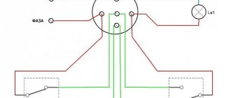
To protect electrical equipment from lightning or switching overvoltages, the surge arrester is connected in parallel with the equipment (Fig. 2).
Fig.2
The protective properties of the surge arrester are explained by the current-voltage characteristic of the varistor.
The volt-ampere characteristic of a particular varistor depends on many factors, including manufacturing technology, type of voltage - direct or alternating, frequency of alternating voltage, parameters of current pulses, temperature, etc.
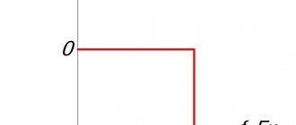
A typical current-voltage characteristic of a varistor with the highest long-term permissible voltage of 0.4 kV on a linear scale is shown in Fig. 3.
Rice. 3. Volt-ampere characteristic of the varistor
On the volt-ampere characteristic of the varistor, three characteristic sections can be distinguished: 1) the region of low currents; 2) medium currents and 3) high currents. The low current region is the operation of a varistor under an operating voltage that does not exceed the maximum permissible operating voltage. In this area, the resistance of the varistor is very significant. Due to the imperfection of the varistor, the resistance, although high, is not infinite. therefore, a current flows through the varistor, called conduction current. This current is small - tenths of a milliammeter.
When lightning or switching overvoltage pulses occur in the network, the varistor switches to medium current mode. At the boundary of the first and second regions, the volt-ampere characteristic bends, and the resistance of the varistor sharply decreases (to fractions of an Ohm). A current pulse briefly flows through the varistor, which can reach tens of thousands of amperes. The varistor absorbs the energy of the overvoltage pulse, then releasing it in the form of heat, dissipating it into the surrounding space. The network overvoltage pulse is “cut off” (Fig. 4).
Rice. 4
In the third region (high currents), the varistor resistance increases sharply again. This area is emergency for the varistor.
Advantages and disadvantages of varistors
Important advantages of a nonlinear resistor (varistor) are its stable and reliable operation with high frequencies and heavy loads. It is used in many devices operating with voltages from 3 V to 20 kV, is relatively simple and cheap to produce and is effective in operation. Additional important benefits are:
- high response speed (nanoseconds);
- long service life;
- ability to monitor voltage drops (inertia-free method).
Despite the fact that this electronic component has many advantages, it also has disadvantages that affect its use in various systems. These include:
- low-frequency noise during operation;
- component aging (loss of parameters over time);
- high capacity: depends on the voltage and type of element, ranges from 70 to 3200 pF and affects the performance of the device;
- at maximum voltage values, power is not dissipated - it overheats significantly and fails at prolonged maximum voltage values.
Varistor protection of equipment
Varistor protection is used in household appliances. They can be soldered into the board itself, or brought out and secured with separate wires. Varistors must be connected in parallel. Connecting them in series simply does not make sense. In this case, current simply will not flow through the circuit.
How does varistor protection work?
For example, lightning struck near your house. Or she could have gotten caught in a power line. There is a power surge in the network. The varistor absorbs it and if the pulse is too strong/long, the varistor dies. That is, a varistor guarantees that your sensitive electronics will not burn out from a power surge. However, it should be remembered that the varistor can become a short circuit point during prolonged operation at maximum voltage.
Above we described several ways to avoid this. Use varistors with thermistors or include fuses in the circuit. To simplify everything as much as possible: at low voltage a varistor is a blocking device, at high voltage it is a conductive device.
Diagnostics
To test this electronic device, special equipment called a tester is used. So, to carry out the test you will need a varistor, the principle of which is to change the resistance parameters, and a testing device. Before you start, you need to turn on the device and switch to resistance mode. Only then will the device meet all the necessary technical requirements, and the amount of resistance will be enormous.
Before starting testing, it is necessary to check the technical condition of the device. First of all, you should look at its appearance. The device should not show any cracks or signs that it has burned out. You should not inspect the device negligently, as any minor breakdown can lead to unpleasant circumstances.
Operating principle
A varistor is a semiconductor device with a symmetrical nonlinear current-voltage characteristic. Based on its shape, we can conclude that the varistor operates in both alternating and direct current. Let's look at it in more detail.
In normal condition, the current through the varistor is extremely small; it is called leakage current. It can be considered as a dielectric component with a certain electrical capacitance and can be said to not allow current to pass through. But, at a certain voltage (in the picture it is + - 60 Volts) it begins to pass current.
In other words, the principle of operation of a varistor in protective circuits resembles a spark gap, only an arc discharge does not occur in a semiconductor device, but its internal resistance changes. As the resistance decreases, the current increases from a few microamps to hundreds or thousands of amperes.
Conventional graphical representation of a varistor in diagrams:
The designation of the element on the diagrams resembles a regular resistor, but crossed out diagonally by a line on which the letter U can be printed. To find this element on the board or in the circuit, pay attention to the labels; most often they are designated as RU or VA.
Read also: How to sharpen a Gillette razor blade
Varistor appearance:
A varistor is installed in parallel with the circuit to protect it. Therefore, when the voltage pulse of the protected circuit occurs, the energy does not enter the device, but is dissipated in the form of heat on the varistor. If the pulse energy is too high, the varistor will burn out. But the concept will burn out, there are two options for development. Either the varistor will simply break into pieces, or its crystal will be destroyed and the electrodes will be short-circuited. This will cause the tracks and conductors to burn out, or the housing elements and other parts will catch fire.
To avoid this, a fuse is installed in front of the varistor in series with the entire circuit on the signal or supply wire. Then, in the event of a strong voltage pulse and long-term operation or burnout of the varistor, the fuse will also burn, breaking the circuit.
In short, what is such a component for? Its properties make it possible to protect the electrical circuit from harmful surges of voltage that can occur both on information lines and on electrical lines, for example, when switching powerful electrical appliances. We will discuss this issue a little below.
Varistor selection
To choose the right varistor for a particular device, you need to know the characteristics of its power source: resistance and transient pulse power. The maximum permissible current value is determined, among other things, by the duration of its influence and the number of repetitions, therefore, if you install a varistor with a low peak current value, it will quickly fail. In short, to effectively protect the device it is necessary to choose a varistor with a voltage that has a small margin to the rated one.
Also, for the trouble-free operation of such an electronic component, the rate of dissipation of absorbed thermal energy and the ability to quickly return to a state of normal operation are very important.
Main settings
To choose the right varistor, you need to know its main technical characteristics:
- The classification voltage may be designated as Un. This is the voltage at which a current of 1 mA begins to flow through the varistor; with further excess, the current increases like an avalanche. It is this parameter that is indicated in the marking of the varistor.
- Rated power dissipation P. Determines how much the element can dissipate while maintaining its characteristics.
- The maximum energy of a single pulse W. Measured in Joules.
- Maximum pulse current Ipp. Despite the fact that the front rises within 8 μs, and its total duration is 20 μs.
- Container in closed state - Co. Since in the closed state a varistor is like a capacitor, because its electrodes are separated by a non-conducting material, it has a certain capacitance. This is important when the device is used in high-frequency circuits.
There are also two types of stress:
— maximum effective or root mean square variable;
- Um= — maximum constant.
How to check a varistor with a multimeter?
Checking a varistor using a tester or multimeter is a useful skill for radio amateurs and people who are handy and like to repair broken equipment themselves. This will be discussed in this article. What a varistor is intended for and what it does is described in sufficient detail in this article - an article about a varistor.
But let’s remember a little: a varistor is designed to protect variable or permanent circuits from overvoltage. It stands parallel to the circuit being protected and normally has a high resistance.
When the threshold voltage is reached, which depends on the brand of the varistor, its resistance decreases from very high to very small. A varistor absorbs this overvoltage and dissipates it into the atmosphere as heat.
Thus, it removes excess energy from the circuit, thereby protecting the circuit from failure.
Now let's start checking. Before using the tester, carefully inspect the radio element. It may have signs of burning, chips, or even break down.
We recommend reading: DIY FM antenna for a music center
A careful inspection will save you from unnecessary work, although checking with a device does not take much effort, but still.
A varistor can also lose its properties over time, from external conditions and during the aging process - this is also worth paying attention to.
Measurements with a dial gauge
Such a device is considered analog. Its design uses an electromechanical head. It is a frame placed in a magnetic field. Depending on the current strength, the arrow in the frame deviates, stopping in a certain position. The range of needle deflection is graduated by numbers, according to which the resistance is calculated.
Before you start checking the varistor, you will need to set up the dial multimeter. To do this, it is calibrated. Its essence comes down to setting the zero position of the arrow by rotating a special handle while connecting the probes to each other.
To do this, the switch button selects the operating mode corresponding to the “Ω” icon, and the slide switch is set to the highest limit of resistance measurement by the tester. Most often it is designated as “x100”, which corresponds to megaohms. The resistance is measured from the power source (battery) installed in the device. Therefore, if you cannot set the needle to zero, the battery will need to be replaced.
When carrying out direct measurements, touch one terminal of the varistor with one probe of the tester, and touch the other with the other. As a result, three outcomes are possible:
- The arrow will deflect to zero or show resistance in the kilo-ohm region. A conclusion is made that the element is faulty (breakdown).
- The measurement result is within hundreds of megaohms. This reading indicates the serviceability of the varistor.
- When you touch the terminals of the radio element, the arrow does not react in any way. Possible reasons are as follows: the operating range of the device is not enough to measure the resistance value of the varistor, the device is faulty, the radio element is faulty (break).
Digital tester
Using a digital multimeter, checking the varistor for functionality will be a little easier than using an analog one. This is due to the fact that the digital tester has an LCD display in its design, which clearly displays the measured resistance.
The operation of this type of tester is based on an analog-to-digital converter, the operating principle of which is based on comparing the measured signal with a reference one. It should be noted that if, when you turn on the tester, a flashing battery icon appears on the screen, the battery will need to be replaced. The procedure for measuring the resistance of a varistor can be represented as follows:
The switch sets the maximum resistance measurement limit. Typically this limit is indicated by a number and a letter. If just numbers are written, then the unit of measurement is Ohm, the letter K after the number means kilo-ohm, the letter M means mega-ohm.
- The probes are fixed on two terminals of the varistor, and the reverse ends of the wires with plugs are inserted into the tester sockets marked Ω and COM. Since the polarity of the signal applied to the varistor does not matter, it does not matter which wire is connected to which terminal of the element. Although it is customary that a black cord is inserted into the COM connector.
- The device is turned on by pressing the ON/OFF button on the tester.
- If a unit is displayed on the indicator, this means that a small measurement limit has been selected.
- If numbers other than one are displayed on the screen, then this is the value of the measured resistance.
When interpreting the measurement result, the tolerance should also be taken into account. Each radio element has its own tolerance indicator. For example, if the tolerance is 10 percent and the internal resistance of the varistor is specified as 100 MΩ, then the results obtained should be between 90 and 110 MΩ. If the measured resistance of an element is found to be below or above this range, then it can be considered faulty.
Now that we have the basics covered, we can move on to checking the varistor
Determining the functionality of the element (step-by-step instructions)
For this operation we will need the following tools:
- Screwdriver (usually Phillips). To get to the power supply board, you will need to disassemble the housing of the electronic device; a screwdriver is indispensable.
- Brush for cleaning the printed circuit board. As practice shows, a lot of dust accumulates in the power supply unit. This is especially true for devices with forced cooling; a typical example is a computer power supply.
- Soldering iron. In the power part of the power supply on the board there are large tracks and there are no small elements, so it is permissible to use devices with a power of up to 75 W.
- Rosin and solder.
- A multimeter or other device that allows you to measure resistance.
When all the tools are ready, you can begin the procedure. We proceed according to the following algorithm:
- We disassemble the device body. In this case, it is difficult to give detailed instructions on how to do this, since the designs of the devices differ significantly from each other. This information can be found in the instructions for the equipment or on the manufacturer’s website; a search on thematic forums and blogs will also help.
- Having reached the printed circuit board of the power supply, you should clean it of dust. This must be done carefully so as not to damage the radio components. There have been cases when, due to excessive force during the cleaning process, the brush damaged a transistor, thyristor or other component.
- When the dust is removed, we find a varistor, it has a characteristic appearance, so it can only be confused with a capacitor, but the latter has a different marking.
Varistor in the power part of the power supply - Having found the element, we carefully inspect it for damage. These may be cracks, chips and other violations of the integrity of the case. In most cases, the malfunction can be determined at this stage. If damage is detected, the element is soldered and replaced with the same or an analogue. You can select it yourself (the explanation of the markings was given above) or by consulting with the seller of radio components.
Varistor with traces of damage - If a visual inspection does not produce results, you should check the varistor with a multimeter; to do this, solder the part.
- To carry out the measurement, we connect the probes to the multimeter (the sockets are shown in green in Figure 7) and switch it to the maximum resistance measurement mode (the red circle in Figure 7). If you have a different type of multimeter, use the instructions that came with the device.
Figure 7. Mode setting is marked in red, probe sockets are marked in green - We touch the terminals with probes and measure the resistance of the varistor. It must be infinitely large. A different value indicates that the varistor is faulty and therefore needs to be replaced.
Important point! Before measuring resistance, make sure that your fingers do not touch the steel tips of the probes; in this case, the device will show the resistance of the skin.
- After making a replacement (if necessary), we assemble the device.
How to find a varistor on the board?
According to the diagram above, it is clear that this element is located next to the fuse at the point where the power wires enter the board. This is usually a yellow or dark green disc.
In the photo the varistor is indicated by a red arrow. One might think that the varistor is a blue part covered with black soot, but on magnification one can see cracks on the varistor body, from which nearby parts are covered with soot. This is clearly visible on the reverse side, where the symbols are written. Even if they are not there, you can recognize a varistor, knowing that it is connected in parallel to the load or by the markings on its body.
VA1 is a varistor, and the blue part next to it is capacitor C70.
Do not confuse them, they are the same in shape, so be guided by the markings and symbols on the board.
After you have found a varistor, you need to unsolder it so that you can then install a new one in its place. To solder varistors, I usually use a gas soldering iron, because there is not always power supply at the repair site - at a facility under construction, on the roof, for example. It is also very convenient to use a desoldering pump - heat up the soldering area and remove the melted solder with a desoldering pump.
But for these purposes, tweezers or ordinary pliers are quite suitable - you need to grab the leg of the part and pull it out when the solder melts. If your solder does not melt well, then most likely it is high-temperature on the board - the so-called lead-free (you may have noticed the inscription PbF on my board - plumbum free). In this case, you need to either increase the temperature of the soldering iron tip or drop another lower temperature one on top, the soldering area will melt and the part can be removed. After this, we insert a new varistor and solder it.
We recommend reading: All about bipolar transistors: principles of operation and mode of operation, switching circuits and methods of testing for functionality
For soldering, it is very convenient to use solder in the form of a wire that already has flux inside.
Also note that most boards are double-sided, so you need to solder the legs of the part on both sides of the board, since it often happens that the leg of the part acts as a jumper between tracks on different sides of the board.
After replacing the varistor, all that remains is to install a new fuse and install the board in place.
Typically, air conditioner circuit boards contain varistors for a voltage of 470 V, and fuses rated from 0.5 A to 5 A. Therefore, I recommend that you always have a small supply of these parts with you.
For those who need to repair the board by replacing the varistor, our service specialists will help, see prices here.
Advantages of using a varistor
A varistor is like a Kalashnikov assault rifle. Simple, reliable, cheap. And widespread everywhere. It will always work and will not let you down. The scope of its application is huge. As we wrote above, from 20 kV to 3V. Well, don’t forget about the response time. 25ns for an average varistor is quite good. And there are instances with a response speed below 0.5 ns.
But, like everything in this world, the varistor also has its drawbacks. These include low-frequency noise during operation, large varistor capacitance (from 70 to 3000 pF) and the tendency of varistor materials to become obsolete. The advantages of a varistor outweigh the disadvantages. That is why it has become so widespread. Just like the Kalashnikov assault rifle.
Designation on the diagram and options for connecting a varistor
On diagrams, a varistor is usually designated as a regular resistor, but with the addition of the letter U next to the slash. This feature indicates in the diagrams that this element has a dependence of resistance on voltage in the circuit. Also on the electrical diagram, this element is marked with two letters R and U with the addition of a serial number (RU1, RU2 ... etc.).
There are a large number of options for connecting varistors, but what is common to all methods is that this component is connected in parallel to the power circuit. Therefore, in the absence of dangerous values of voltage pulses, the current that flows through the varistor is small (due to large resistance values) and does not in any way affect the performance of the system. When an overvoltage occurs, the varistor changes the resistance to small values, the load is shunted, and the absorbed energy is dissipated into the surrounding space.
Negative sides
Along with so many advantages over other devices, there are also significant disadvantages, among which are the following.
- Varistors have a huge capacitance, which affects the operation of the electrical network. This indicator can range from 80 to 3000 pF. It depends on many points: the design and type of varistor, as well as the maximum voltage level. It is worth noting that in some cases such a significant drawback can turn into a major advantage. But this is possible quite rarely, for example, if you use a varistor in filters. In such a situation, a large capacitance will serve as a voltage limiter in the network.
- Compared to arresters, varistors are not able to dissipate power at maximum voltage levels.
To increase the scattering rate, it is necessary to increase the size of the elements, which is what many manufacturers are doing.
Use in everyday life
The characteristics of the element allow it to be used in devices associated with communication channels, various inputs for equipment, and the use of varistors for generators.
They are installed in surge protectors of special extension cords, as well as in other high-quality input models for protection. It is recommended to install the element in Chinese equipment to avoid quick breakdowns. To ensure the safety of the entire room, the varistor must be installed on a DIN rail.
Varistor device
Varistors are "formed" when crystals of silicon carbide or metal oxides are pressed into a ceramic material.
The material is then sintered at high temperature after it has dried. The electrical characteristics of the device depend on temperature and atmospheric conditions.
To have well-conducting electrical contacts, the material contacts are metallized with silver or copper. Then the wires are soldered to the contacts.
The figure below shows a disk varistor:
These are currently the most common voltage limiters and can be used for a wide range of voltages. It is a non-linear device that absorbs destructive energy and dissipates it as heat to prevent damage to the system.
It is usually made using zinc oxide, so it is also called metal oxide varistor.
The figure below shows the structure of a metal oxide varistor:
Here, the semiconductor element is 90% zinc oxide, and the rest is filler that forms the compound. Standard silicon carbide differs from metal oxide varistor in that MOV exhibits lower leakage current and its operating speed is higher.
Let's look at the operation of a varistor at normal operating voltage, we have the following current flows:
Let's look at the operation of a varistor at normal operating voltage, we have the following current flows:
Let's assume that the circuit has a varistor that operates at 250 volts. While the level is below this value, the resistance of the varistor is enormous, and the 220 V mains power supplies the circuit, bypassing the varistor.
When we apply 300 volts to the varistor in an emergency situation, the resistance of the varistor drops sharply, and it begins to take on the entire load only on itself. Thanks to this, the overestimated potential will not pass through to the circuit, thereby protecting it.
When the varistor trips, the entire load goes to the fuse and it blows, thereby saving the electronic device from overload.
All varistors are connected in parallel to the load; it would be most correct to connect them between the phase wire and the ground wire or neutral.
In a three-phase AC network, when connecting the load in a star, varistors are connected between each phase and the ground wire. And when connecting the load in a “delta”, varistors are connected between the phases.
Most often, a fairly long marking is indicated on the varistor body; using the example of 20D471K, we will decipher it and find out the main technical characteristics of the varistor.
So, let's break it down:
Some manufacturers of varistors have markings that differ from each other, but not significantly. Examples of markings for this varistor, but from different companies: Epcos - S20K300, TVR -TVR20D471, Fenghua - FNR-20K471, JVR - JVR-20N471K, CNR - CNR20D471.
How to check a varistor
The first step is to perform an external inspection of the varistor in the diagram, we try to detect chips and cracks, blackening and traces of soot on it. If such problems are identified, the varistor must be replaced, even if it is still working. If there is no new one, you can even remove it from the circuit for a short time, it will work without it. But with a voltage surge, other components of the device will fail and more expensive repairs of electronic equipment will be required.
If an external inspection does not reveal any defects, just in case, test the varistor with a multimeter; its resistance should be much greater than the measuring range on your device.
When checking a varistor with an ohmmeter, the device will show the value of static resistance, which is the ratio of the direct voltage applied to the varistor to the direct current flowing through the varistor.
Varistors are manufactured technologically by sintering a semiconductor at a temperature of about 1700 °C; usually for these purposes they use powdered silicon carbide or zinc oxide, and some kind of binder, for example clay, liquid glass, etc. At the final stage, the surface of the element is metalized and metal leads are soldered to it. Structurally, varistors are manufactured in the form of disks, tablets and rods.
The source of such pulses is an inductive surge that occurs due to the switching of inductors, rectifier transformers, motors, jumps from turning on high-voltage circuits for starting fluorescent lamps, etc.
In normal operation, the varistor has a very high resistance, so its current-voltage characteristic (volt-ampere characteristic) resembles the current-voltage characteristic of a zener diode. But the moment the voltage across the varistor exceeds the rated level, its effective resistance is greatly reduced.
As we can see from the graph, the varistor has a symmetrical bidirectional characteristic, that is, it works in both directions, like a zener diode
Due to the huge internal resistance, the varistor does not have a noticeable effect on the power circuit until the voltage exceeds the rated level. When the level is exceeded, a transition occurs from the insulating state to the electrically conducting state due to the avalanche effect in the semiconductor. At the same time, the leakage current flowing through it increases abruptly, but the voltage across it remains practically at the same level.
Since the varistor is connected to both power terminals, at normal voltage levels it has a certain capacitance value that is directly proportional to the area and inversely proportional to the thickness. When used in DC voltage circuits, the varistor capacitance remains more or less constant.
Varistors produced by the electronics industry have a wide range from 10 volts to several thousand, but it is better to choose them with a small margin, so for standard 230 volts you need to choose a varistor of 250-260 volts.
The operating principle of a varistor is simple. If there is a normal voltage level in the electrical circuit, the varistor passes a small current through itself. If, due to circumstances, the system reaches the maximum voltage values, the varistor opens and passes all current forces . Thus, the operation of the electrical circuit is adjusted.
Example of protection implementation
Figure 4 shows a fragment of a computer power supply circuit diagram, which clearly shows a typical varistor connection (highlighted in red).
Figure 4. Varistor in the ATX power supply
Judging by the figure, the circuit uses the TVR 10471K element, we use it as an example of decoding the markings:
- the first three letters indicate the type, in our case this is the TVR series;
- the next two digits indicate the diameter of the case in millimeters, respectively, our part has a diameter of 10 mm;
- Then there are three numbers that indicate the effective voltage for this element. It is deciphered as follows: XXY = XX*10y, in our case it is 47*101, that is, 470 volts;
- the last letter indicates the accuracy class, “K” corresponds to 10%.
You can also find simpler markings, for example, K275, in this case K is the accuracy class (10%), the next three digits indicate the magnitude of the effective voltage, that is, 275 volts.
Varistor marking
If your varistor is faulty, then knowing the varistor markings will be of great help to replace it. The marking itself is located on the case and is a set of Latin letters and numbers. Despite different manufacturers, for the most part, the markings on varistors are not very different and are quite easy to read.
As an example, here are 2 different varistors from different manufacturers:
- CNR-12D182K
- ZNR V12182U.
The first number 12 indicates the diameter of the varistor in millimeters. The second number is 182K opening voltage. 18 – voltage, 2 – coefficient. CNR is the designation of the varistor material. In this particular example, the varistor is made of metal oxides.
K – used to indicate the accuracy class. That is, if it is written on the varistor body - 275K, then K is the accuracy of 10%, and 275 is the opening voltage. And the opening voltage is calculated as follows - 275 + - 27.5. That is, for example, our 20D471K varistor can be replaced with a TVR20471 varistor. Or any other analogue of a varistor. For example – SAS471D20. You just need to know the basic principles of labeling.
True, this will not work with domestic varistors. You will have to use reference materials. Our varistors are designated as follows: CH2-1, VR-1 and CH2-2. For example: CH-2 – zinc oxide varistors. But this can only be found out from reference materials.
Despite the labeling principles described above, we strongly recommend using reference literature when choosing a varistor. It indicates all the necessary characteristics of the varistor, including those that cannot be recognized by the markings.
Varistor manufacturing
All this is explained by the device of the varistor. A varistor consists of a semiconductor and various bonding materials. A common combination is silicon carbide and epoxy resin. They are fused at high temperatures. Then, the surface of the varistor is coated with metal and the outputs are soldered.
Varistor design
The ability of a varistor to conduct high voltage through itself is provided by the material – silicon. When heated, silicon carbide crystals significantly reduce their resistance. And current can easily pass through them.
However, zinc oxide varistors are becoming increasingly common. They are easier to manufacture and can pass higher voltage pulses through them. The technique for their production is similar to the production of ceramic varistors.
Varistors come in various forms - cones, rods, disks. It all depends on the manufacturer.
Different forms of varistors
AC transient waveform
Varistors are connected directly to the power supply circuits (phase-neutral, phase-phase) when operating on alternating current, or plus and minus power when operating on direct current and must be designed for the appropriate voltage. Varistors can also be used to stabilize DC voltage and mainly to protect the electronic circuit from high voltage surges.
There are various types, but metal oxide varistors are the most commonly used in electronic devices. As mentioned above, the main purpose of a varistor in electronic circuits is to protect the circuit from excessive transient voltage surges. These transients typically occur due to static electricity discharge and lightning surges.
Positive aspects of varistors
The positive side of using varistors at work or at home is:
- the ability to operate the device under heavy loads associated with high voltage;
- reliable protection of the device from overvoltage by a varistor;
- low price;
- wide scope of application;
- ensuring reliable operation;
- clear and simple application technology.
Varistor 14d471k 14d 471 K Vdr 14k471 Metal Resistor Voltage 14 Mm 470 V
Dear customers, please note,
Our models are too numerous to upload online. So if you need more other items. Just leave a message or email me. I will contact you shortly.
Thank you!^_^
Payment
1. Please make sure your payment account is available before you bid the item.
2.-All payments must be cleared within 7 days of receiving the item. If you really find it difficult to pay for the item, please contact us firstly, we will help you solve it.
3.-If you have any special requests regarding the item details, please leave a note in the order.
Shipment
1.-We can ship items worldwide.
2.-DHL, FedEx, TNT, UPS, EMS, China Post, Hong Kong Post are available.
3.-Item will be shipped 3 days after payment received.
4. Please make sure your shipping address and contact phone number are correct when you bid the item.
5.-You can track the situation with your goods on the website after they have been shipped.
Import taxes or duties
1. Import duties, taxes and other charges incurred at your end are not included in the item price. These fees are provided by the buyer.
2. Please check with your country's customs office to determine what these additional costs will be prior to purchasing.
3.-Please confirm the detailed shipping invoice information. For example, how much it costs to write on the invoice or how to describe the product, etc.
Reviews
1. Feedback is very important to our development, we sincerely invite you to leave positive feedback for us if you are satisfied with our product and service. Thank you very much for your time.
2.-Our program will leave you feedback after your positive feedback.
3. Please contact us first before you leave neutral or negative feedback, we will try our best to solve the problem.
russian.alibaba.com